Object
Emitter tab
Section titled “Emitter tab”This tab deals with the emitter object itself.
Emitter Shape
Section titled “Emitter Shape”By default, the emitter is set as a Rectangle.
The shape can be changed, by using the drop-down box, to: Circle, Ellipse, Sphere, Box, Cylinder or Torus.
The particles can also be emitted from a defined Object, a Defined Emission, or an Instance.
The settings below change dependent on the Emitter Shape selected.
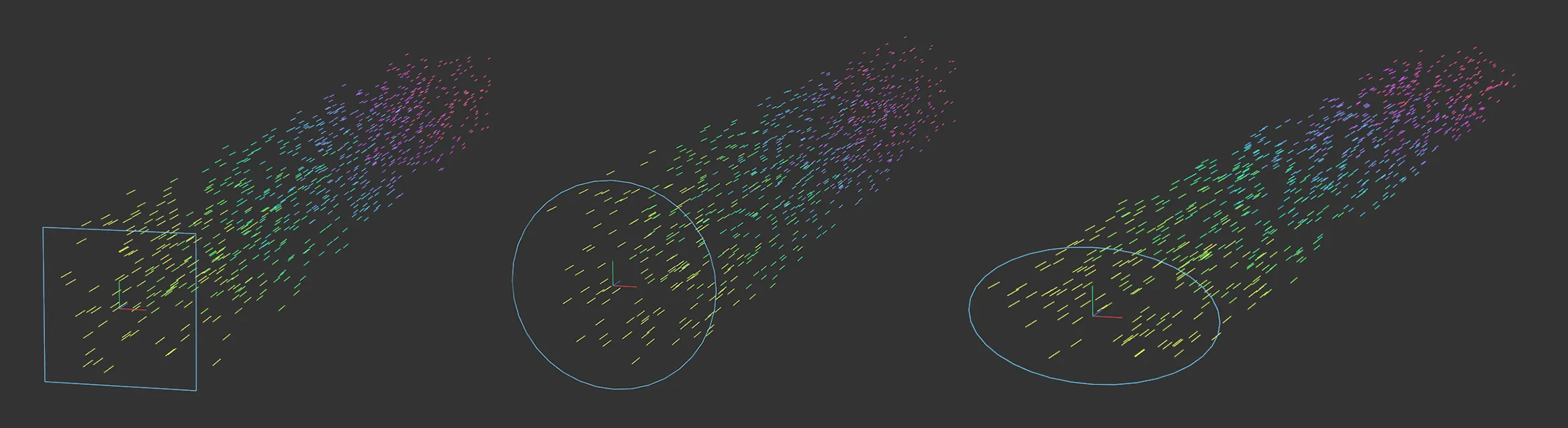
This image shows the 2D Emitter Shape settings of Rectangle, Circle and Ellipse.
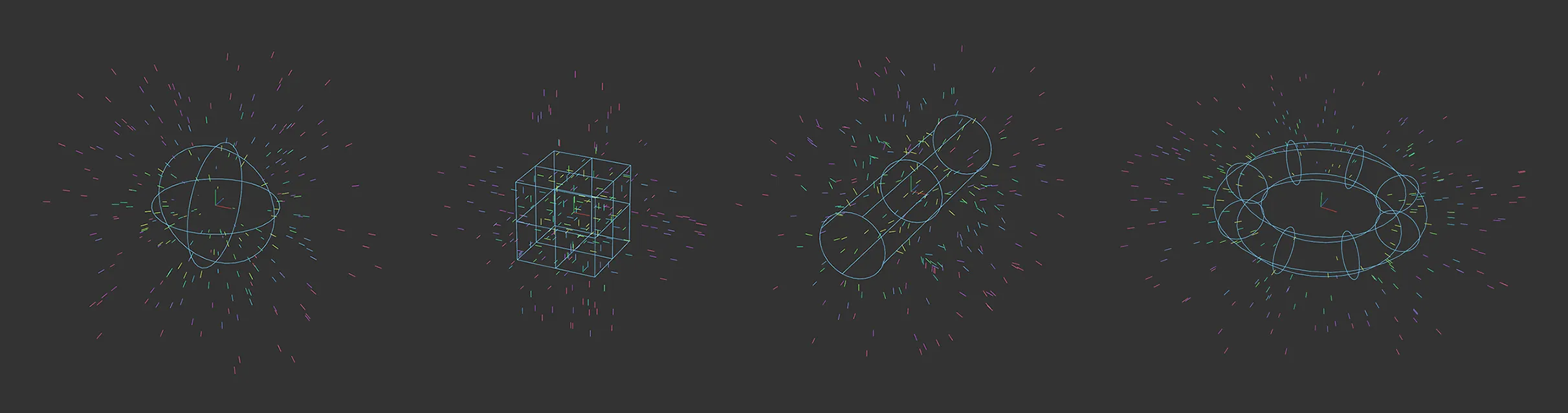
Here, you can see the 3D Emitter Shape settings of Sphere, Box, Cylinder and Torus.
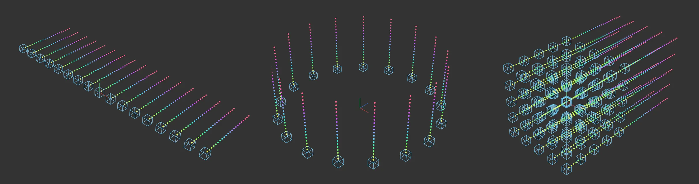
Image showing the Emitter Shape setting of Defined Emission in three different Mode settings: Inline, Circular and 3D Grid.
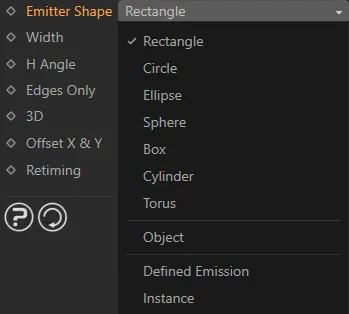
Emitter Shape menu options, with the default, Rectangle, selected.
Rectangle setting
Section titled “Rectangle setting”Emitter Plane
Section titled “Emitter Plane”By default, the particles are emitted on the Z+ plane.
This can be changed to: X+, X-, Y+, Y- , or Z-.
Width/Height
Section titled “Width/Height”From the Rectangle setting, the width and height can be increased or decreased using these settings.
This can also be done manually using the yellow handles in the viewport.
For different shapes, there are different options.
H Angle/V Angle
Section titled “H Angle/V Angle”By default, particles are released driven by the Emitter Plane setting, but the angle can be altered here, either horizontally or vertically, to broaden the dispersal.
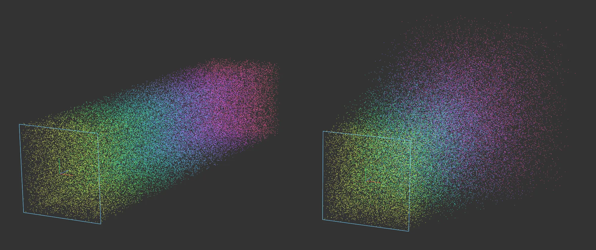
Default setting on the left. On the right, both the H Angle and V Angle are set to 10 degrees.
Edges Only
Section titled “Edges Only”Activating this will mean that particles are only emitted from the edges of the emitter.
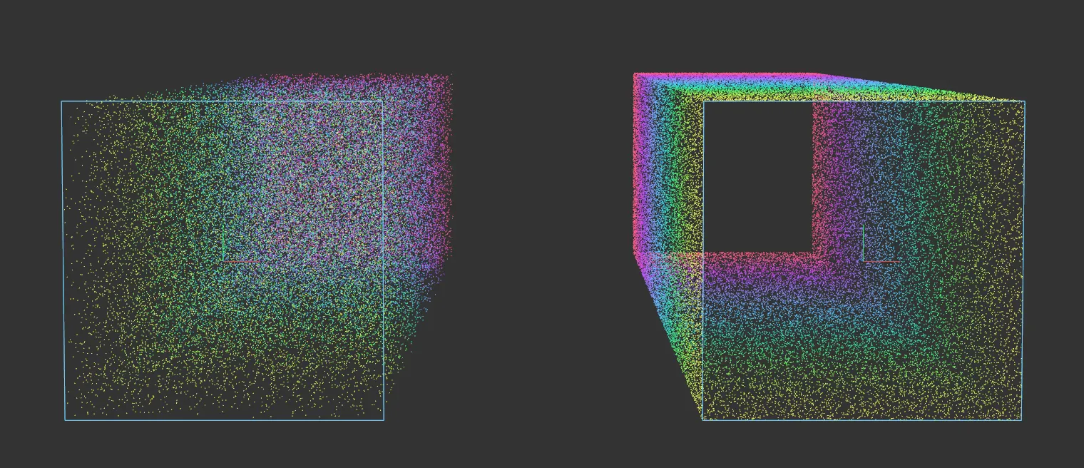
In this image, the right-hand emitter is emitting from the Edges Only setting.
Enabling this setting will change the emitter into a 3D shape.
From a Rectangle setting, this will become a cube.
Emitter Length
Section titled “Emitter Length”This setting only becomes available once 3D is enabled and allows the length of the emitter to be increased or decreased.
Offset X & Y
Section titled “Offset X & Y”Enabled, by default.
With the Emitter Plane setting at Z+, disabling this will result in the particles being emitted in a single beam, along the Z-axis, in the Z+ direction.
Changing the Emitter Plane setting will change the direction of this beam.
Offset Origin
Section titled “Offset Origin”Moves the origin of the particle emitter.
Retiming
Section titled “Retiming”Set at 100%, by default.
Increase or decrease to change the speed of the emitter.
At 0 (zero) there will be zero emissions.
Circle setting
Section titled “Circle setting”Emitter Plane
Section titled “Emitter Plane”By default, the particles are emitted on the Z+ plane.
This can be changed to: X+, X-, Y+, Y- , or Z-.
Disc Radius
Section titled “Disc Radius”Can be increased or decreased from here, with a value, or by dragging the yellow handle.
Cone Angle
Section titled “Cone Angle”By default, particles are released driven by the Emitter Plane setting, but the angle can be altered here to direct the particles into a cone shape.
Ring Only
Section titled “Ring Only”Activating this, emits the particles from the edge of the ring only.
Variation
Section titled “Variation”Applies a variation to where on the ring the particles are released.
Enabling this setting will change the emitter into a 3D shape.
From a Circle setting, this will become a cylinder.
Emitter Length
Section titled “Emitter Length”This setting only becomes available once 3D is enabled and allows the length of the emitter to be increased or decreased.
Offset X & Y
Section titled “Offset X & Y”Enabled, by default.
With the Emitter Plane set at Z+, disabling this will result in the particles being emitted in a single beam, along the Z-axis, in the Z+ direction.
Changing the Emitter Plane setting will change the direction of this beam.
Offset Origin
Section titled “Offset Origin”Moves the origin of the particle emitter.
Retiming
Section titled “Retiming”Increase or decrease to change the speed of the emitter.
At 0 (zero) there will be zero emissions.
Ellipse setting
Section titled “Ellipse setting”All settings are identical to Circle setting, except for the Radius, where there are two options: H-Radius and V-Radius.
H-Radius
Section titled “H-Radius”The horizontal radius of the Ellipse can be increased or decreased from here, with a value or by dragging the yellow handle.
V-Radius
Section titled “V-Radius”The vertical radius of the Ellipse can be increased or decreased from here, with a value or by dragging the yellow handle.
Sphere setting
Section titled “Sphere setting”As this is a 3D shape, the particles are not emitted in a plane direction, but in the 3D direction of normal, by default.
This is driven by the Direction setting.
Offset Origin
Section titled “Offset Origin”Moves the origin of the particle emitter.
At negative values, the particles will be emitted from inside the Sphere only.
At higher values, the particles will only be emitted from outside of the Sphere.
Radius
Section titled “Radius”Changes the radius of the Sphere.
Surface Only
Section titled “Surface Only”Particles are emitted from the surface, as opposed to the interior.
Direction
Section titled “Direction”Set at Normal, by default, the particles are emitted outwards in a 3D direction.
The other settings are: Random, X+ Axis, X- Axis, Y+ Axis, Y- Axis, Z+ Axis and Z- Axis.
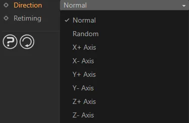
The Direction menu.
Random setting
Section titled “Random setting”The particles are emitted in a random direction.
X+, X-, Y+, Y-, Z+, Z- settings
Section titled “X+, X-, Y+, Y-, Z+, Z- settings”Emits the particles along that particular plane, as with the 2D Emitter Shape settings.
Retiming
Section titled “Retiming”Increase or decrease to change the speed of the emitter.
At 0 (zero) there will be zero emissions.
Box setting
Section titled “Box setting”Offset Origin
Section titled “Offset Origin”Moves the origin of the particle emitter.
At negative values, the particles will only be emitted from inside the Box.
At higher values, the particles will only be emitted from outside of the Box.
Increases or decreases the size of the Box in the X, Y and Z dimensions.
Faces Only
Section titled “Faces Only”Checking this box will cause the particles to emit from the surfaces of the Box only.
Emit Mode
Section titled “Emit Mode”Set at Random, by default, the particles are emitted in random directions.
This can be changed to Grid, where the emitting position is calculated from a grid, whose size is set in the Grid Size options and particles are emitted in straight lines, along the planes.
Grid Size
Section titled “Grid Size”Activated in Grid setting.
This increases or decreases the size of the grid.
At 50cm, with the Size settings at the default of 100cm in X, Y and Z, the particles will only be emitted from the points of the grid, as it is a 2 x 2 grid.
Direction
Section titled “Direction”Set as Faces, by default.
The particles are emitted from the faces of the Box.
The other options are along the planes, as with the 2D Emitter Shape settings.
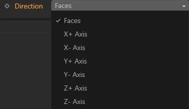
The Direction menu.
Retiming
Section titled “Retiming”Increase or decrease to change the speed of the emitter.
At 0 (zero) there will be zero emissions.
Cylinder setting
Section titled “Cylinder setting”Offset Origin
Section titled “Offset Origin”Moves the origin of the particle emitter.
At negative values, the particles will only be emitted from inside the Cylinder.
At higher values, the particles will only be emitted from outside of the Cylinder.
Radius
Section titled “Radius”Increases or decreases the radius of the Cylinder.
Height
Section titled “Height”Increases or decreases the height of the Cylinder.
This can also be done manually, using the yellow handle.
Direction
Section titled “Direction”Set at Radial, by default.
There are two other options: Standard and Bi-Directional.
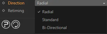
The Direction menu.
Radial setting
Section titled “Radial setting”The particles are emitted outwards from the Cylinder.
Standard setting
Section titled “Standard setting”The particles are emitted in a Z+ direction, from points along the Z-axis of the Cylinder.
Bi-Directional setting
Section titled “Bi-Directional setting”The particles are emitted in both Z+ and Z- directions from points along the Z-axis of the Cylinder.
Ring Only
Section titled “Ring Only”If enabled, the particles are only emitted from the surface of the Cylinder.
Retiming
Section titled “Retiming”Increase or decrease to change the speed of the emitter.
At 0 (zero) there will be zero emissions.
Torus setting
Section titled “Torus setting”Emitter Plane
Section titled “Emitter Plane”By default the setting is X+, which refers to the direction of the Torus, rather than any emission of the particles, which is controlled by the Direction setting.
The other settings are: X-, Y+, Y-. Z+ and Z-.
Offset Origin
Section titled “Offset Origin”Moves the origin of the particle emitter.
At negative values, the particles will only be emitted from inside the Torus.
At higher values, the particles will only be emitted from outside of the Torus.
Inner Radius
Section titled “Inner Radius”Increases or decreases the inner radius of the Torus.
Outer Radius
Section titled “Outer Radius”Increases or decreases the outer radius of the Torus.
Direction
Section titled “Direction”Set at Away From Center, by default.
The other options are: To Center, Random, X+ Axis, X- Axis, Y+ Axis, Y- Axis, Z+ Axis and Z- Axis.
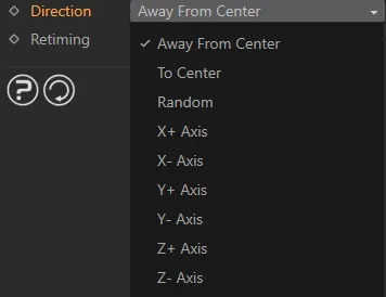
The Direction menu.
Away From Centre setting
Section titled “Away From Centre setting”The particle direction is from the Torus surface outwards, along a straight vector.
To Centre setting
Section titled “To Centre setting”The particles are moving from the Torus surface, in a direction towards the center.
Random setting
Section titled “Random setting”All particles are moving in random directions from the Torus surface.
X+ Axis, X- Axis, Y+ Axis, Y- Axis, Z+ Axis, Z- Axis
Section titled “X+ Axis, X- Axis, Y+ Axis, Y- Axis, Z+ Axis, Z- Axis”The particles are being emitted from the Torus surface in the direction determined by the axis setting, whether positive or negative.
Retiming
Section titled “Retiming”Increase or decrease to change the speed of the emitter.
At 0 (zero) there will be zero emissions.
Object setting
Section titled “Object setting”Once you select this setting, the menu changes to give many different options.
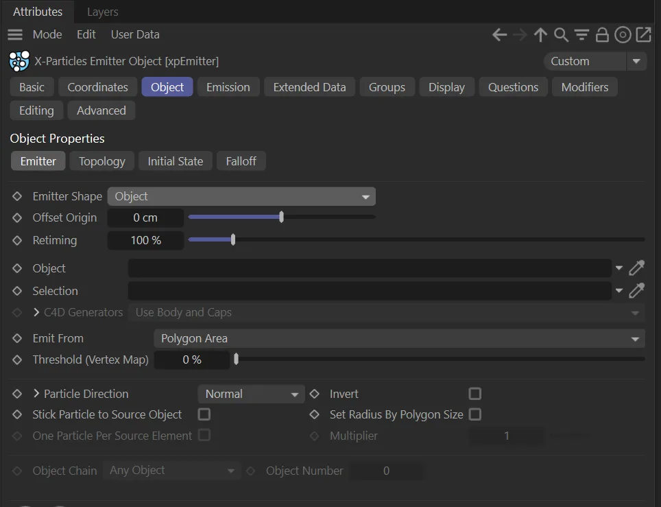
The Attributes Manager in Object setting for Emitter Shape.
Simply drag and drop your Object into the Object link field to begin using these settings.
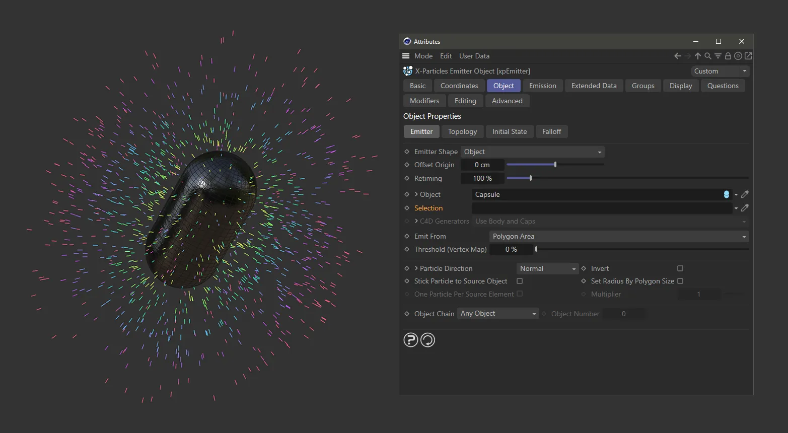
Here, a Capsule has been dragged and dropped into the Object link field and has begun emitting particles.
Offset Origin
Section titled “Offset Origin”Moves the origin of the particle emitter.
At negative values, the particles will only be emitted from inside the Object.
At higher values, the particles will only be emitted from outside of the Object.
Retiming
Section titled “Retiming”Increase or decrease to change the speed of the emitter.
At 0 (zero) there will be zero emissions.
Object
Section titled “Object”As mentioned, drag and drop your Object into this link field.
Particles will now be generated from the surface of that Object.
Selection
Section titled “Selection”A selection tag or vertex map can be dragged and dropped into this window.
You can use selection tags and vertex maps to control where particles will be born.
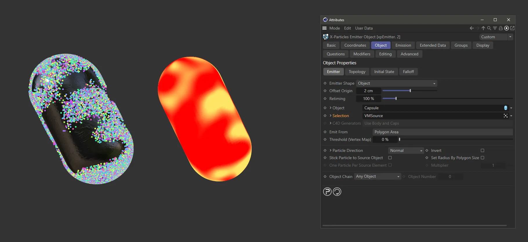
With the Emitter Shape set as Object, here, a Capsule has been dropped into the Object field and a vertex map has been placed in the Selection field. Particles are, as a result, being born only in the brighter areas of the vertex map.
C4D Generators
Section titled “C4D Generators”This drop-down menu determines what part of a Cinema 4D generator object the particles will be emitted from.
It is only available if the source object is a Cinema 4D generator object, otherwise it will be grayed out.
It has three options: Use Body and Caps, Use Body Only and Use Caps Only.
Use Body and Caps setting
Section titled “Use Body and Caps setting”Particles are emitted from both the body of the Object and its caps.
Use Body Only setting
Section titled “Use Body Only setting”Particles are only emitted from the body of the Object.
Use Caps Only setting
Section titled “Use Caps Only setting”Particles are only emitted from the caps of the Object.
Clicking the drop-down arrow next to the C4D Generators option will reveal further options to refine the particle emission from the generators object caps.
These options are only available if filleted caps are turned on in the Cinema 4D generator object.
C1 and C2 are the polygons/points making up the main part of the cap, while R1 and R2 are the polygons which form the rounded part of the cap.
Click any of these boxes to emit from that part of the cap.
Emit From
Section titled “Emit From”This option determines the source of the emitted particles.
The default setting is Polygon Center.
Other options are: Polygons, Polygon Area, Points, Edges, N-gon Center, Texture, Object Color, Illumination, Object Position, Object Volume and Voxel Grid.
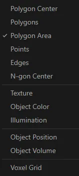
The Emit From menu.
Polygon Center setting
Section titled “Polygon Center setting”The particles are emitted from the center of the polygons of the Object .
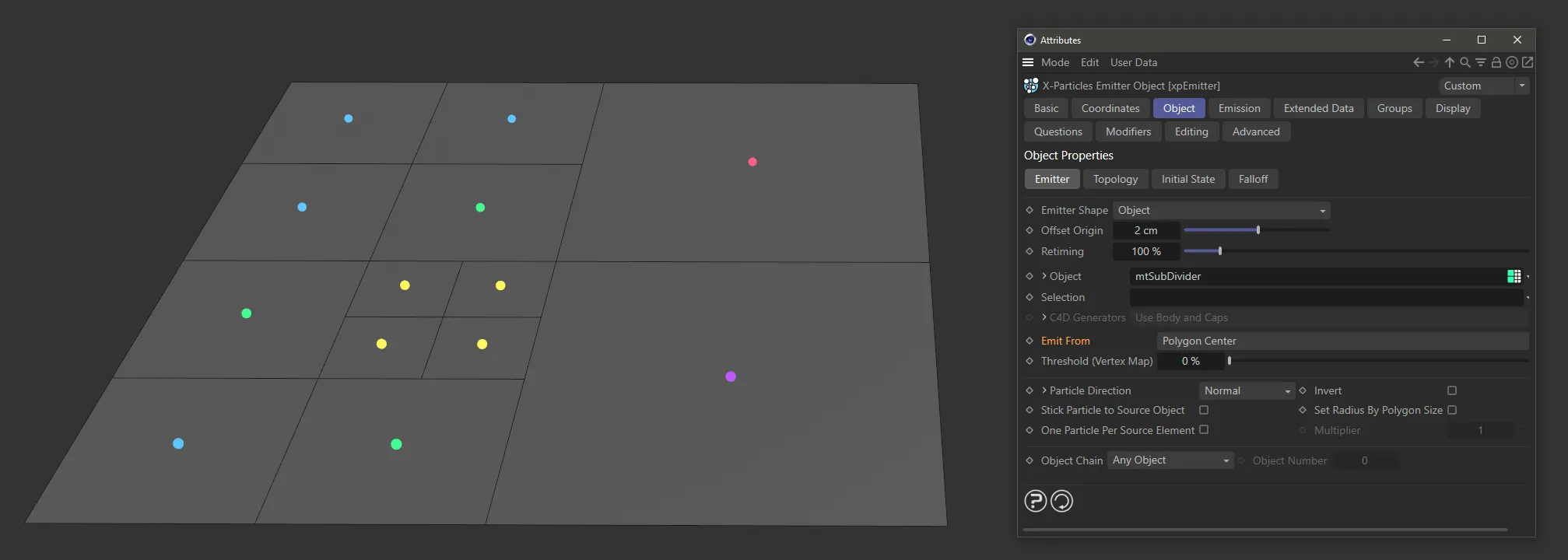
With Emit From set as Polygon Center, the particles are being emitted from the center of each individual polygon.
Polygons setting
Section titled “Polygons setting”Particles are emitted from a random position on the polygon faces.
This is not weighted by size; all polygons emit the same amount of particles.
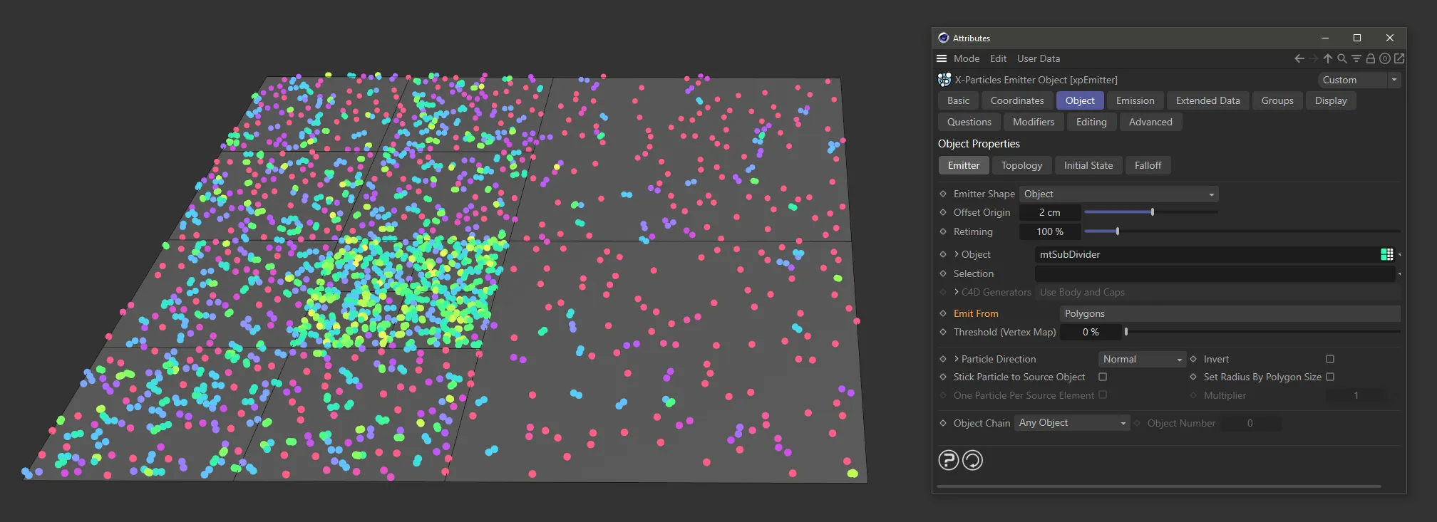
With Emit From set as Polygons, particles are being emitted from random positions on the polygon faces, but with a uniform amount of particles generated per polygon, resulting in more densely populated smaller polygons.
Polygon Area setting
Section titled “Polygon Area setting”Particles are emitted from a random position on the polygon faces.
This is the same as Polygons setting, except that in this case emission is weighted by the size of the polygon, with larger ones emitting more than smaller.
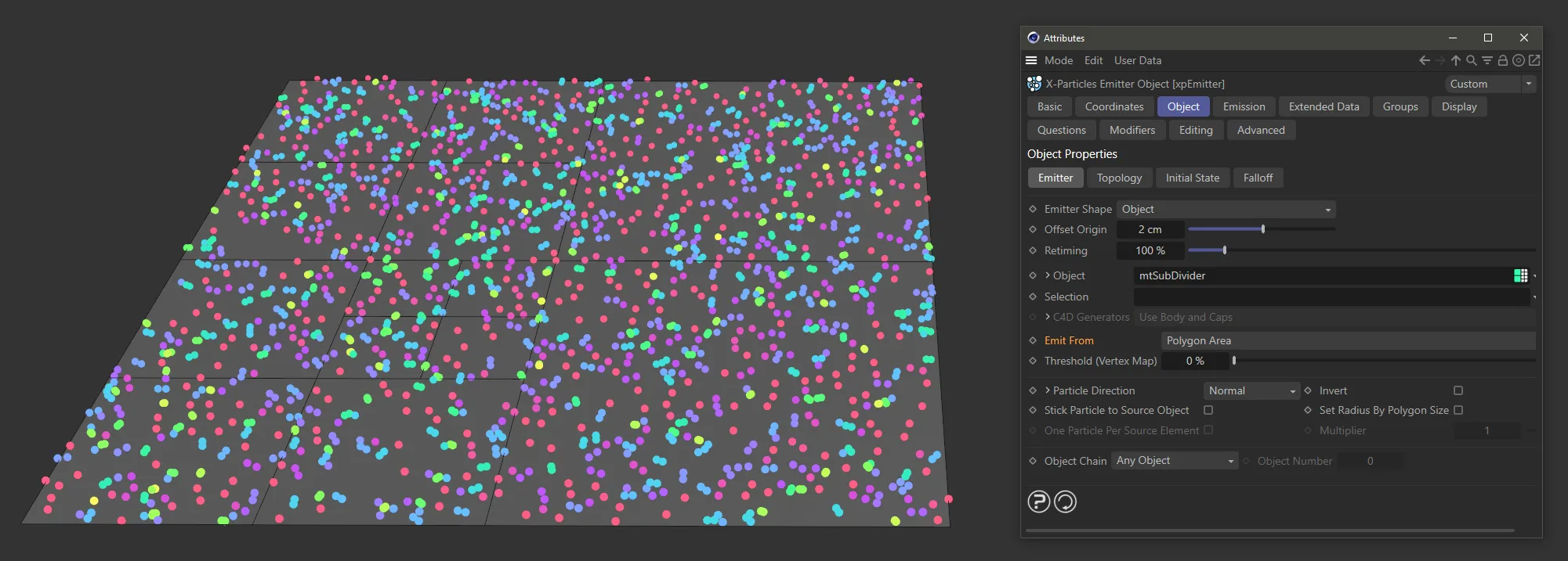
Here, Emit From is set as Polygon Area, with particles being emitted based on the area within all available polygons.
Points setting
Section titled “Points setting”Particles are emitted from the points of the Object (vertices).
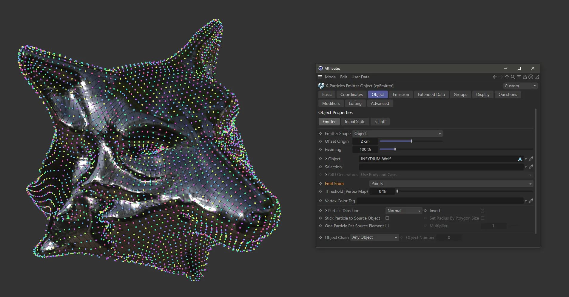
Emit From is set as Points, with the result that particles are emitted from the polygon vertices.
Edges setting
Section titled “Edges setting”Particles are emitted from the edges of the Object, or from along the length of a spline.
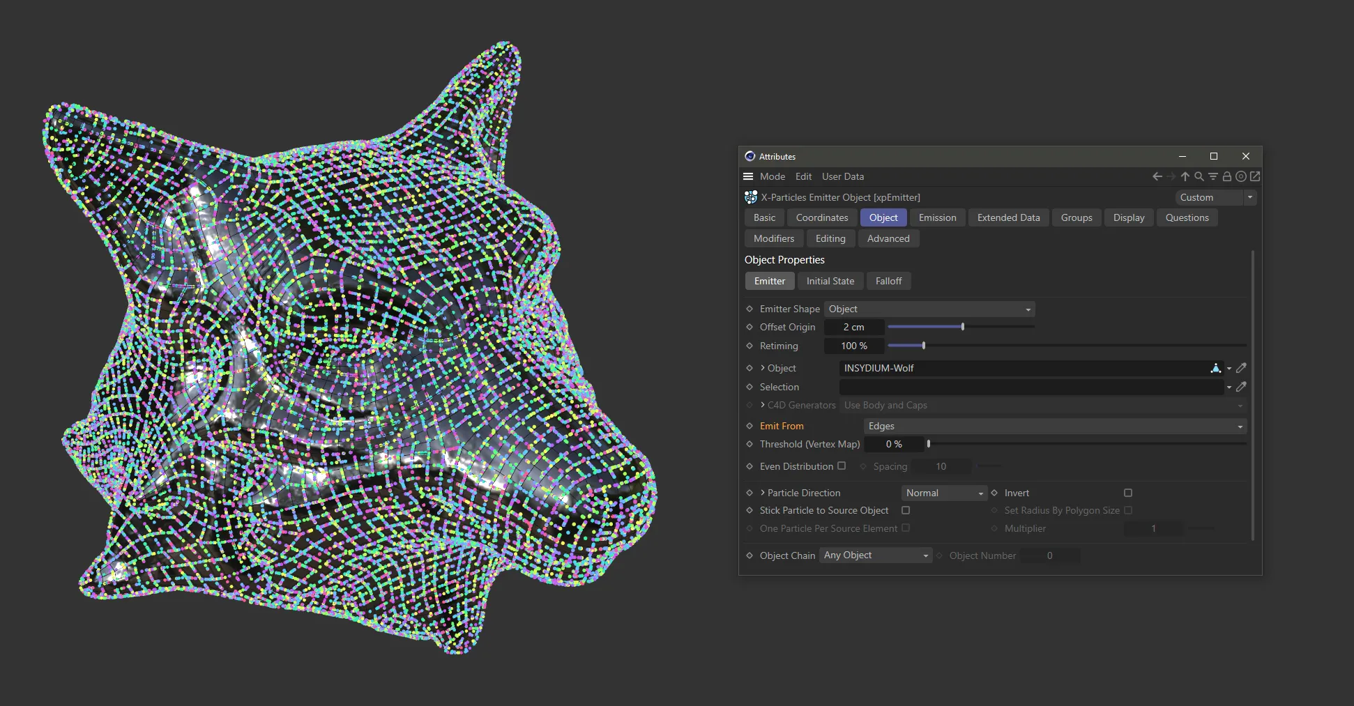
In this image, Emit From is set as Edges. Particles are being emitted along the length of the polygon edges (with the Even Distribution parameter disabled).
N-gon Center setting
Section titled “N-gon Center setting”Particles are emitted from the center of any N-gons in the Object
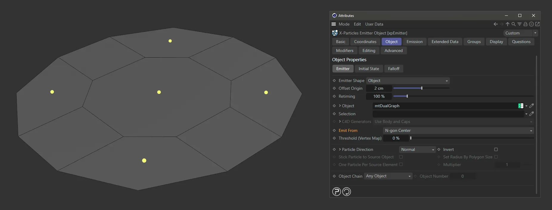
Particles are being emitted from the center of N-gons, with Emit From set as N-gon Center.
Texture setting
Section titled “Texture setting”Emission from the Object is controlled by a Texture, with additional settings for the Texture.
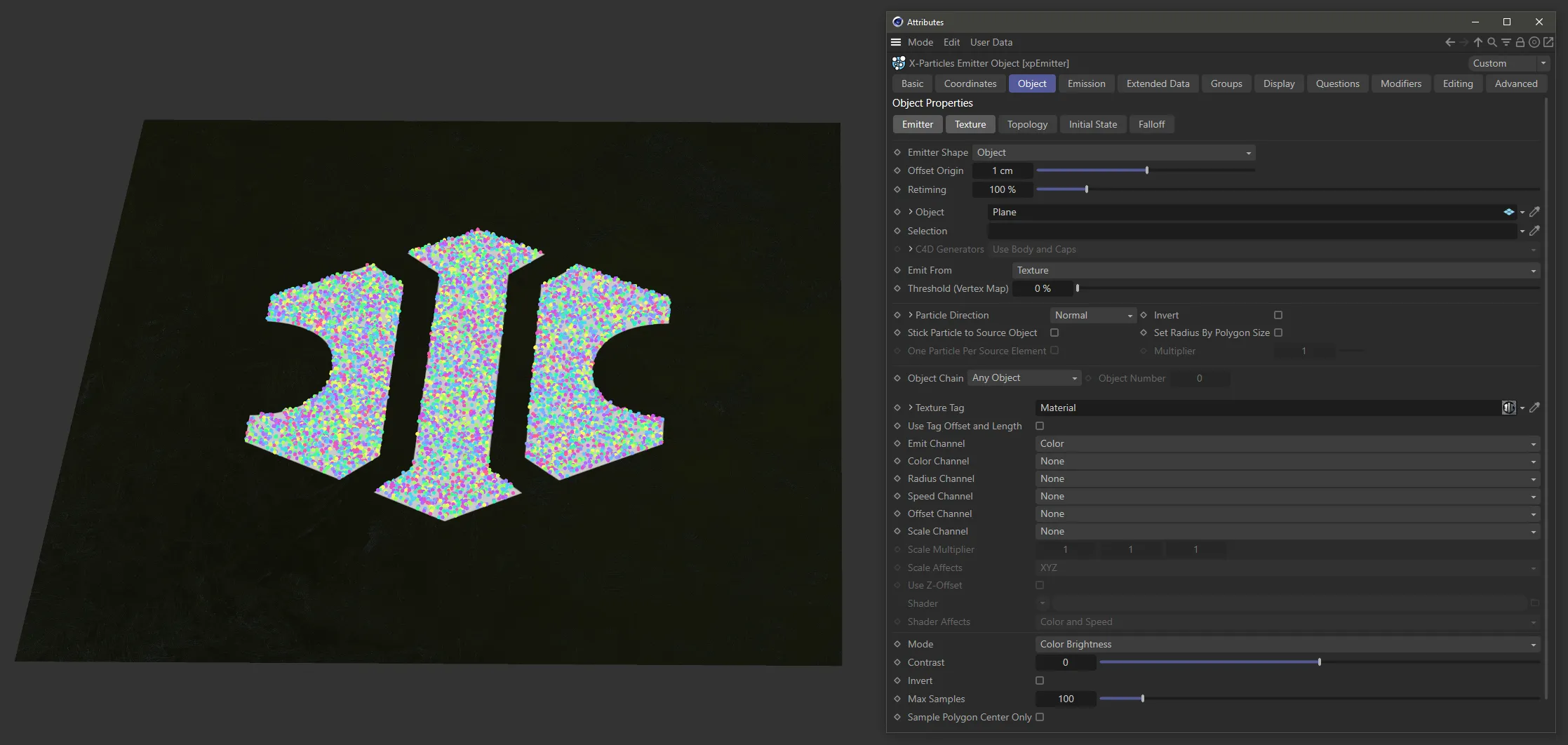
Here, with Emit From set as Texture, the Texture material is driving emission of particles.
Object Color setting
Section titled “Object Color setting”Emission is controlled by the color of the Object.
Particles are able to generate on brighter colors, with darker colors restricting their ability to be generated.
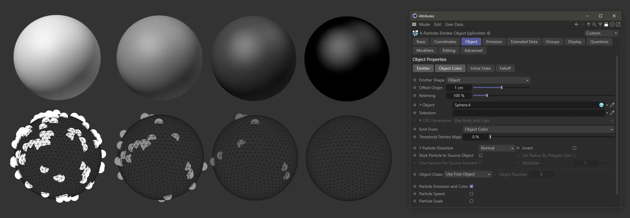
Emit From is set as Object Color here. The Emitter Shape is set to Object mode and linked to each of these Spheres. The Spheres are colored from white on the left to black on the right. The resulting emission (below) is driven by the Sphere colors, from full emission on the white Sphere to no emission on the black Sphere.
Illumination setting
Section titled “Illumination setting”Emission from the Object is determined by the illumination of the surface by specific scene lights.
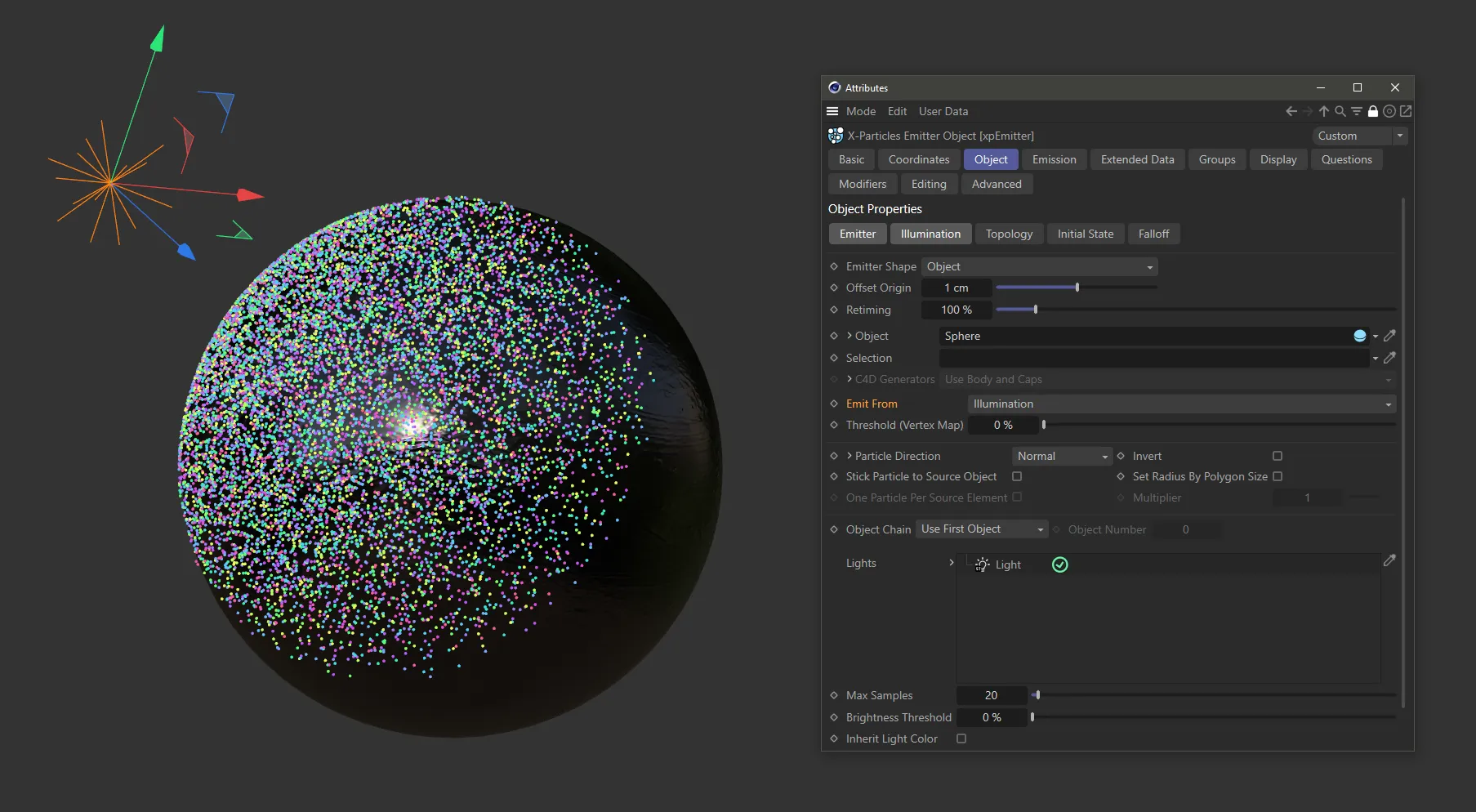
In this image, the Emit From setting is Illumination, with particle emission driven by illumination onto the object surface.
Object Position setting
Section titled “Object Position setting”Particles are emitted from the world position of the Object.
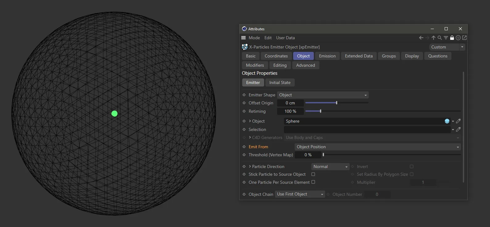
Emit From setting as Object Position. In this case particles are only emitted from the world position of the Object.
Object Volume setting
Section titled “Object Volume setting”Particles are emitted from a random point inside the Object.
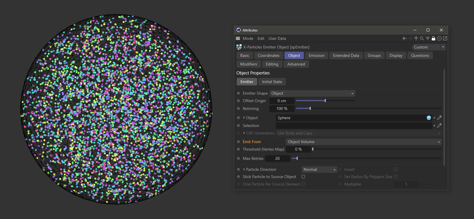
Here, Emit From is set as Object Volume, driving random emissions from within the Object (in this case, a Sphere).
Voxel Grid setting
Section titled “Voxel Grid setting”The Object is divided up into a grid of square cells and particles are emitted from the center of the cells.
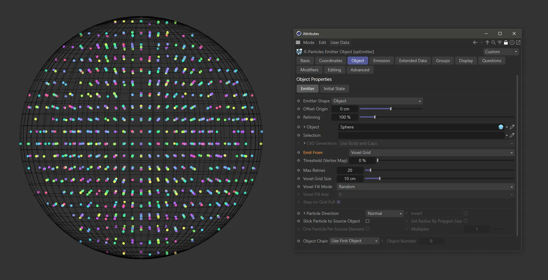
Emit From set as Voxel Grid, with particles being generated from the center of the cells.
Threshold (Vertex Map)
Section titled “Threshold (Vertex Map)”If you add a vertex map to the Selection field, you can set a threshold for its strength.
By default this is set to 0 (zero) %, so particles will be emitted wherever the strength is greater than zero.
If you set the value to 20%, particles will only be emitted from the vertex map where the strength is higher than 20%.
Vertex Color Tag
Section titled “Vertex Color Tag”If you set Emit From to the Points setting then this option becomes available, allowing you to paint the vertices of the Object with color.
The particles will then take their color from the vertex from where they are emitted.
If the Object already has a Vertex Color Tag, then the color will automatically be taken from it.
With multiple tags, you can choose which one to use by dragging and dropping it into this link field.
Even Distribution / Spacing
Section titled “Even Distribution / Spacing”If you set Emit From to the Edges setting, then these two further options become available.
By default the emission point is chosen from a random point on the edge, which can lead to irregular distribution of particles.
Enabling this setting will give an even distribution of emission points, according to the Spacing setting.
Spacing
Section titled “Spacing”The Spacing setting indicates how many emission points there will be along the edge.
The value is used together with the edge length to determine this number, ensuring that the spacing of the emission points is constant.
The higher the number, the greater the space between the emitted particles.
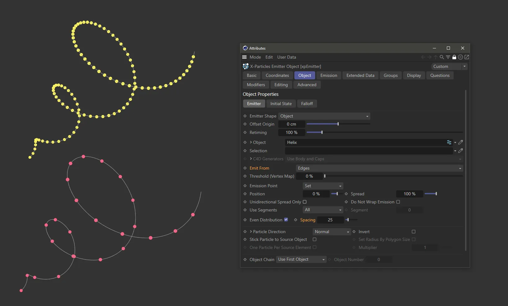
Edges setting with a Helix spline used as the Object in Emitter Shape. The Spacing parameter is set to 100 on the upper spline and reduced to 25 below.
With the Edges setting in Emit From, there are further options available if the Emitter Shape Object is a spline.
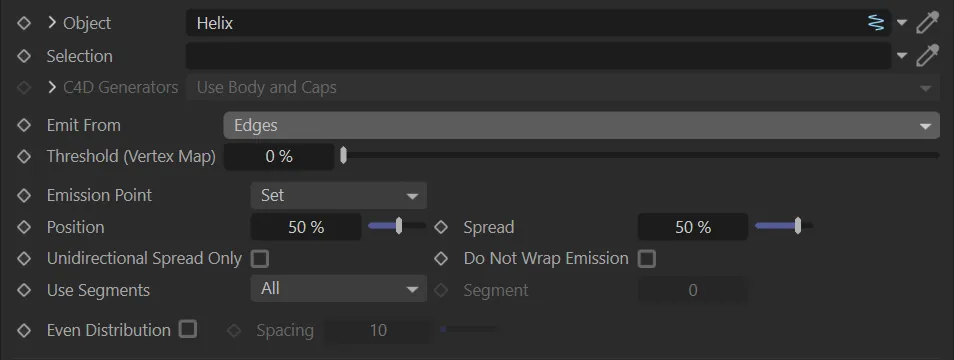
Additional options for spline settings in Edges mode.
Emission Point
Section titled “Emission Point”Set at Random, by default, emitting particles from random positions along the spline.
The other option is Set, which gives you the ability to set the position along the spline to emit from, by opening up two further options, which work in conjunction with each other.
Position
Section titled “Position”If Emission Point is Set, then this value represents a percentage position along the spline’s length from where the particles will be emitted.
Animation to demonstrate the use of the Position value parameter with Emission Point as Set.
Spread
Section titled “Spread”If Emission Point is Set, this option will spread the particles around the emission point.
With the Spread set at 0 (zero) %, the particles will be emitted from the single point determined by the Position setting*.*
If the Position is set at 50%, with the Spread set at 50%, the particles will be emitted from +/-25% from the Position setting.
This means they will be emitted from points between 25% and 75% of the length of the spline.
Unidirectional Spread Only
Section titled “Unidirectional Spread Only”The spread will only be in one direction from the Position setting on the spline.
If the Position is set at 50%, with the Spread set at 50% (as above), with Unidirectional Spread Only checked, then the emission will be from 50% to the end of the spline.
Do Not Wrap Emission
Section titled “Do Not Wrap Emission”When keyframing, with Unidirectional Spread Only enabled, the particles could continue to be emitted after 90 frames, by starting at frame 1.
If you don’t want this, check this box to prevent the wrap round effect from occurring.
Use Segments
Section titled “Use Segments”There are two options.
The default, All and Select.
All mode
Section titled “All mode”In a multi-segment spline, a particle will be emitted from a randomly chosen segment.
Select mode
Section titled “Select mode”In a multi-segment spline, all particles will be emitted from the segment given in the Segment setting.
Segment
Section titled “Segment”This option is grayed out unless Select mode is enabled.
The value here then represents the segment of the spline that you choose.
Even Distribution
Section titled “Even Distribution”This option is only available if Emission Point is Set.
When enabled, particles are evenly spaced along the spline, ignoring any Position setting.
The Spread setting can still be used to produce small clumps of particles at regular intervals.
Spacing
Section titled “Spacing”The Spacing setting indicates how many emission points there will be along the spline.
The value is used together with the spline length to determine this number, ensuring that the spacing of the emission points is constant.
The higher the number, the smaller the space between the emitted particles.
Max Retries
Section titled “Max Retries”If you choose to Emit From either Object Volume or Voxel Grid, this option will be available.
In both cases, the emitter must determine if the chosen emission point is within the Object.
If it is not, then another point is selected.
With some objects it may take several attempts to find a suitable emission point and could slow down the animation.
This option gives you the ability to place a suitable limit on the maximum number of attempts.
Particle Direction
Section titled “Particle Direction”This determines the initial direction of each emitted particle.
The default is Normal, but the other options are: Phong Normal, Random, X+ Axis, X- Axis, Y+ Axis, Y- Axis, Z+ Axis and Z- Axis.
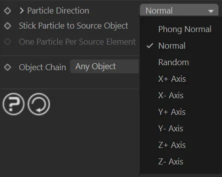
Particle Direction menu.
Phong Normal
Section titled “Phong Normal”Particles are emitted along the phong normal of the selected point on the surface.
Normal
Section titled “Normal”Particles are emitted along the face normal for polygon objects.
If the Object is a spline, then particles will be emitted radially away from the spline.
Random
Section titled “Random”Particles are emitted in random directions.
X+ Axis/ X- Axis/ Y+ Axis/ Y- Axis/ Z+ Axis/ Z- Axis
Section titled “X+ Axis/ X- Axis/ Y+ Axis/ Y- Axis/ Z+ Axis/ Z- Axis”Particles are emitted along the axis of the Object on that plane (not the world axis) in a positive, or negative, direction.
Invert
Section titled “Invert”If enabled, this will invert the selected direction.
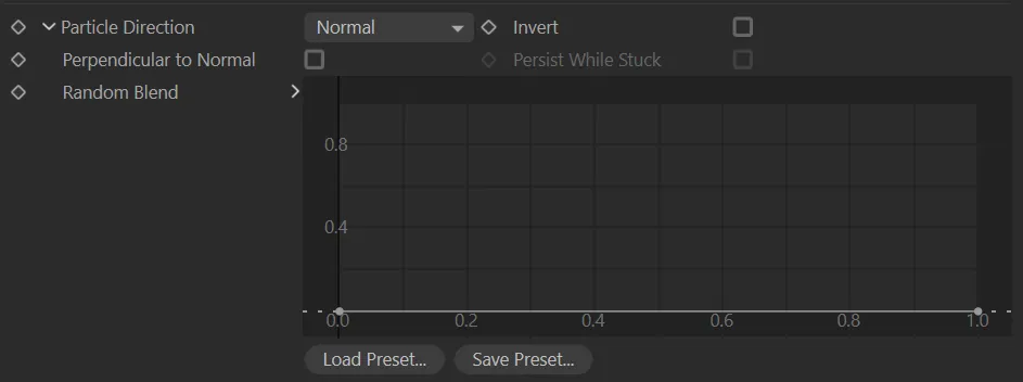
Additional parameter options from Particle Direction.
Clicking the drop-down arrow next to the Particle Direction parameter will give the additional options in the image above.
Perpendicular to Normal
Section titled “Perpendicular to Normal”If this option is enabled, along with Particle Direction set to Normal, then particles will be emitted at a randomly-selected direction perpendicular to the surface normal.
Persist While Stuck
Section titled “Persist While Stuck”This option will only become available when Particle Direction is set to Normal and Stick Particle to Source Object is enabled.
It will allow the particle direction to be continually updated as the surface normal changes.
Random Blend
Section titled “Random Blend”You can manipulate this spline curve to blend the calculated particle direction with a random element.
Stick Particle to Source Object
Section titled “Stick Particle to Source Object”When enabled, any particles generated will stick to the Object which acted as the emission source.
Set Radius By Polygon Size
Section titled “Set Radius By Polygon Size”Only available with certain Particle Direction settings.
If enabled, the particle radius is determined by the size of the polygon from which it is emitted.
The minimum radius used will be the Radius setting (in the Emission tab) minus the Variation value.
The maximum radius used will be the Radius setting plus the Variation value.
One Particle Per Source Element
Section titled “One Particle Per Source Element”Once enabled, this will bypass the Birthrate parameter (in the Emission tab), instead forcing the emitter to emit one particle only for each element (polygon or point) in the Object.
This option is only available when Emit From is set to Polygon Centre, Points or Object Position.
Multiplier
Section titled “Multiplier”This option is only available when Emit From is set to Object Position and One Particle Per Source Element is enabled.
It allows you to multiply the number of emitted particles by the value you input.
Object Chain
Section titled “Object Chain”Set as Any Object, by default.
If you drag a generator-type object, such as a Cloner or Array object into the Object link field, the emitter converts the Object to a polygon object internally before calculating where to create the particle.
However, generators can create a chain of objects when converted.
The additional choices help with this: Use First Object, Use Last Object, Use Specific Object, Any Object, Connect Objects.
Use First Object
Section titled “Use First Object”The first object in the chain is used.
Use Last Object
Section titled “Use Last Object”The last object in the chain is used.
Use Specific Object
Section titled “Use Specific Object”The object given in the Object Number parameter is used.
Any Object
Section titled “Any Object”An object is selected randomly from the chain.
Connect Objects
Section titled “Connect Objects”The child objects are joined into one large object and that is then used as the emission source.
Object Number
Section titled “Object Number”The number of the object in an object chain to use if Object Chain is set to Use Specific Object.
The number is zero-based, i.e. the first object has number 0 (zero).
Voxel Grid setting
Section titled “Voxel Grid setting”When you select this emission type, you see the additional four settings.
Voxel Grid Size
Section titled “Voxel Grid Size”This is the size of the grid in scene units.
It determines how many voxels are used and therefore the number of generated particles.
Voxel Fill Mode
Section titled “Voxel Fill Mode”Set at Random, by default, voxels are selected randomly and a particle emitted from that voxel.
The alternatives setting is Ordered, where the voxels are used in order.
You can select the order in which to use the voxel grid with Voxel Fill Axis setting.
Voxel Fill Axis
Section titled “Voxel Fill Axis”If Ordered fill mode is selected, the grid can be filled along the X, Y, or Z axis using this drop-down menu.
If you set the particle speed to zero and check Stop on Grid Full, you will end up with the object filled with a grid of particles.
Stop on Grid Full
Section titled “Stop on Grid Full”Only available if Ordered fill mode is selected.
Emission of new particles will stop when a particle has been emitted from each voxel.
Defined Emission setting
Section titled “Defined Emission setting”Defined Emission enables you specify exactly where and how many particles will be emitted using a variety of adjustable patterns.
When you select this option, the interface changes significantly.
Defined Emission menu options.
Set as Inline, by default, this enables you to choose the pattern to use.
The additional options are: Circular, 3D Grid and Fragmenter List.
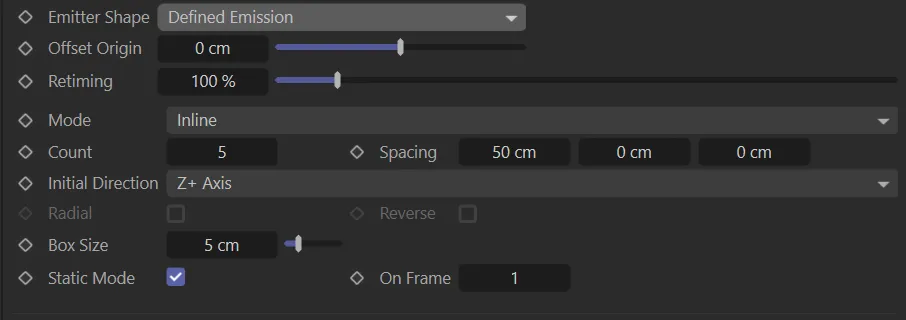
Inline mode
Section titled “Inline mode”This mode has two settings.
Sets the number of boxes in the line.
Spacing
Section titled “Spacing”The spacing between the boxes, on the X, Y, and Z axes.
Circular mode
Section titled “Circular mode”This mode has six settings.
Sets the number of boxes in the circle.
Radius
Section titled “Radius”The circle’s radius.
Repeat
Section titled “Repeat”The number of circles; these will be stacked on top of each other along the Y axis of the emitter.
Repeat Spacing
Section titled “Repeat Spacing”The distance between the circles, if there is more than one.
Slice Start, Slice End
Section titled “Slice Start, Slice End”By default the circle is the full 360 degrees, but you can use these settings to make a part-circle from (for example) 90 to 270 degrees, or any other combination.
3D grid mode
Section titled “3D grid mode”This mode has two settings.
Sets the number of boxes in the grid along each of the three axes.
Spacing
Section titled “Spacing”The spacing between the boxes, on the X, Y, and Z axes.
Fragmenter List mode
Section titled “Fragmenter List mode”This option causes the emitter to work in conjunction with an xpFragmenter object in Objects mode.
Initial Direction
Section titled “Initial Direction”This drop-down sets the initial direction of the particles.
This can be: Random.
Each particle has a randomly-assigned direction; or a designated axis setting, whereby the particles move along the positive or negative of that axis.
Radial
Section titled “Radial”Enabled, this is only available in Circular mode.
It causes the Initial Direction setting to be ignored and the particles emitted in a radial fashion.
Reverse
Section titled “Reverse”Only available in Circular mode and if the Radial option is enabled.
It causes the particles to be emitted inwards towards the centre of the circle.
Box Size
Section titled “Box Size”The size of the boxes in the editor.
These are never rendered.
Static Mode
Section titled “Static Mode”One of the most useful ways to use the Defined Emission setting is for the emitter to emit one particle for each box on just one frame.
By linking the emitter to a generator or sprite object, you then have a simple cloner, but with the advantage that the particles (and therefore the objects) can be controlled by the X-Particles particle engine.
Enabled, by default, this is set up automatically.
It will set the emission to occur on one frame, which you specify in the On Frame field.
On Frame
Section titled “On Frame”The frame to emit on if Static Mode is checked.
Instance setting
Section titled “Instance setting”If you select Instance from the Emitter Shape menu, the menu changes.

Instance setting menu option.
Using this shape forces the emitter to be an instance of another emitter.
In that case, settings such as speed, editor shape, color, etc. are all derived from the source emitter, not from the instance emitter.
If you make an instance emitter the child of a cloner or an array, all the clones will work as normal, as copies of the source emitter.
Emitter
Section titled “Emitter”Drag and drop the source emitter to use into this field.
If the field is empty, the emitter will not emit any particles.
Initial State tab
Section titled “Initial State tab”Use Initial State
Section titled “Use Initial State”Once the initial state has been set, you can turn it on or off.
Turning it off does not clear the initial state from memory.
This animation demonstrates how using the Set State button at a chosen point in your animation will allow you to set the initial state at which your scene will begin.
Accessed by clicking the drop-down arrow to the left of the words Use Initial State.
This is used to scale the particle system if you are importing from, or exporting to, the Partio file format (that is, if you click ‘Load State…’ or ‘Save State…’).
To save the initial state to a Partio format just set the file extension, e.g. .prt for PRT.
Compressed
Section titled “Compressed”If enabled, the initial state data will be compressed in memory.
Set State
Section titled “Set State”Click this button to set the initial state at the frame of your choice.
Clear State
Section titled “Clear State”Clicking this button will delete the initial state data.
Load State
Section titled “Load State”Click this button to load a saved initial state.
Save State
Section titled “Save State”Save the initial state to disk.
The saved file has the same format as a cache file.
Texture tab
Section titled “Texture tab”These settings are used when emission from an object is controlled by a texture.
This tab is only available when Texture is selected from the Emit From setting.
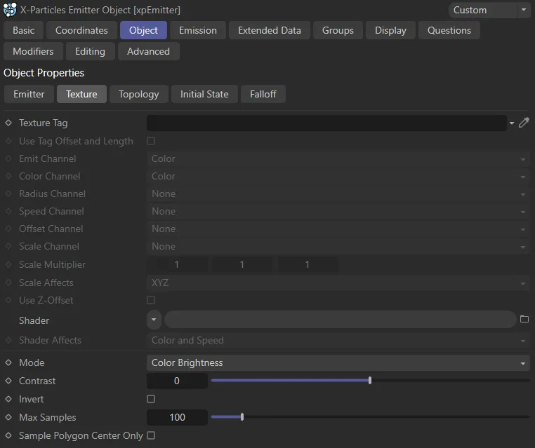
The Texture tab menu.
Texture Tag
Section titled “Texture Tag”You can drag a texture tag into this field and the emitter will use the material referenced by that tag.
Any of the texture tags assigned to the object may be used.
Any projection mapping can be used in the tag except Frontal or Camera mapping.
Using a tag is convenient if you have already set up a material and don’t want to have to duplicate it in another shader.
Once you add the tag to this field, you can select the channel to sample in the Channel drop-down menu, but you can no longer use the Shader field.
Use Tag Offset and Length
Section titled “Use Tag Offset and Length”Check this box to enable…
Emit Channel
Section titled “Emit Channel”This is the material channel which governs the emission of particles.
If you have dragged a texture tag into the Texture Tag field, you can choose the channel to use from the material.
By default this is the Color channel, but you can choose from several others.
One thing you can do is use a channel which is not being used in the material.
The emitter can still sample that channel even though it is not being used in the material.
If you set this channel to None then the texture will not control the emission of particles but you can still use the Color Channel and Speed Channel settings.
Color Channel
Section titled “Color Channel”This is the material channel which controls the particle color.
The particles will take their color from this channel, by default.
This does not have to be the same channel as the Emission channel.
Radius Channel
Section titled “Radius Channel”This is the material channel which controls the particle radius.
To see different particle radius values, you must set the radius variation parameter in the Emission tab to something other than 0 (zero).
The minimum radius used will be the radius setting minus the variation value; the maximum radius will be the radius setting plus the variation value.
Areas of zero brightness in the texture (i.e. black) will give the minimum radius while white areas will give the maximum radius.
Speed Channel
Section titled “Speed Channel”This is the material channel which controls the particle speed.
The particles will take their speed from this channel, which is turned off by default.
This does not have to be the same channel as the Emission or Color channels.
The actual speed will be between zero (for black surfaces) and the speed set in the emitter (for white surfaces).
Offset Channel
Section titled “Offset Channel”The selected channel controls the offset of a particle from the surface.
To use it, first set Offset Origin in the Emitter tab to a suitable maximum value.
Then any particle emitted from a black area of the surface will have zero offset, while any particle emitted from a white area will have the maximum offset.
Scale Channel
Section titled “Scale Channel”This is the material channel which controls the particle scale.
The particles will take their scale from this channel, which is turned off by default.
This does not have to be the same channel as the Emission, Color or Speed channels.
Each component of the sampled color affects one axis of the scale value.
That is, the red component affects the X-axis scale, the green component the Y-axis scale and the blue component the Z-axis scale.
When this channel is used, two more controls become available.
These are the Scale Multiplier and Scale Affects controls.
Scale Multiplier
Section titled “Scale Multiplier”The sampled color from a texture will always return values between 0 (zero) and 1.
Clearly, the particle scale cannot be restricted to such a narrow range.
The value in this setting is multiplied with the color value to give the actual scale.
This enables you to scale the particles up (or down) as much as desired.
You can affect each scale axis independently.
Scale Affects
Section titled “Scale Affects”By default, the scale color will affect all three axes in the scale.
If you want to restrict its effect to one or two axes instead this drop-down has all seven possible combinations, ranging from only one axis up to all 3, in any combination.
Use Z-Offset
Section titled “Use Z-Offset”If the particle scale is affected by the texture, then the particle will continue to be emitted at the same point.
This will cause larger particles to be ‘embedded’ more deeply in the polygon surface.
In some cases you might prefer the ‘base’ of the particles to be aligned to the same level.
To do that, enable this.
In most cases you will also need to turn on particle rotations and set them to Tangential, to align the Z-axis of the particle along the direction of travel.
You may also need to adjust the offset from the surface with the Offset Origin slider.
Shader
Section titled “Shader”Instead of using an existing texture tag, you can set up any shader in exactly the same way as if you were using the material editor.
Or, you can copy a channel from a material and paste it into this field.
If you set up a shader, then add a texture tag, only the tag is used; the shader will be ignored.
Shader Effects
Section titled “Shader Effects”Set as Color and Speed, by default, this drop-down governs which parameters of the particle are affected by the shader.
The alternative options are: Color, Speed and Neither.
Set as Color Brightness, by default, this is used when controlling particle emission with a texture.
It has no effect on particle color.
It has three other settings: Red, Green and Blue.
Color Brightness
Section titled “Color Brightness”The brighter the color, the more particles are emitted.
If you find that more particles are being emitted from darker areas than you would like, you can increase the Contrast setting to reduce emission from dark areas.
Conversely, turning down the contrast below 0 (zero) will increase emission from darker areas.
Red, Green and Blue
Section titled “Red, Green and Blue”These options will emit more particles where there is a higher proportion of red (or green, or blue) in the color.
Again, the contrast can be used to increase or decrease emission.
Invert
Section titled “Invert”Enabling this will invert the emission so that (for example) if Color Brightness is being used, this will emit more particles from darker areas than bright ones.
Contrast
Section titled “Contrast”This is used in conjunction with the Mode setting.
Max Samples
Section titled “Max Samples”The emitter samples the color of the object to find a point where a particle can be emitted.
Should the emitter struggle to find a point where a particle can be emitted, it would potentially search for one for ever, which would lock Cinema 4D up.
To prevent that, the emitter only tries the number of samples in this field and then gives up if it can’t find a suitable point.
Sample Polygon Center Only
Section titled “Sample Polygon Center Only”Normally, emission from a texture works by sampling all areas of a polygon.
If you only want to sample the centre of the polygon, enable this setting.
Topology tab
Section titled “Topology tab”With this tab you can control emission from an object by the height and/or slope of the polygon used for emission and you can opt to emit from an object’s curvature.
Height and slope controls are available in the polygon emission modes: polygon centre, polygon area, texture, and illumination; curvature is available in all those modes except polygon centre.
When you select one of these modes, the Topology tab becomes available.
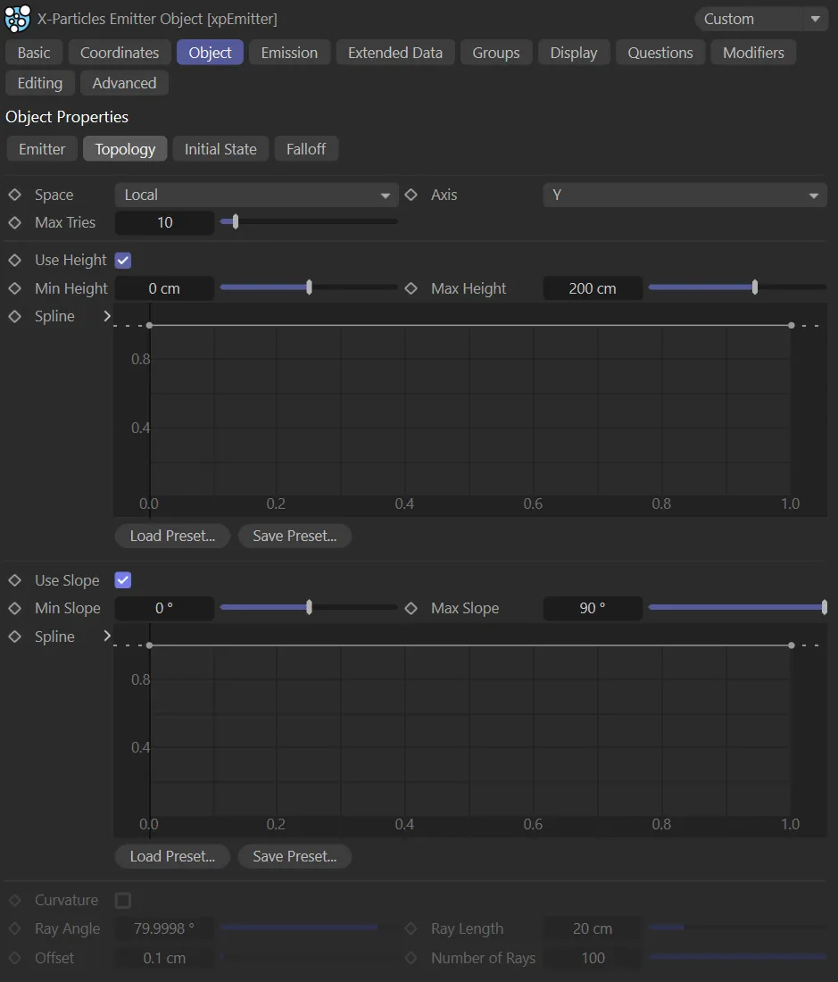
The Topology tab menu.
Set as Local, by default. The alternative is World.
The position of the particle emission point is relative to the emission object (to its axis).
This means that moving or rotating the object will not affect the height or slope of any polygon, since they remain the same relative to the axis.
With this option, the height and slope of any polygon is relative to the 3D world axis.
Moving or rotating the emission object may then have a significant effect on the polygons used for emission.
The height and slope are assessed relative to either the X, Y, or Z axes.
By default this is the Y-axis.
Max Tries
Section titled “Max Tries”Depending on the object and other factors, it may be very difficult or impossible to find a suitable emission point.
To prevent Cinema 4D from hanging, due to a calculation that never ends, the emitter will only try to find a suitable point for the number of times given in this setting.
If you find that the number of particles being emitted is very small, you can increase this value but this will, of course, slow down the animation.
Use Height
Section titled “Use Height”With Use Height enabled, this animation shows how the Max Height, Min Height and Spline settings can be used to determine where particles will be emitted.
Min Height, Max Height
Section titled “Min Height, Max Height”The emission point must fall within the height range given by these two settings.
No particles will be emitted from points outside of this range.
Remember that these settings are relative to the object axis in Local mode but to the world axis in World mode.
Spline
Section titled “Spline”By default, the use of height-based emission will result in a hard boundary between the area where particles are emitted and those where they are not.
You can use this spline to feather the edges of the emission area, or use it to control the pattern of emission within the area.
Use Slope
Section titled “Use Slope”Check this box to enable slope control of emission.
This animation shows the effect of enabling the Use Slope parameter, then use of the Min Slope and Max Slope settings to control where particles are being emitted.
Min Slope, Max Slope
Section titled “Min Slope, Max Slope”The emission point must fall within the slope range given by these two settings.
No particles will be emitted from points outside of this range.
Remember that these settings are relative to the object axis in Local mode but to the world axis in World mode.
This occurs when the normal of the polygon used for emission is parallel to the selected axis.
The maximum slope is either +90 or -90 degrees and these are reached when the polygon normal is at right angles to the selected axis.
Not all objects can have negative slopes.
A sphere does - these are the polygons on the ‘underside’ of the sphere.
But a Landscape object does not - all its polygons have a slope of zero degrees or greater.
Spline
Section titled “Spline”This is identical to the spline used for height-based emission, but for the slope instead.
Curvature
Section titled “Curvature”Enable this to control emission from the curvature in an object.
The way this works is that the emitter will select an emission point for a particle.
‘Rays’ are then emitted from that point, and if they hit another polygon at a suitable angle from the one containing the emission point, within the specified range, a particle is emitted.
Ray Angle
Section titled “Ray Angle”The polygon hit by a ray must be at an angle to the source polygon by less than this value.
For most purposes the default value of 80 degrees will be fine.
If you reduce it, you will see fewer particles emitted and playback will take longer, but on curved surfaces the particles emission may be more restricted to the curvature.
Ray Length
Section titled “Ray Length”The distance between the ray hit point and the source point must be less than this value for particles to be emitted.
If you make this too large, particles may be emitted from polygons some distance away and which do not even form a curved area with the source polygon.
Offset
Section titled “Offset”If the ray source point is the same as the point generated by the emitter, it will register an immediate hit on itself.
This is not useful so the ray source point is offset by this value along the surface normal.
You can almost always leave this at the default, but if you have a very small model or one where polygons are extremely close together, you might need to reduce it.
Number of Rays
Section titled “Number of Rays”This is the number of rays emitted from the generated source point in order to find another polygon nearby.
The default of 100 should be fine in almost all cases.
If you find the playback is slow you can reduce this value at the expense of accuracy (some adjacent polygons may be missed and a particle therefore not emitted).
If you have a mesh with multiple separate parts (the Cinema 4D Figure primitive is built like this) you should either drop the mesh hierarchy into a Connect object and use that as the source or be sure to select Connect Objects in the emitter’s Object Chain drop-down menu.
Illumination tab
Section titled “Illumination tab”In this mode you can control emission from an object by the illumination of its surface by scene lighting.
The number of particles emitted is dependent on two factors: the brightness of the light and the angle of incidence (i.e. the angle at which the light hits the surface).
This tab is only available when Illumination is selected from the Emit From setting.
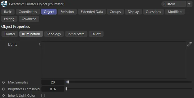
Illumination tab menu.
Lights
Section titled “Lights”Drag the lights you want to control emission into this list.
If there are no lights in the list, no particles will be emitted.
Max. Samples
Section titled “Max. Samples”If you use a spotlight, the emitter will sample the surface of the object in an attempt to find an area which is illuminated.
If the spot is very small, this may take a long time, so this setting controls how many samples are taken before the emitter assumes that the object is not illuminated.
Increase this value if you use a small spot and don’t get many particles being emitted.
Brightness Threshold
Section titled “Brightness Threshold”The angle of incidence of the light rays striking the object surface is compared to this setting.
The threshold value must be exceeded for any particles to be emitted, so the higher this setting, the fewer particles are emitted.
If the light rays strike the surface at just under a right angle, you will need to set this value very low as otherwise it is likely that no particles will be emitted.
But if the light rays are almost parallel to the surface normal, this setting will have no effect unless set very high.
Inherit Light Color
Section titled “Inherit Light Color”If this is checked, the emitted particle will inherit the color of the light falling on the surface.
Object Color tab
Section titled “Object Color tab”This mode lets you control the particle emission and color from the emitting object’s basic color.
This tab is only available when Object Color is selected from the Emit From setting.
Use Color must be set to anything other than Off for this to work.
If it is set to Off, no particles will be emitted.
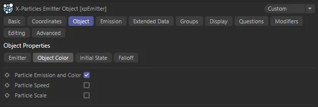
Object Color tab menu.
Particle Emission and Color
Section titled “Particle Emission and Color”If enabled, the object color controls emission from the object and the particle color.
The brighter the color, the more particles are emitted.
If the color is black, no particles are emitted.
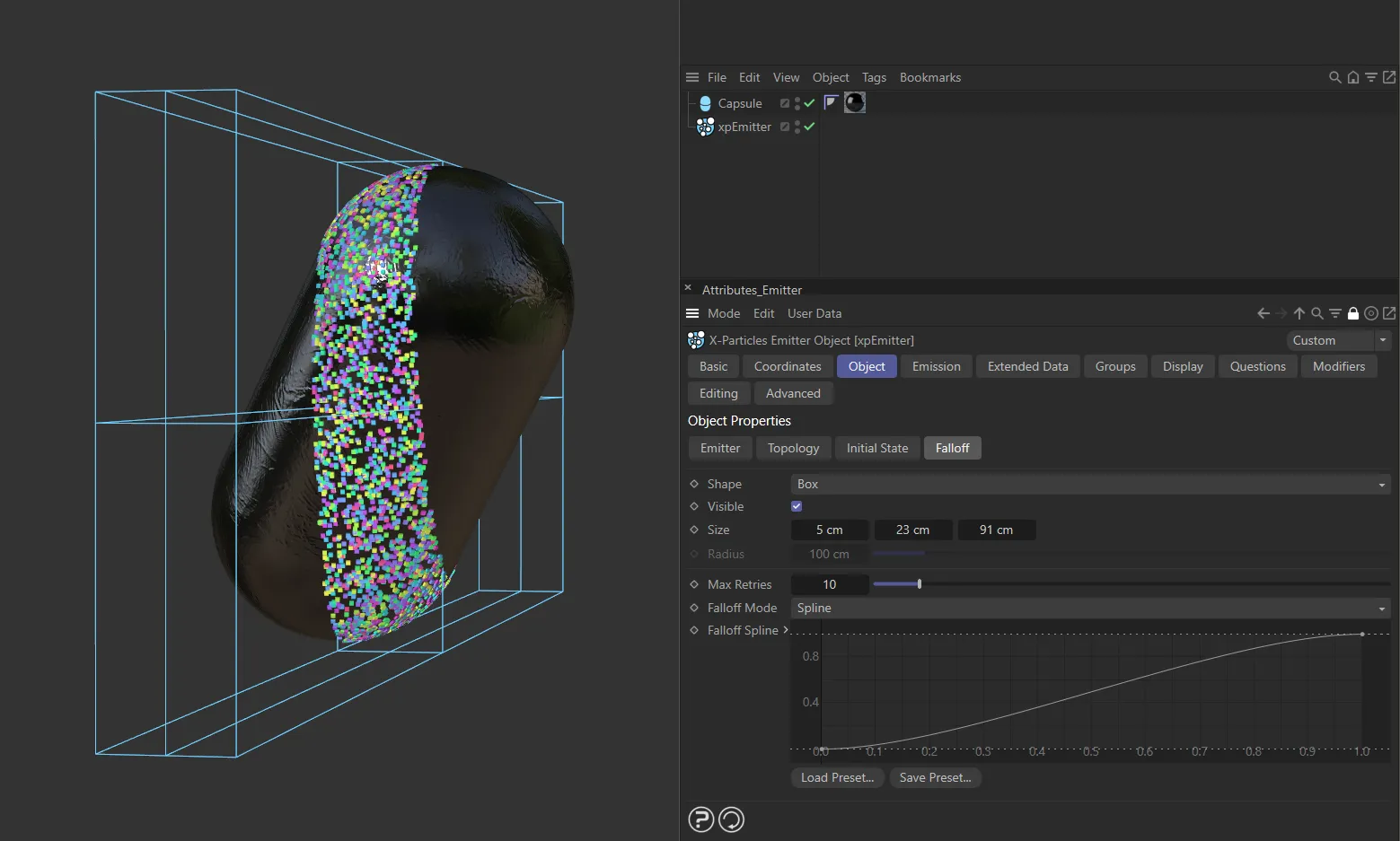
Falloff tab
Section titled “Falloff tab”The X-Particles emitter has its own falloff control.
This is only applicable when emitting from an object.
Normally, the emitter will emit from all polygons (or points or edges) in the object, unless of course this is restricted by a selection tag or when emission is controlled by texture or lights.
What this feature does is allow you to apply a falloff zone to the object so that particles will only be emitted if the emission point is within that zone.
In all cases, the assessment of whether an emission point is within the falloff zone is made before any other effects from selection tags or textures.
This enables you to combine the falloff with other controls on emission: the falloff does not override any other controls.
To use the falloff open the Falloff tab and select a mode other than Infinite.
You can adjust its shape, size and position to cover the areas to emit from.
If the falloff is moved so that it is completely outside the object, or if it is resized so that it is entirely within the object, no particles will be emitted.
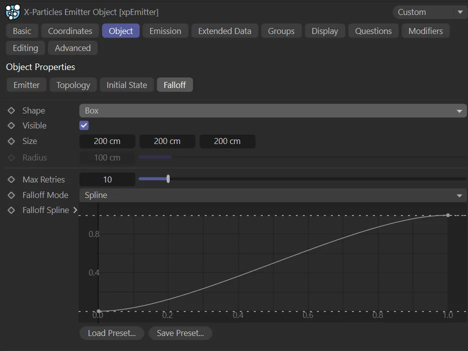
Falloff tab menu.
Set as Infinite by default, the falloff can have different shapes, selected by the options in this drop-down.
The alternatives are: Box and Sphere.
This image shows the falloff Shape setting of Box. A Capsule is intersecting this field and particles are only being emitted on the Capsule area that is within the box itself.
Infinite
Section titled “Infinite”There is no falloff in this setting.
The falloff is a box shape.
The dimensions of each axis of the box can be set individually in the Size parameter.
Sphere
Section titled “Sphere”The shape is a Sphere, whose radius is set in the Radius parameter.
Visible
Section titled “Visible”If enabled, the shape of the falloff will be drawn in the viewport (if Shape is set to Box or Sphere).
The size of the falloff if Shape is set to Box.
You can also use the drag handles to resize it or the Scale tool in Cinema 4D.
Radius
Section titled “Radius”The radius of the falloff if Shape is set to Sphere.
You can also use the drag handles to resize it or the Scale tool in Cinema 4D.
Max Retries
Section titled “Max Retries”If the falloff only intersects a small part of the surface; it is possible that the emitter will take a long time to find a point which is within the falloff.
For this reason, there is a limit on how many attempts the emitter will take to find a point within the falloff; that limit is specified by this setting.
If you find that too few particles are being emitted, you can try increasing this value but it may slow down the simulation.
Falloff Mode
Section titled “Falloff Mode”Set as Spline, by default, the falloff itself has different modes of operation, which are selected by this drop-down menu.
The alternatives are: Boundary and Linear.
Boundary
Section titled “Boundary”If an emission point is within the falloff, a particle will be generated.
If it is not, no particle is generated.
The boundary of the falloff shape acts as a strict cut-off for particle generation.
Linear
Section titled “Linear”In this mode, the probability of generating a particle increases the closer the possible emission point is to the centre of the falloff shape.
This will tend to cluster particles in the nearest area to the falloff with fewer particles emitted at greater distances.
Outside the falloff, no particles will be generated.
Spline
Section titled “Spline”This mode is similar to the Linear mode, but instead of using a simple linear progression the probability of particle emission is controlled by the Falloff Spline control.
This enables you to generate more particles the farther the away the emission point is from the centre of the falloff shape.
Falloff Spline
Section titled “Falloff Spline”The spline control used when Falloff Mode is set to Spline.
Copyright © 2026 INSYDIUM LTD. All rights reserved.