xpBranch
xpBranch creates branching structures, which can be used in an xpTrail object or rendered with the xpSplineMesher.
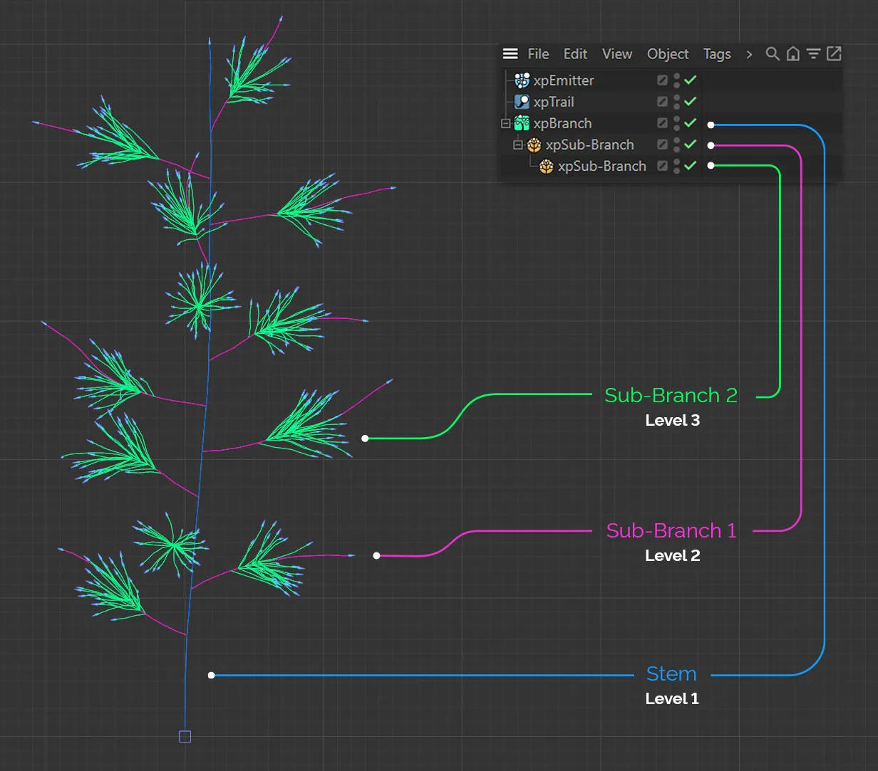
xpBranch is a modifier which produces something akin to a plant structure.
It has a stem, which has branches coming from it and these branches may themselves have branches and so on.
The number, position, length, rotation around the stem, etc. may all be set, procedurally.
The xpBranch modifier itself only produces data used for the stem of the branched object.
To generate actual branches you need a Sub-Branch to be added to it, as a child object.
This can easily be done by clicking the Add Branch Object button.
The Sub-Branch object has a similar button, which you can click to add a sub-branch to the branch.
There is no limit to how many levels are generated but usually from one to three is all that is required.
General tab
Section titled “General tab”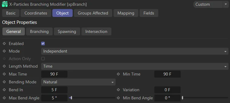
xpBranch General tab.
Enabled
Section titled “Enabled”Checking this box activates xpBranch.
Set at Independent, by default.
You can change this to Action-Controlled.
Independent Mode
Section titled “Independent Mode”In this mode, particles will be affected if they come into the field of effect of the modifier.
Action-Controlled Mode
Section titled “Action-Controlled Mode”When in the Action-Controlled Mode setting, the modifier will only act on a particle when told to do so by an action.
Action Only
Section titled “Action Only”This setting is only available in Action-Controlled mode.
It will force a branch to be generated, when an xpBranch modifier action is triggered which has the Force Branch box checked.
By setting the Branch In setting to longer than the Max Length setting, you can make the modifier only generate a branch when such an action is triggered.
Length Method
Section titled “Length Method”Set to Time, by default, these length settings can be expressed in terms of time or distance.
The alternative setting is Distance Units.
The modifier will set the maximum length of the initial ‘stem’ of the branched object using the method in this drop-down.
The stem will have a length randomly selected between the Max Length and Min Length parameters.
The length is expressed in terms of elapsed time.
The default is set to 3 seconds.
Distance Units
Section titled “Distance Units”The length is expressed in terms of scene units.
The default is set to 450 units (the distance traveled by a particle in 3 seconds at the default speed of 150 units/second).
You can use whichever setting meets your needs; it only changes the units used - there is no effect on the final result.
Max Time, Min Time/Max Distance, Min Distance
Section titled “Max Time, Min Time/Max Distance, Min Distance”These are the upper and lower limits of the stem length.
The units of these parameters will change depending on the Length Method setting.
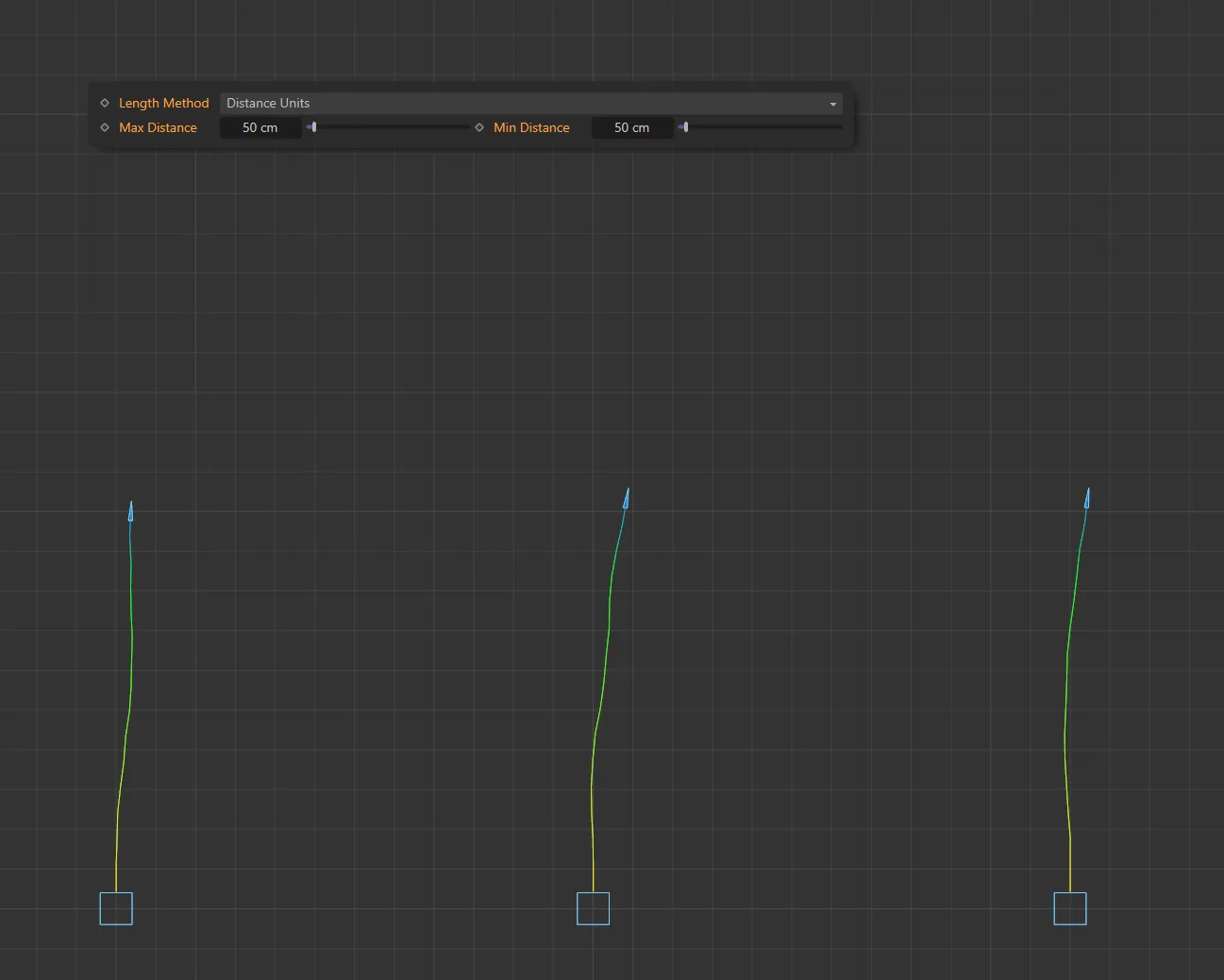
With the Length Method set as Distance Units, this first image shows three branch structures with both Max Distance and Min Distance values of 50cm.
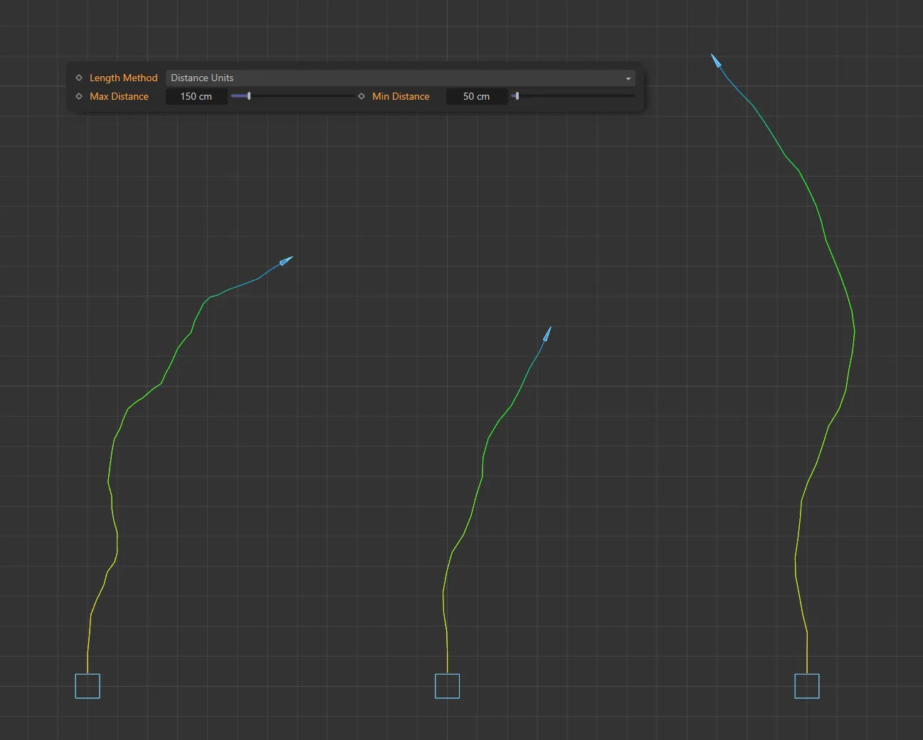
In this second image, the Min Distance is still 50cm but the Max Distance is now 150cm, giving different lengths between the two values.
Bending Mode
Section titled “Bending Mode”Set as Zigzag, by default, the stem will deviate from its initial course as it grows.
The other settings are: Natural and Curl.
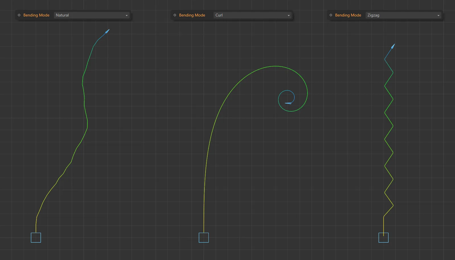
Here are the Bending Mode settings of: Natural, Curl and Zigzag.
Zigzag
Section titled “Zigzag”Each bend is in the opposite direction to the previous one, so the growth has a zigzag appearance.
Natural
Section titled “Natural”The stem or branch grows in a natural fashion.
Different looks can be achieved by changing the Random Seed value in the Advanced tab of the xpEmitter.
In this mode the branch will curl as it grows.
If you choose this mode, additional parameter settings become available (below).
Bend In, Variation
Section titled “Bend In, Variation”The time between bends in the stem.
The smaller the value, the more bends occur.
Variation to the time can be added with the Variation setting.
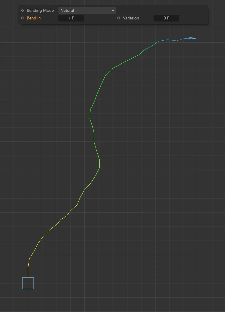
Bend In is set to 1 frame, in this image.
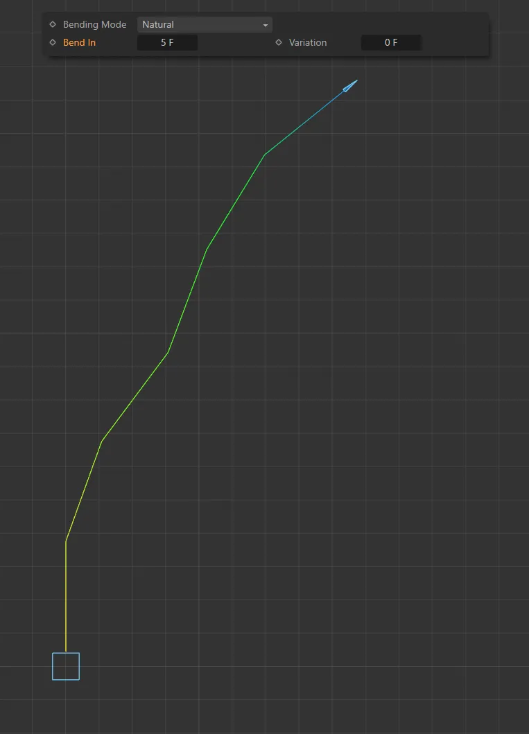
Bend In increased to 5 frames, giving less bends.
Max Bend Angle, Min Bend Angle
Section titled “Max Bend Angle, Min Bend Angle”The degree of bending is randomly chosen between these values.
The maximum possible value is 90 degrees.
Set these values to zero to remove any bending.
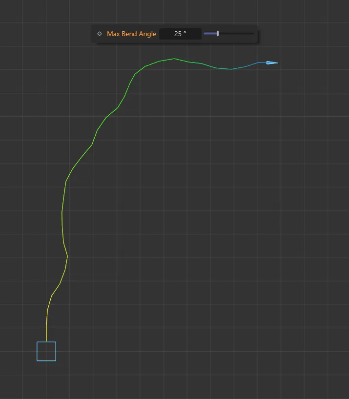
Max Bend Angle set at 25 degrees.
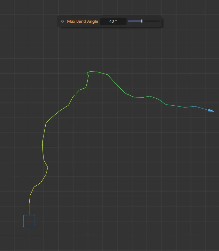
Max Bend Angle increased to 40 degrees.
Curl mode additional settings
Section titled “Curl mode additional settings”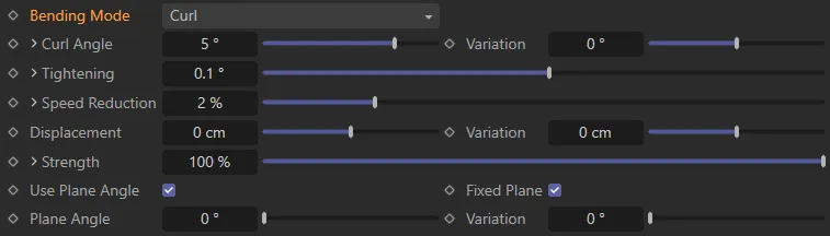
Additional parameter settings with Bending Mode set as Curl.
Curl Angle, Variation
Section titled “Curl Angle, Variation”This is the degree of curl.
The higher the value, the faster the branch will curl.
It is recommended that, in most cases, this value should be kept low, below 5 degrees.
You can add some variation between branches with the Variation setting.
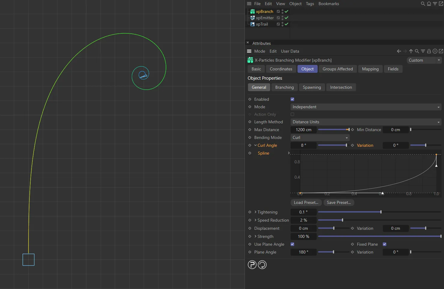
If you click the little arrow to the left of the Curl Angle parameter, you have access to a control spline.
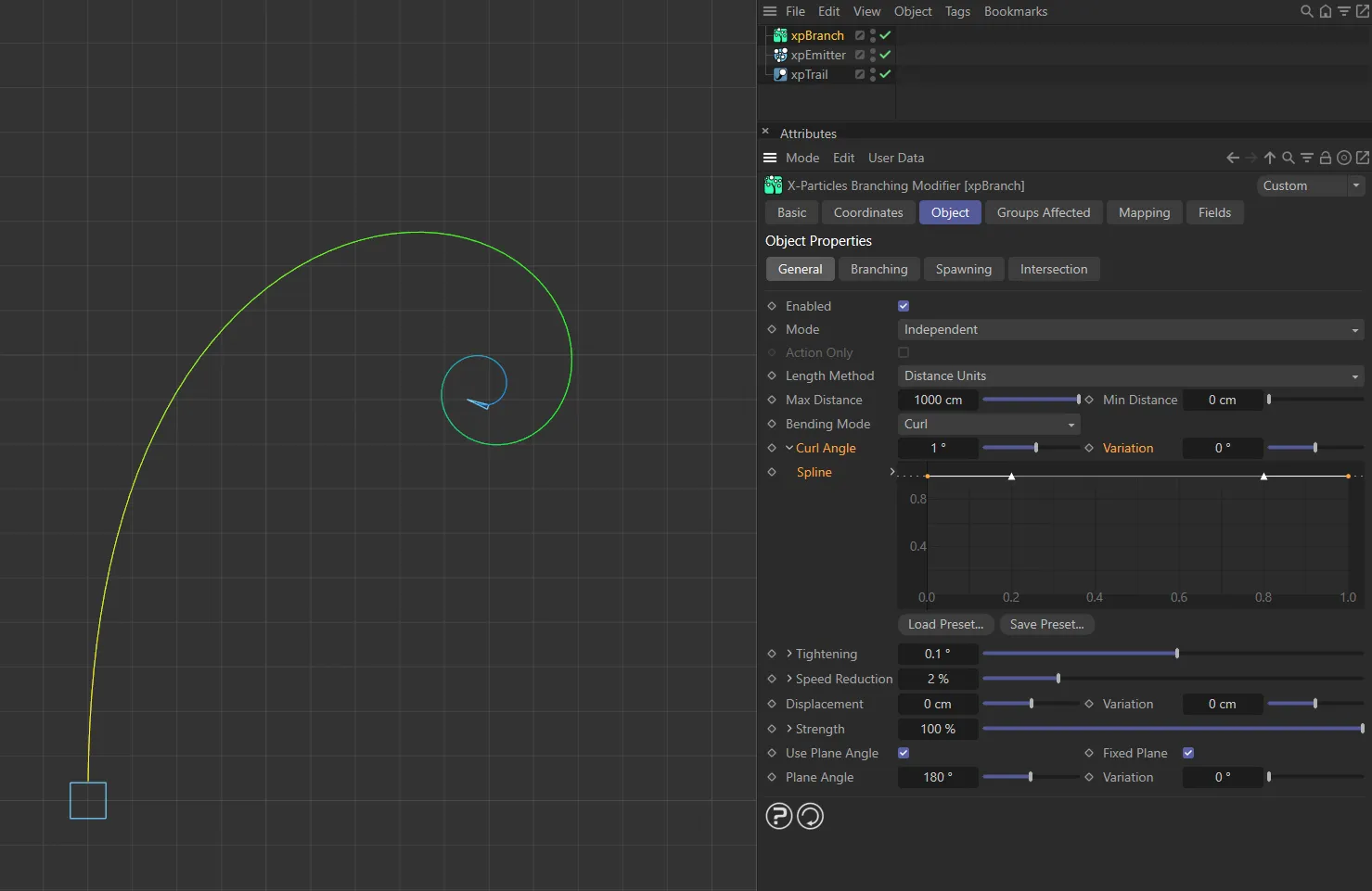
Here, the Curl Angle is set to 1 degree.
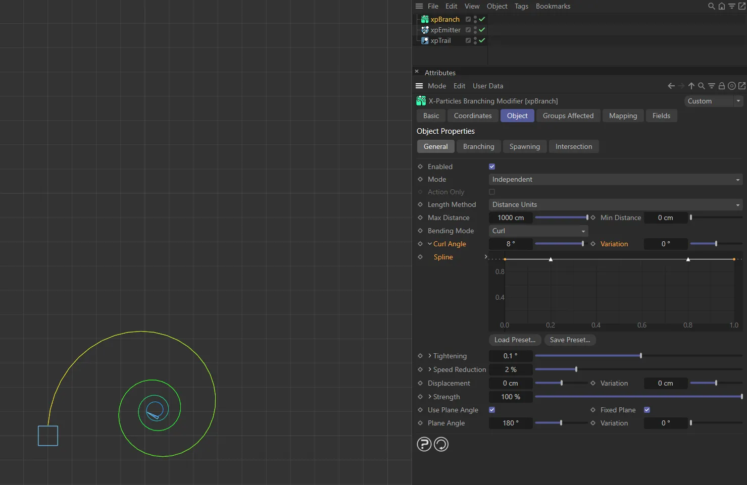
The Curl Angle is raised to 8 degrees in this second image.
Spline
Section titled “Spline”This lets you control the curl angle over the length of the branch so you could, for example, have a light curl at the start but a tighter one towards the end.
With this custom Spline setting, the curl angle is increasing over the length of the spline.
Tightening
Section titled “Tightening”As the branch grows, the value in this setting is added to the curl angle, so the curl becomes tighter and tighter as the branch grows.
If this is set too low, the amount of curl may be very small, producing a soft bend rather than a curl.
This setting normally requires only a small value as the curl angle will be increased by this value each frame.
As with Curl Angle, clicking the little arrow reveals a control spline.
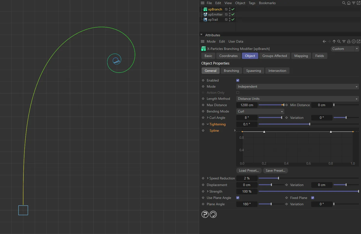
Tightening set at 0.1 degrees.
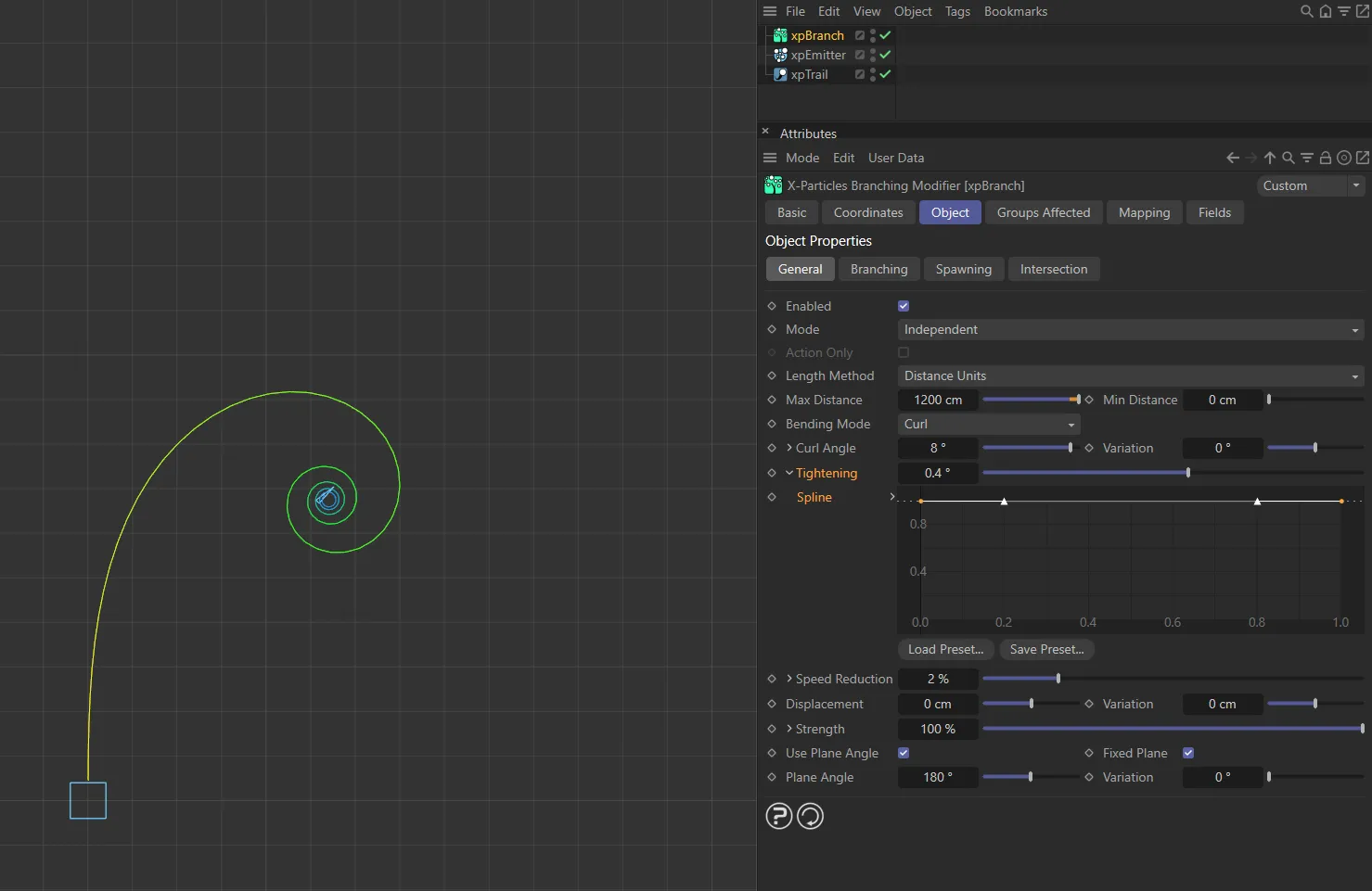
In this image, the Tightening is 0.4 degrees.
Spline
Section titled “Spline”This lets you control tightening over the length of the branch.
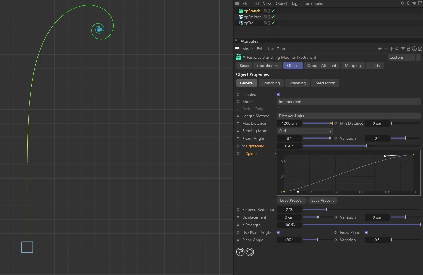
The Tightening is still set at 0.4 here, but now the Spline setting is increasing the tightening over time.
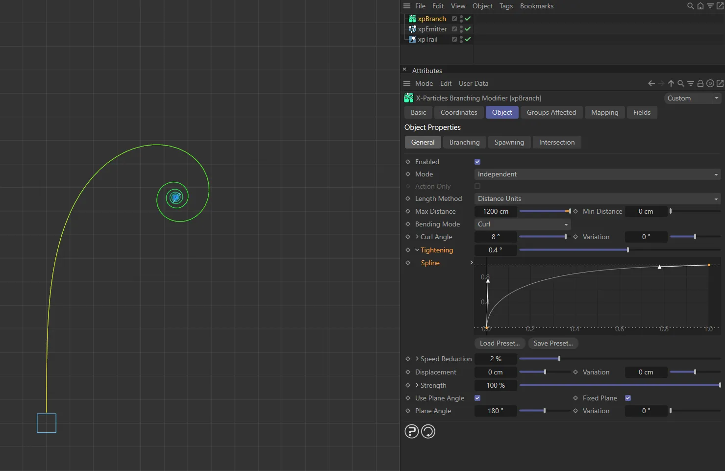
The custom Spline setting, in this image, is driving an earlier increase in the tightening. This is now showing a similar shape to the image above, but with a tighter spiral towards the end of the spline.
Speed Reduction
Section titled “Speed Reduction”As the branch grows, the particle speed is reduced by this amount each frame.
If you don’t do this, as the branch curls, the distance it travels each frame remains the same and the result is a curl which never reaches a center point.
If this is too high, the speed approaches zero and the branch stops growing.
Again, clicking the little arrow reveals a control spline.
Spline
Section titled “Spline”This spline is to control speed reduction over the length of the branch.
Displacement, Variation
Section titled “Displacement, Variation”Normally the curl all takes place in one arbitrary plane.
With this setting, you can force the curl to move out from that plane to produce a spiral or helix.
You can add variation to the displacement with the Variation setting.
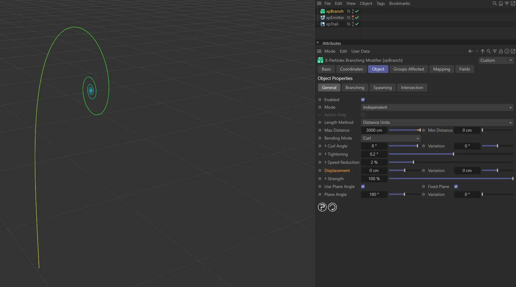
Displacement of 0 (zero) cm.
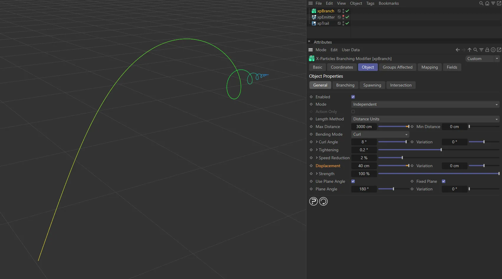
Displacement value increased to 40cm, creating a spiral towards the Z axis.
Strength
Section titled “Strength”The overall strength of the curl effect.
If this is set to zero, there will be no curl effect at all.
Once again, clicking the little arrow reveals a control spline.
Spline
Section titled “Spline”This spline is to control the strength over the length of the branch.
Use Plane Angle
Section titled “Use Plane Angle”If this parameter is unchecked, all branches curl in a randomly-selected plane.
If it is checked, you can choose any arbitrary plane for the branches, using the Plane Angle and Variation settings.
By default, this is enabled, so each branch will always curl in a fixed plane.
If you uncheck this setting, the plane is selected randomly and will vary according to the direction of the particle from which a branch is generated.
This can lead to results that may look very interesting but may also show no curl at all.
For that reason, it is recommended that you leave this enabled.
Fixed Plane
Section titled “Fixed Plane”Only available if Use Plane Angle is enabled.
This forces the branch to set a fixed plane for the curl even if the Plane Angle subsequently changes.
If it is disabled, the curl plane is recalculated each frame and if the Plane Angle has changed, the curl plane will change.
This leads to the curl ‘unwinding’, rather than being held to one plane.
This can look very effective but, as with Use Plane Angle, it is recommended that you leave this enabled unless you are confident about how this mode works.
In such a case, Fixed Plane is always on to allow the creation of symmetrical curls.
Plane Angle, Variation
Section titled “Plane Angle, Variation”Only available if Use Plane Angle is enabled.
It is the plane angle to use if Use Plane Angle is checked.
Variation can be added with the Variation setting.
Branching tab
Section titled “Branching tab”This section contains the parameters for the branches from the initial stem.
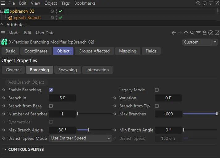
xpBranch Branching tab.
This second image shows the UI for a Sub-Branch object.
Add Branch Object
Section titled “Add Branch Object”This button will add a Sub-Branch object to the xpBranch modifier. The settings for the Sub-Branch object can be found further down the page.
You must do this before any branches are generated.
Once you have added a sub-branch, this button is unavailable since only one Sub-Branch object per branch level is permitted.
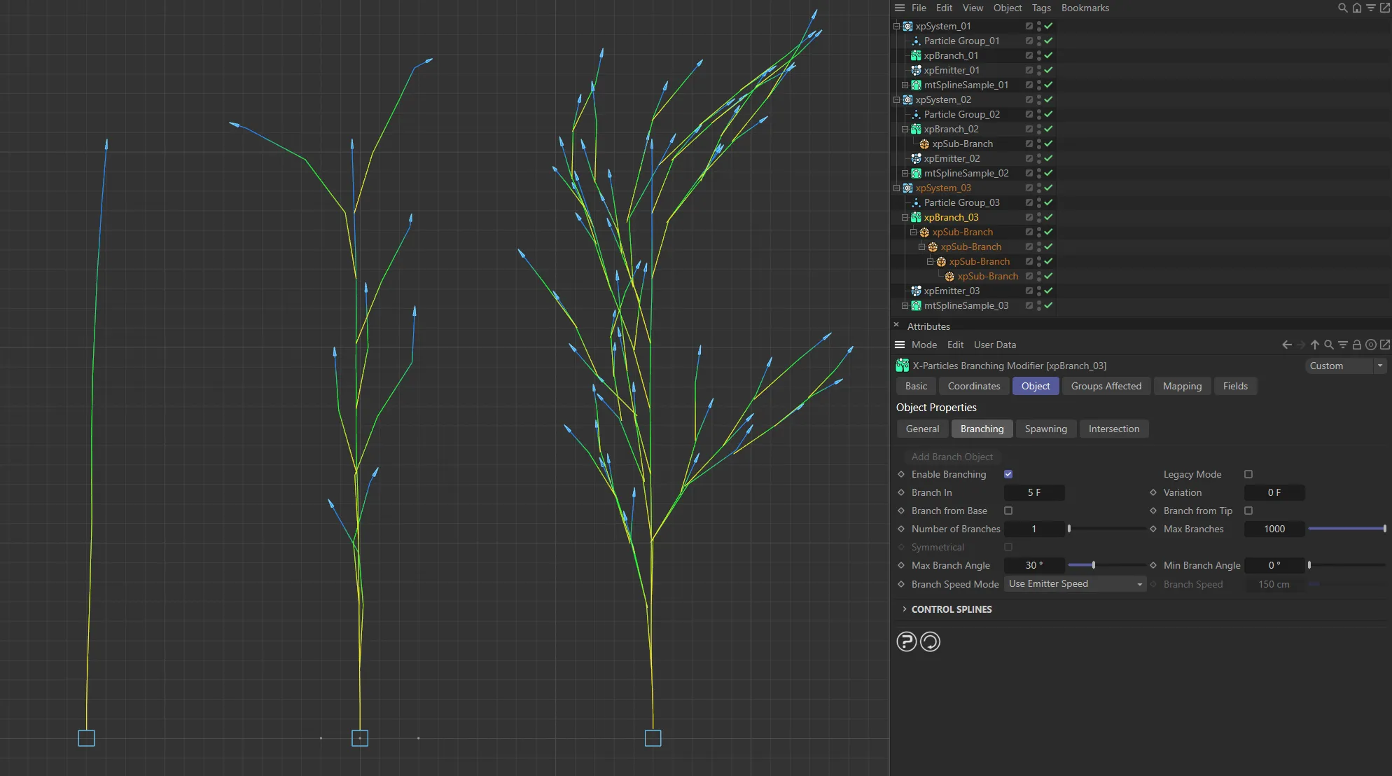
In this image, the first object has no branches, the second has one Sub-Branch object and the third has four Sub-Branch objects.
Enable Branching
Section titled “Enable Branching”Disabling this will disable branching from the stem and branching from any sub-branches (the entire hierarchy is disabled).
Legacy Mode
Section titled “Legacy Mode”Enabling will give a more controllable result when using the Branch In and Variation settings.
If you have existing scenes whose branch structure you want to preserve, check this box; the previous algorithm will then be used instead.
Branch In, Variation
Section titled “Branch In, Variation”The time between branches from the stem.
The smaller the value, the more often a branch is generated.
Variation to the time can be added with the Variation setting.
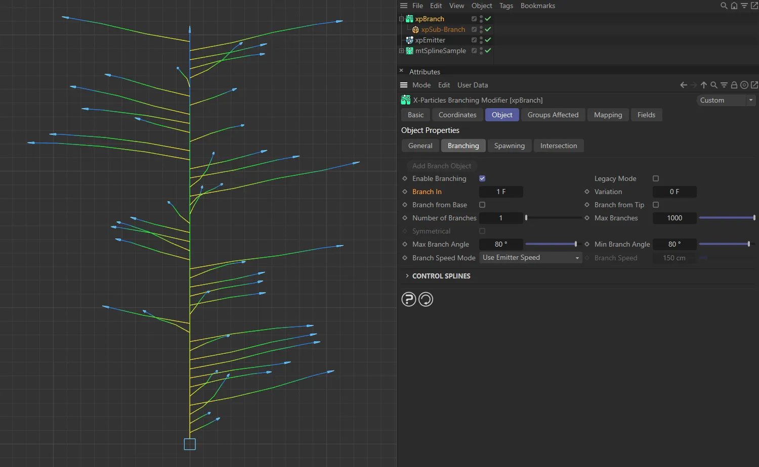
Branch In set to 1 frame, with a branch being generated every frame.
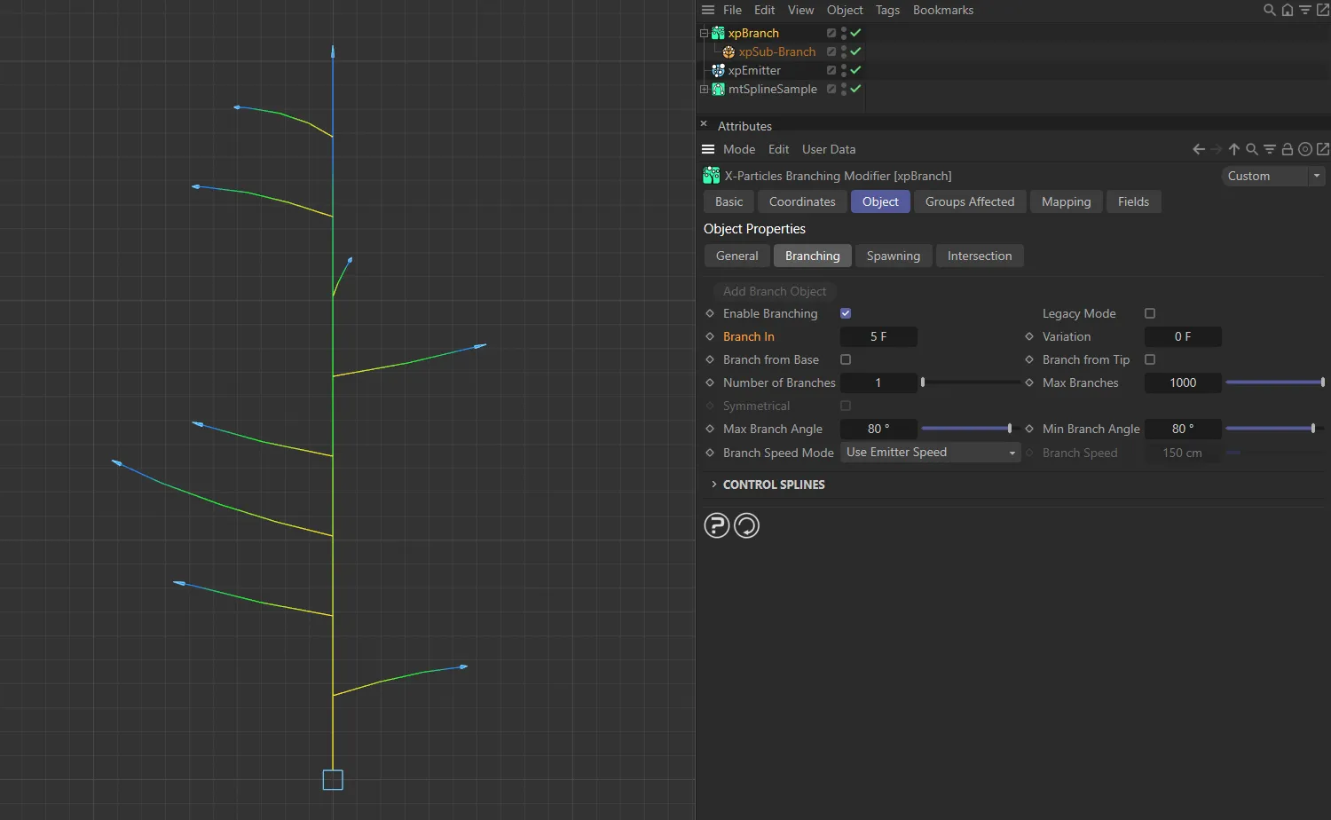
In this image, Branch In is set to 5 frames, now generating less branches.
Branch from Base, Branch from Tip
Section titled “Branch from Base, Branch from Tip”These parameters, if enabled, force the modifier to branch from the base and/or the tip of the stem.
If they are unchecked, branching from the base will never occur; branching from the tip may occur but only if the animation time happens to coincide with the time the modifier would branch at anyway.
Number of Branches
Section titled “Number of Branches”This is the number of branches that will be generated (at the same starting point on the stem or parent branch) each time branching occurs.
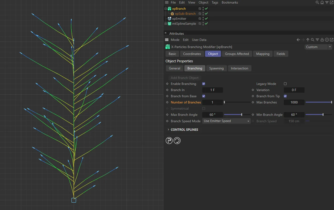
Number of Branches set to 1.
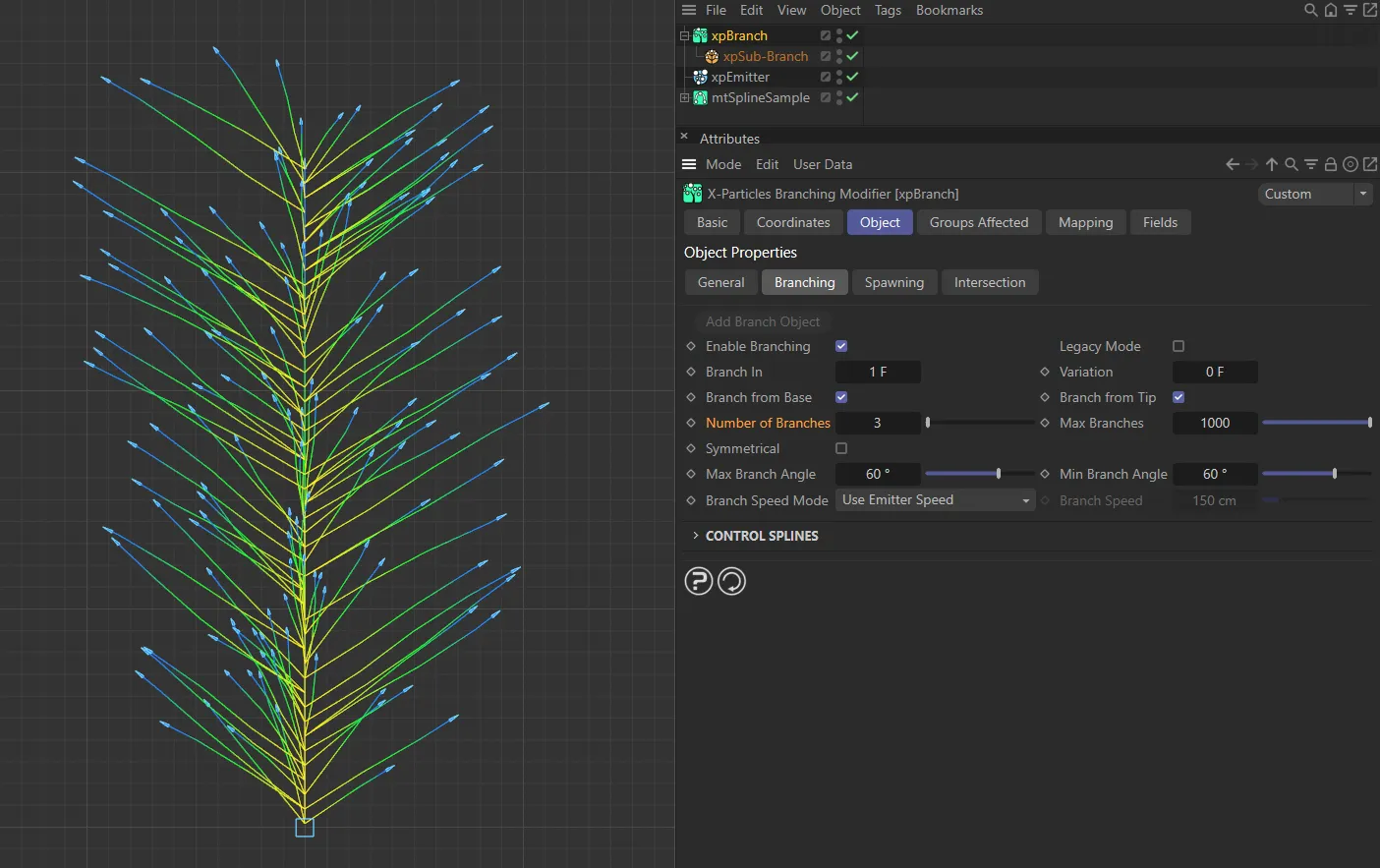
Number of Branches now raised to 3.
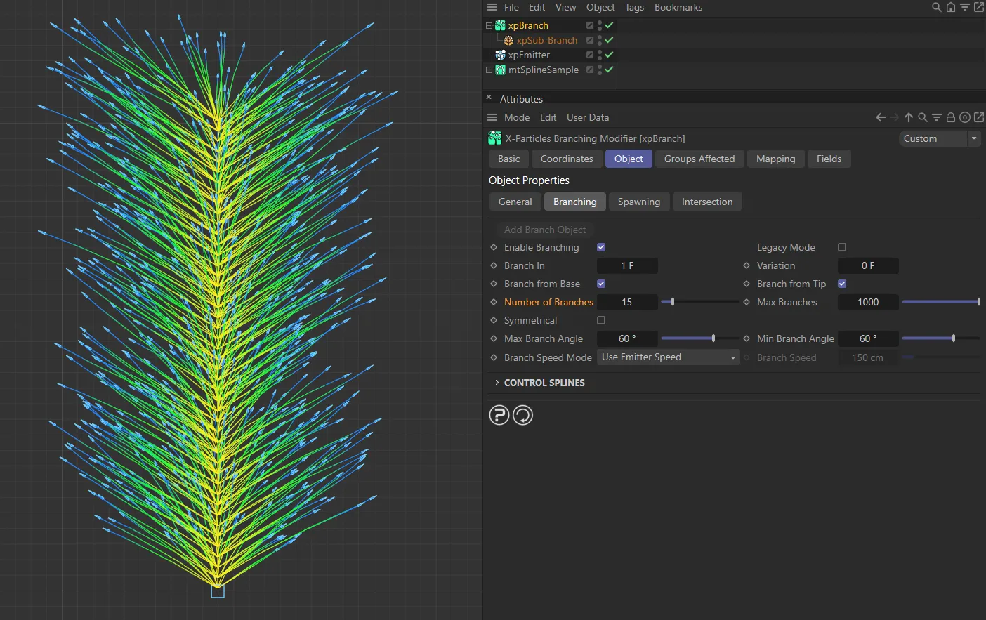
Finally, here Number of Branches is set to 15.
Max Branches
Section titled “Max Branches”The maximum number of branches that will be generated.
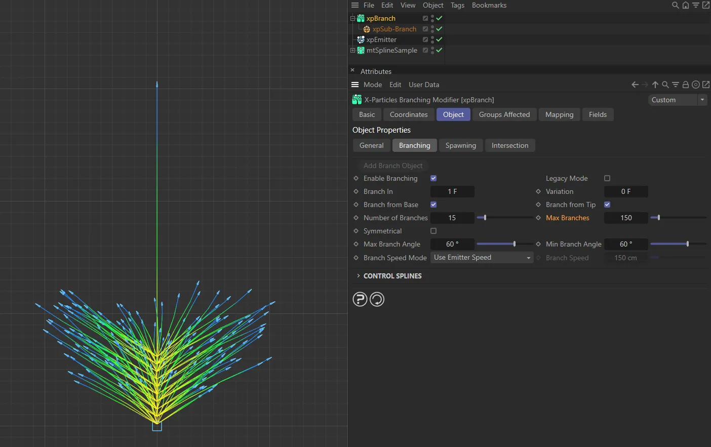
In this image, Max Branches is set to 150.
Symmetrical
Section titled “Symmetrical”This setting is only available if Number of Branches is set to at least two.
If you set Rotation Mode to Set Angle, all branches emerge from the stem at the same angle.
If, for example, you have set Number of Branches to two, you won’t see any effect because the two branches both follow the same direction.
By enabling this parameter, you can achieve a symmetrical effect so that, if the number of branches is set to two, the two branches emerge opposite one another.
If the number of branches is six, the six branches will be evenly spaced around the stem.
You can use this mode to create structures such as feathers.
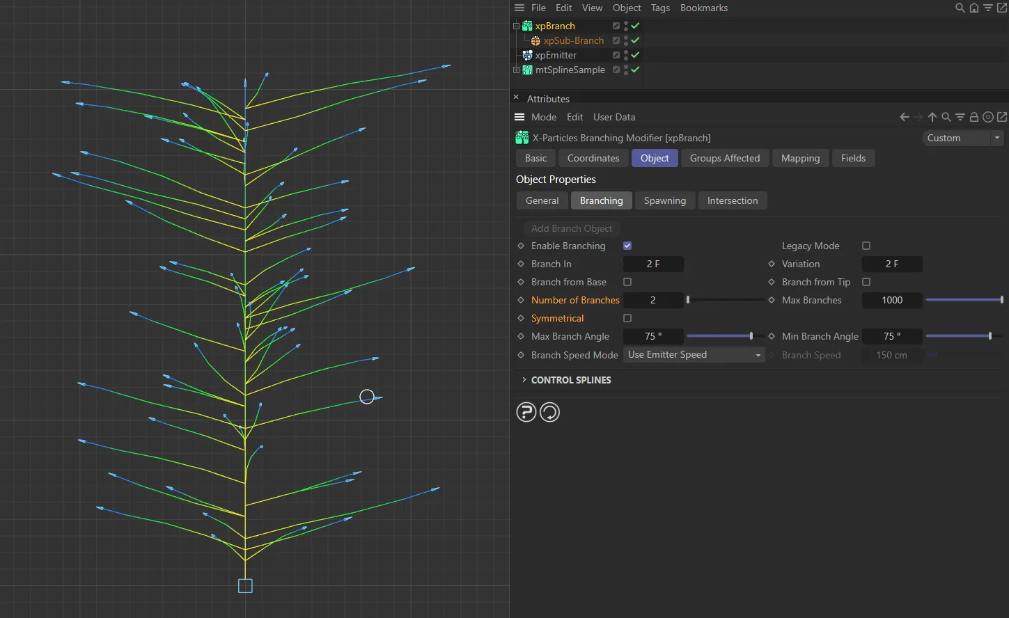
Symmetrical is disabled in this first image.
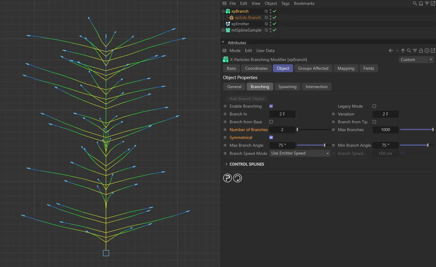
Symmetrical enabled here, with the clear symmetrical result.
Max Branch Angle, Min Branch Angle
Section titled “Max Branch Angle, Min Branch Angle”The degree of deviation of the branch from the stem is randomly chosen between these values.
The maximum possible value is 90 degrees.
Branch Speed Mode
Section titled “Branch Speed Mode”Set as Use Emitter Speed, by default, this drop-down controls the speed of the newly-generated particle which forms the new branch.
The alternative options are: Source Particle Speed and Set Speed.
Use Emitter Speed
Section titled “Use Emitter Speed”The speed given by the emitter will be used.
If a particle group is specified in the sub-branch object, the speed given in that group will be used; otherwise the speed given in the emitter itself is used.
Source Particle Speed
Section titled “Source Particle Speed”The speed will be set to the same as the particle which generated the branch.
Set Speed
Section titled “Set Speed”The value in the Branch Speed parameter will be used.
Branch Speed
Section titled “Branch Speed”The speed of the branch particle, if Branch Speed Mode is set to Set Speed.
Control Splines
Section titled “Control Splines”There are three splines to control branch distribution, length, and angle of rotation.
Distribution
Section titled “Distribution”This spline controls the distribution of branches along the stem.
A value of zero means that no branch will occur at that point; a value of 1.0 means that a branch will occur,
This value is then multiplied with the number of branches from the modifier’s interface to determine how many branches to generate at that point.
If the number of branches is 1 and the value from the spline is less than 1.0, no branches are emitted.
This is because the number of branches must be a whole number and if the number of branches is 1 and the spline value is (for example) 0.4, the result is 1 x 0.4 = 0 (again, the number of branches must be a whole number).
If the number of branches is 3, then you would actually get 3 x 0.4 = 1.2 = one branch.
Therefore, if you are using the distribution curve, you should increase the number of branches to more than one, or all the branches may disappear.
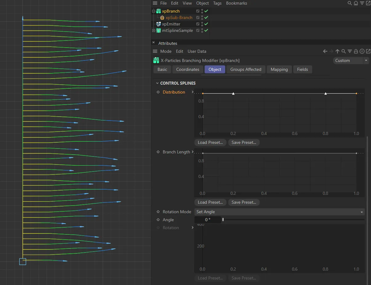
The following six images mainly have Number of Branches set to 1, the Rotation Mode is Set Angle with an Angle of 0 (zero) degrees. This first image has the default Distribution spline setting, with branches distributed over the entire source branch.
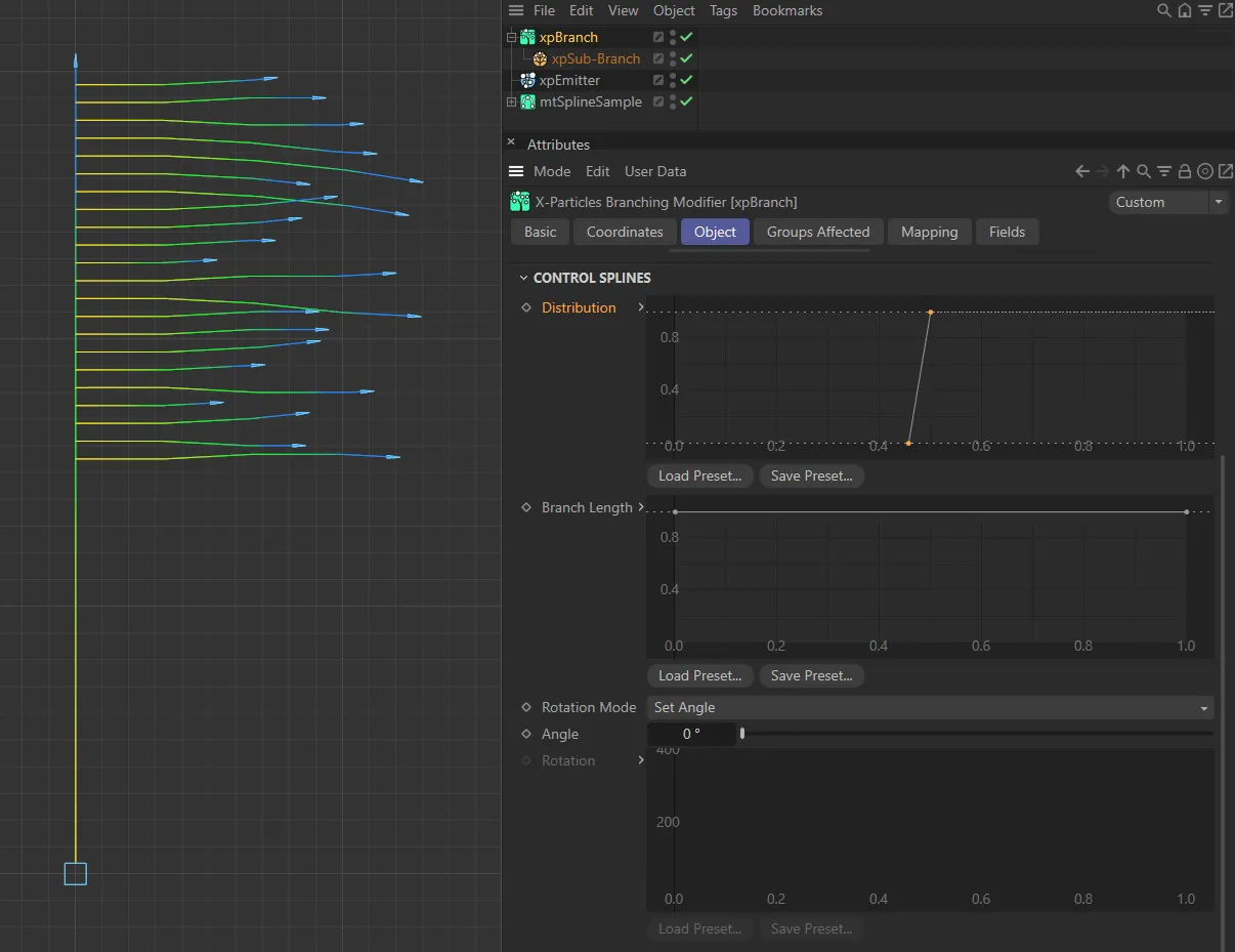
This custom Distribution spline setting means there are no branches beneath the half way point, then branches appear afterwards.
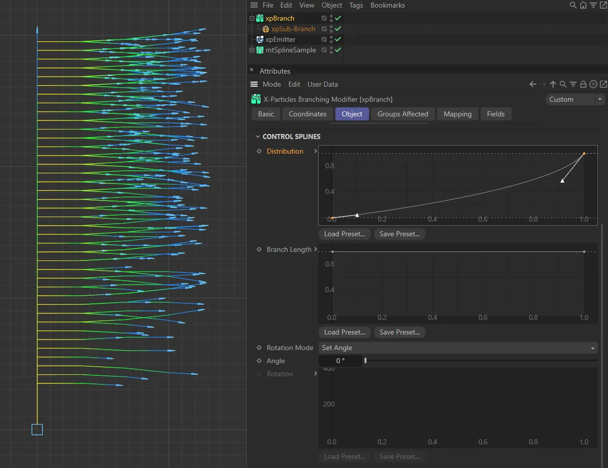
Number of Branches is increased to 20, in this image. The user spline used for Distribution means that the additional branches also increase in their distribution towards the top of the base branch.
Branch Length
Section titled “Branch Length”This is a scale spline which affects the length of the branches.
It scales the value given in the branch length setting in the Sub-Branch object (not this modifier).
You can use this to have long branches near the base and short ones at the tip, for example.
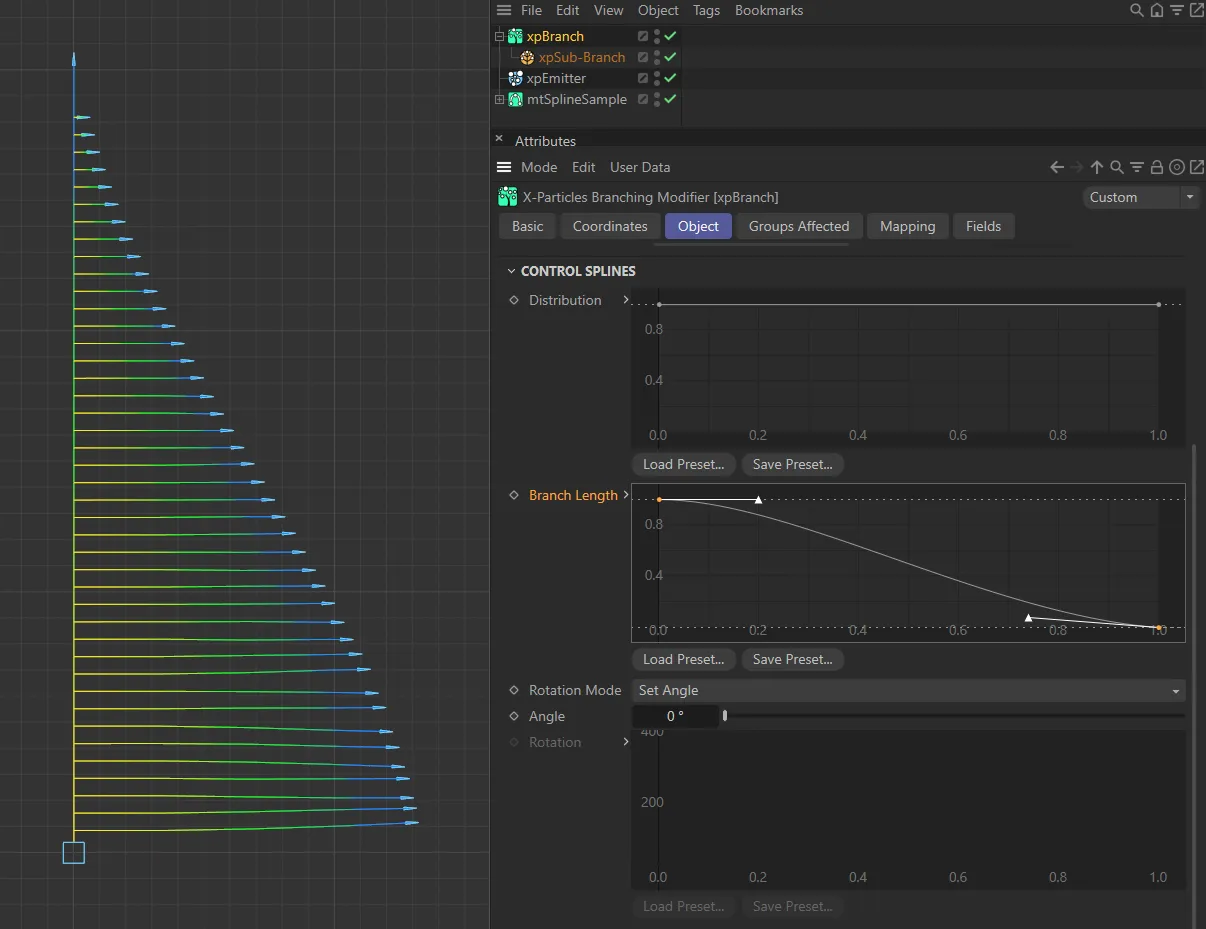
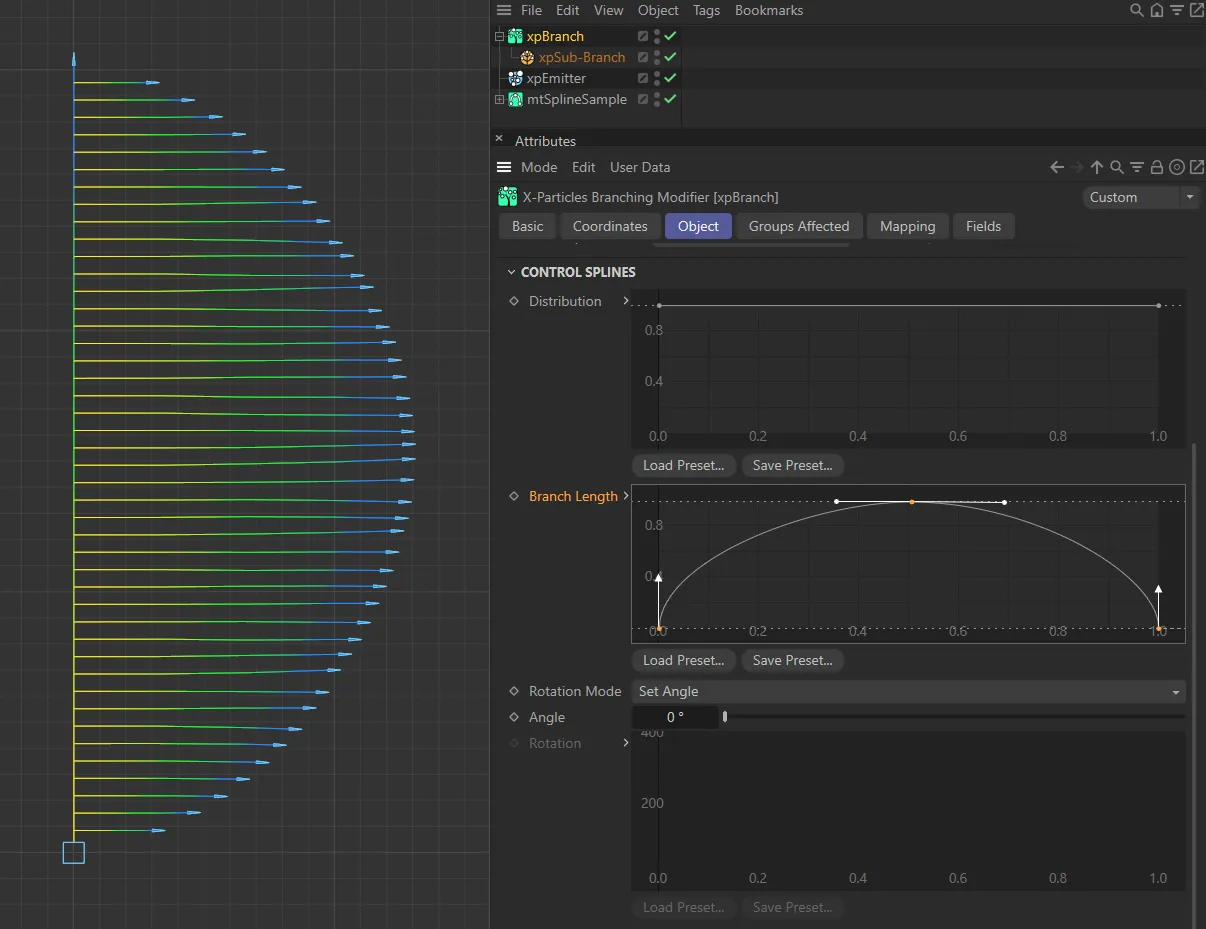
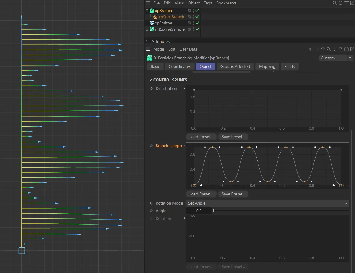
With the same settings as above, the three customized Branch Length spline settings are mirroring the branch lengths created in these three images.
Rotation Mode
Section titled “Rotation Mode”Set as Random, by default, this governs the angle around the branch at which the branch emerges from the stem.
If you imagine a 360 degree circle around the stem, this is the point on that circle where the branch originates.
The other available settings are: Use Spline, Random Then Spline, Set Angle and Set Angle Then Spline.
Random
Section titled “Random”The branches will be generated from a random angle around the stem.
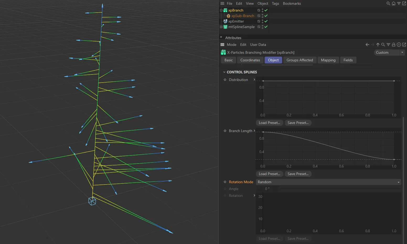
Rotation Mode set as Random.
Use Spline
Section titled “Use Spline”The spline will control the angle completely.
The spline angle at the point the branch occurs is not an absolute value; it is an incremental value, added to the previous angle.
For example, if you set the spline to have a constant value of 30 degrees, each time a branch is generated it will be rotated 30 degrees around the stem from the previous branch.
This enables you to generate a completely regular structure around the stem.
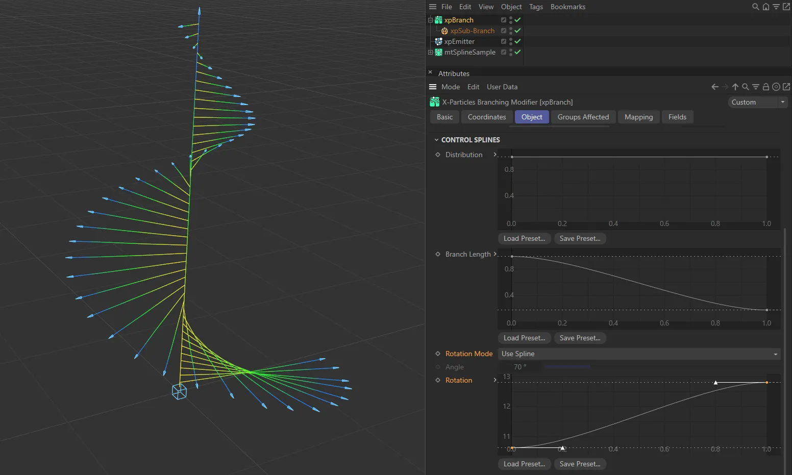
Rotation Mode set as Use Spline, with the Rotation spline setting driving the generation of the branch..
Random Then Spline
Section titled “Random Then Spline”The modifier will first select a random angle around the stem and will then generate a branch.
For all subsequent branches the angle will be incremented by the angle in the spline at that point along the stem.
Set Angle
Section titled “Set Angle”The angle is given by the value in the Angle parameter.
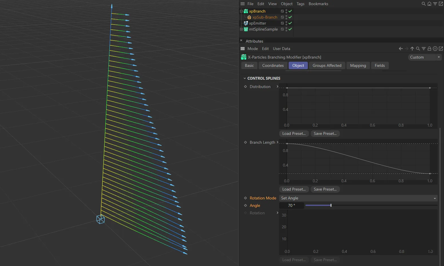
With the Rotation Mode of Set Angle, the Angle set, here, is 70 degrees.
Set Angle Then Spline
Section titled “Set Angle Then Spline”The modifier will first set the angle around the stem from the Angle parameter and will then generate a branch.
For all subsequent branches the angle will be incremented by the angle in the spline at that point along the stem.
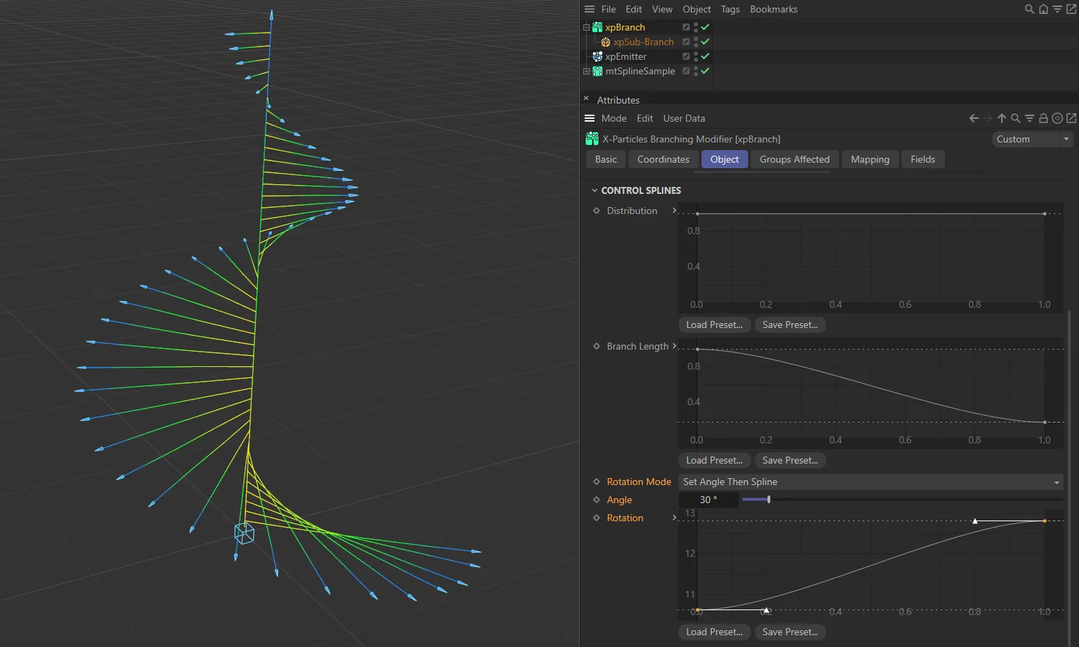
In this image, the Rotation Mode is Set Angle Then Spline. The Angle set is 30 degrees and the Rotation spline is driving the shape of the rotation.
The angle used in the Set Angle and Set Angle Then Spline modes.
Rotation
Section titled “Rotation”The control spline used for controlling rotations.
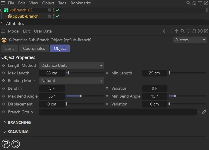
Sub-Branch Object
Section titled “Sub-Branch Object”This object is required when adding a branch level to an xpBranch modifier.
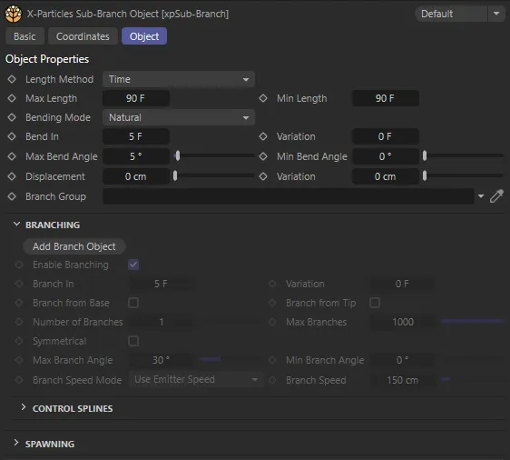
Sub-Branch object menu settings.
Most of the settings in this object are identical to those with the same name in the xpBranch modifier.
There are some small differences, which are detailed here.
Branch Group
Section titled “Branch Group”You can specify that particles in this branch object belong to a different group from the source particle.
This is useful if you want different branch levels to be affected by different modifiers, such as an xpGravity modifier.
Add Branch Object
Section titled “Add Branch Object”This button will add another Sub-Branch object to this Sub-Branch object as a child object of it.
Once you have added a sub-branch, this button is unavailable since only one sub-branch object per branch level is permitted.
Spawning tab
Section titled “Spawning tab”You can spawn from the particle used in the stem, with these settings.
If you also want to spawn from the branched particles, these same settings are used, but you will also need to enable spawning in the Sub-Branch object.
For spawning to work correctly, the xpBranch modifier must be added to the modifiers list of the spawning emitter.
This will be done automatically if you use the Add Emitter button (in this Spawning tab) or if you drag an emitter into the Spawning Emitter link field.
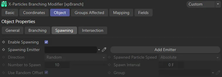
xpBranch Spawning tab.
Enable Spawning
Section titled “Enable Spawning”Check this box to enable spawning from the stem particle.
Spawning Emitter
Section titled “Spawning Emitter”The emitter used to generate spawns.
This should not be the same emitter whose particles are generating the branches.
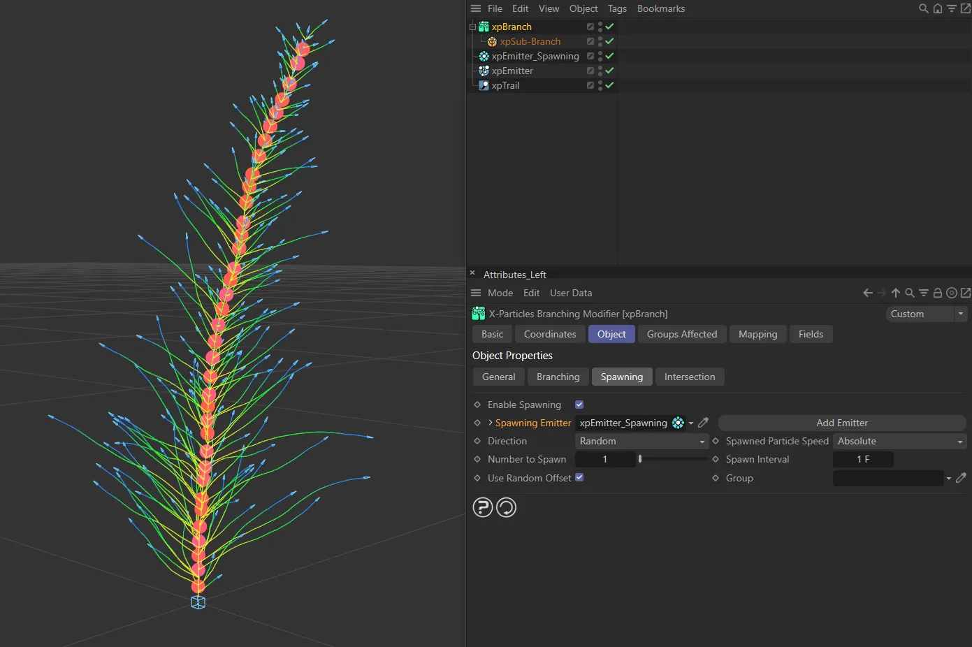
In this image, particles are being spawned with no speed. The xpBranch Spawning Emitter is linked to a unique xpEmitter, which is generating particles along the main stem.
Add Emitter
Section titled “Add Emitter”Click this button to create a new emitter and add it to the Spawning Emitter link field.
Direction
Section titled “Direction”Set as Random, by default, this is how the direction of the spawned particles is determined.
The alternative setting is Source Particle.
Random
Section titled “Random”The direction of the spawned particles is set to a random value which, in practice, means that the spawns adopt a spherical distribution.
In this animation, with the same emitter setting as above, except speed now set on the particle emissions, Direction is set to Random.
Source Particle
Section titled “Source Particle”In this mode the direction of the new particles is the same as the source particle.
The settings are same in this scene, with Direction now changed to Source Particle.
Spawned Particle Speed
Section titled “Spawned Particle Speed”Set as Absolute, by default, this option controls the speed of the spawned particles.
The alternative setting is Relative.
Absolute
Section titled “Absolute”The spawned particle speed is determined by the spawning emitter.
Relative
Section titled “Relative”The spawned particle speed is the sum of the source particle speed and the speed from the spawning emitter.
If the spawning emitter sets a speed of zero, the spawns will have the same speed as the source particle.
Number to Spawn
Section titled “Number to Spawn”The number of particles to spawn each frame.
Spawn Interval
Section titled “Spawn Interval”The time interval between spawns.
Set this to zero to spawn new particles each frame.
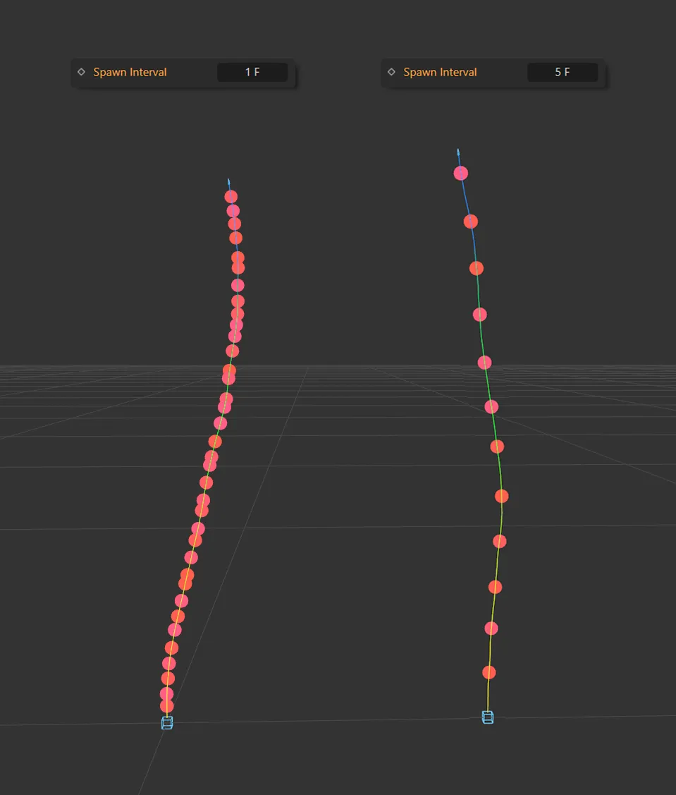
The Spawn Interval on the left is every frame. By comparison, on the right, the Spawn Interval setting is every 5 frames.
Use Random Offset
Section titled “Use Random Offset”If enabled, a small offset (derived from the particle radius) is applied along the spawned particle’s direction of travel.
This is to prevent a too-regular appearance of the spawns.
If you prefer the appearance to be regular, uncheck this box.
Spawned particles can be assigned a new group.
Drag the Group object, you want to use, into this link field.
Intersection tab
Section titled “Intersection tab”The xpBranch modifier can detect intersections with other branches and take action if a potential intersection is detected.
In this first animation, Check Intersections is disabled. The stem curls around onto itself and the branches intersect.
By comparison, in this scene, Check Intersections is enabled. When the particle is within 100cm of the xpTrail, it changes direction and triggers an action (as seen in the Layers list). The action (in the Actions list) is a Change Scale Action, from 0.25cm radius to 2cm. This action also includes a change in particle color and shape. Therefore, the source particle changes appearance and direction when within 100cm of the xpTrail.
Check Intersections
Section titled “Check Intersections”Checking for intersections is computationally-intensive.
Only chck this box if you want to detect, and respond to, potential intersections.
Detection Distance
Section titled “Detection Distance”The maximum distance at which a potential intersection will be detected.
There is little point in detecting all possible intersections, no matter how far away, since a branch may change direction in the meantime.
Default Thickness
Section titled “Default Thickness”This setting has two uses.
Since the xpTrail object is a spline, this is the ‘thickness’ given to the trail.
A spline has zero thickness, so there is nothing to collide with; in that case, the spline has to be given an assumed thickness to provide a collision object.
In this modifier, this object is always an X-Particles Trail object, as opposed to a conventional spine.
Therefore, its thickness comes from the Thickness and Color tab of the xpTrail object.
That tab can do three things:
- the default is that the thickness is not set, in which case it is given a default value of 0.5 scene units and this default thickness setting is ignored
- the thickness is specifically set, in which case this setting is again ignored
- or the No Thickness or Color Data setting is enabled, in which case no thickness data at all is provided by the xpTrail object and this setting provides the thickness value.
There is another use.
When a particle is trying to avoid its own xpTrail object, the problem is that the trail has the virtual ‘cylinder’ around it.
This means that if you test for intersections from the particle position, it will hit the cylinder around itself and register an instant hit, which is clearly incorrect.
If it tries to change direction at that point, it won’t be able to because the ‘cylinder’ completely surrounds it, so it fails to determine a suitable new direction and simply stops.
The only way around this is to advance the starting position along its direction of travel until the starting position is ‘outside’ the virtual cylinder.
The Default Thickness value is used for this purpose, advancing the start position of the ray by that distance along the direction of travel.
It is strongly recommended that you enable No Thickness or Color Data in the xpTrail object.
This will then ignore all thickness data from the xpTrail object and use only the value in this setting.
On Intersection
Section titled “On Intersection”Set as Change Direction, by default, this enables you to choose what the particle will do when it detects a possible collision with an xpTrail object from the Trails list.
The alternative settings are: Freeze, Die and Trigger Actions.
Change Direction
Section titled “Change Direction”The particle will change direction to avoid the trail.
Freeze
Section titled “Freeze”The particle will freeze.
It can be unfrozen again using an action or the xpNegate modifier.
Trigger Actions
Section titled “Trigger Actions”The particle will trigger any actions in the Actions list.
When you add a Trigger Actions layer, a new action will be created and added to the Actions list.
Using this menu will add the selected option to the Layers list.
You can add more than one entry to the Layers list if required
Layers
Section titled “Layers”This is the list of options that will be carried out when a potential collision with an xpTrail object from the Trails list; it can contain more than one entry.
You can remove options by right-clicking an entry and selecting Remove or Remove All.
You can also disable any entry temporarily by unticking the box at the left of the entry.
The order of these entries is not relevant and, in fact, you cannot change the order.
They are always carried out in this order, if present in the list: 1) Direction changes, 2) Particle freezes, 3) Actions are triggered, 4) Particle dies.
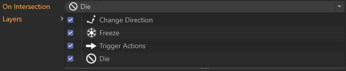
Layers list, with all available layer options included.
Trails
Section titled “Trails”Drag the xpTrail objects you want to avoid intersecting with into this list.
Normally you would drag the particle’s own xpTrail object into the list, but you can add trails from other emitters as well.
Actions
Section titled “Actions”Drag actions you want to be triggered, on detecting an intersection, into this list.
The actions will only be triggered if there is a Trigger Actions layer in the Layers list.
Add Action
Section titled “Add Action”Click this button to create a new action and add it to the Actions list.
When you click this button, if there is not already a Trigger Actions layer in the list, one will be created.
Groups Affected tab
Section titled “Groups Affected tab”Groups
Section titled “Groups”To specify the group, drag and drop the desired Group object into this field.
This setting is useful if you want to ensure that the spawned particles are, or are not, affected by xpBranch.
Mapping tab
Section titled “Mapping tab”The modifier’s settings can be mapped to particle data.
Use the dedicated manual page, below, for instructions on how this works.
Fields tab
Section titled “Fields tab”You can use the Fields options to control where xpBranch operates.
Copyright © 2026 INSYDIUM LTD. All rights reserved.