mtSplineFX
mtSplineFX takes in multiple start and end objects of polygonal, spline and xpEmitter types and creates a variety of spline connections between them.
Object tab
Section titled “Object tab”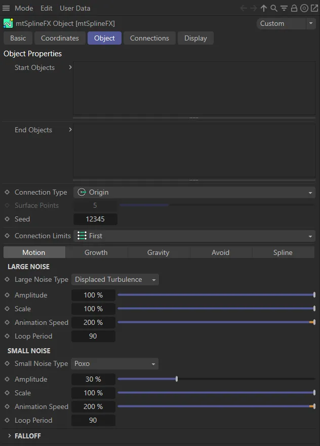
Object tab User Interface (UI) menu options.
In order for mtSplineFX to function, both a start and and object is required.
Start Objects, End Objects
Section titled “Start Objects, End Objects”Drag and drop your polygon, spline or xpEmitter into these lists to create the start and end points.
Connection Type
Section titled “Connection Type”Set as Origin, by default, select where on the object the start and end points will be generated.
The other options are: Points and Surface.
Origin
Section titled “Origin”A single connection made at the center of the object.
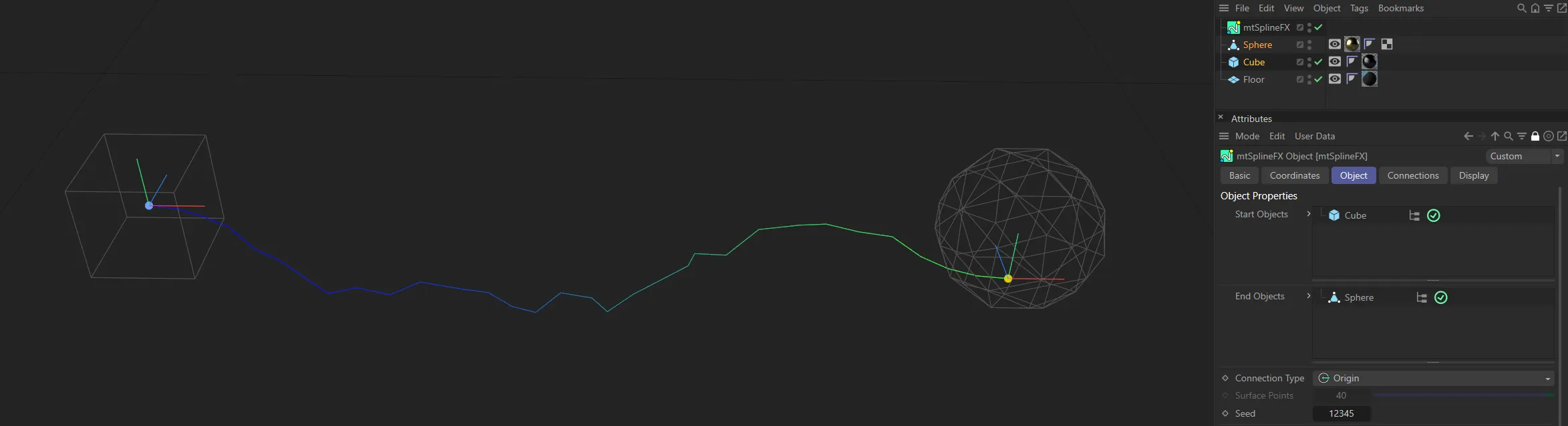
With a Connection Type of Origin, connections are generated from the axis points of the start end end objects (the Cube and the Sphere).
Points
Section titled “Points”Connections from the actual vertices of polygonal objects, real points of a spline or particles (if xpEmitter is selected as Start Objects or End Objects).
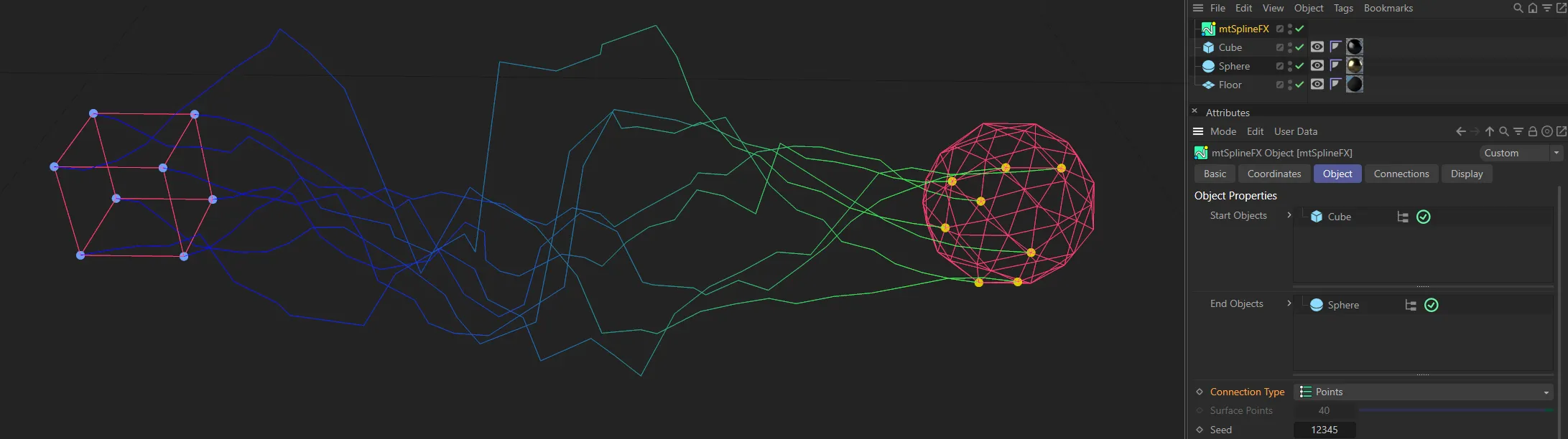
With a Connection Type of Points, connections are generated from the points, or vertices, of the start and end objects.
Surface
Section titled “Surface”Connection from a random surface of a polygonal object, at any distance along a spline or a particle (if xpEmitter is selected - as above).
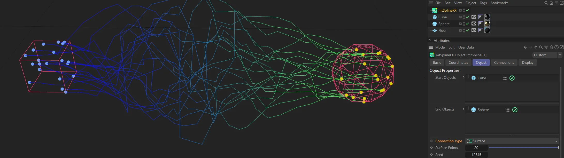
With the Connection Type of Surface, connections are generated from random points on the surfaces of the start and end objects..
Surface Points
Section titled “Surface Points”Only available in the Surface setting, this is the number of points to generate on each start and end object.
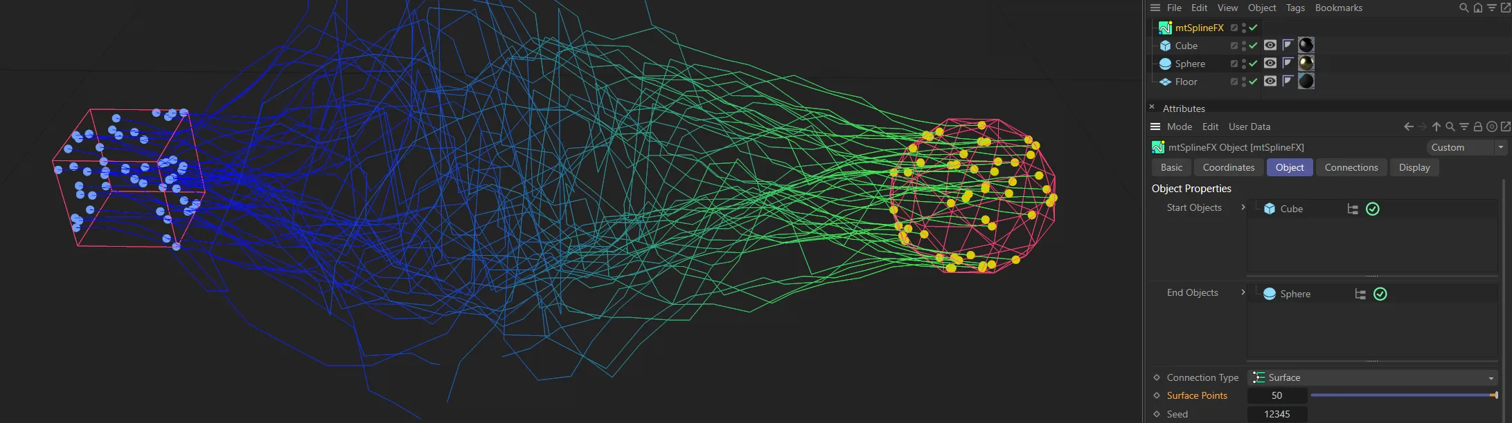
Here, in the Surface setting, the number of points generated come from the Surface Points value (of 50).
Gives a random connection, based on the settings above.
Connection Limits
Section titled “Connection Limits”Set as First, by default, this is the number of connections made, between start and end points.
Without a limit, a connection is made between each start point and every end point.
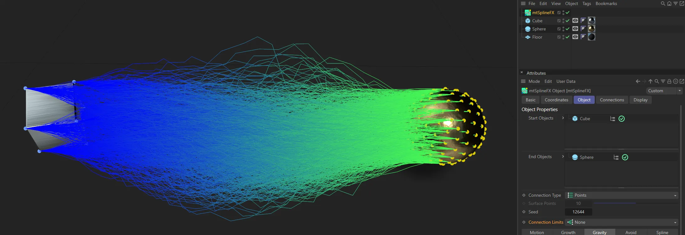
In this image, with a Connection Limits setting of None, there is a connection between each vertex of the Cube and every point of the Sphere.
With the Connection Limits setting changed to Facing, the connections are now only between each vertex of the Cube and every point of the Sphere that are facing each other.
A single connection is made between a start point and the first free end point.
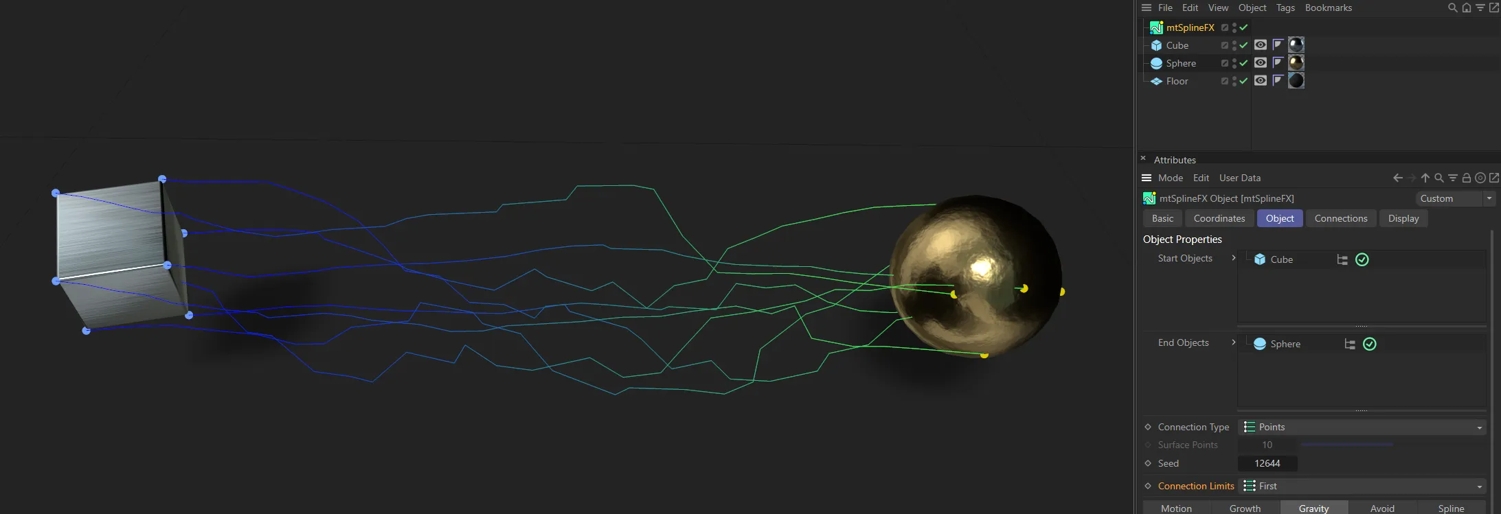
Here, with a Connection Limits setting of First, only one connection is made between a start point of the Cube and the first free end point of the Sphere.
Motion tab
Section titled “Motion tab”Motion effects spline animations.
A large and small noise modifier is applied to each spline line, with random distribution.
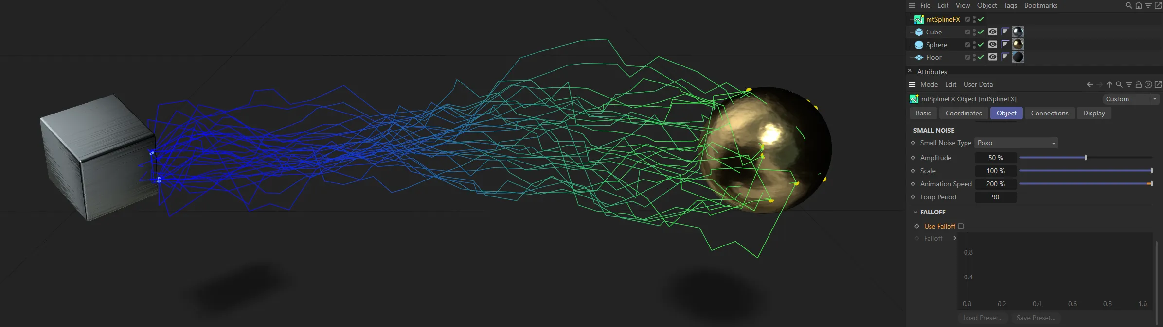
Large Noise Type, Small Noise Type
Section titled “Large Noise Type, Small Noise Type”These drop-down boxes contain all the standard Cinema 4D noise types.
Amplitude
Section titled “Amplitude”The amplitude of the noise waves.
This animation demonstrates the effect of the Amplitude parameter.
The size of the wave.
In this animation, an increase in the Scale from 5 to 150% shows how it affects the Amplitude setting.
Animation Speed
Section titled “Animation Speed”The speed at which the wave moves.
An increase in the Animation Speed is demonstrated in this animation.
Loop Period
Section titled “Loop Period”The number of frames reached before the animation repeats.
Falloff
Section titled “Falloff”Use Falloff
Section titled “Use Falloff”When ticked, falloff is enabled for both noises.
Use Falloff disabled.
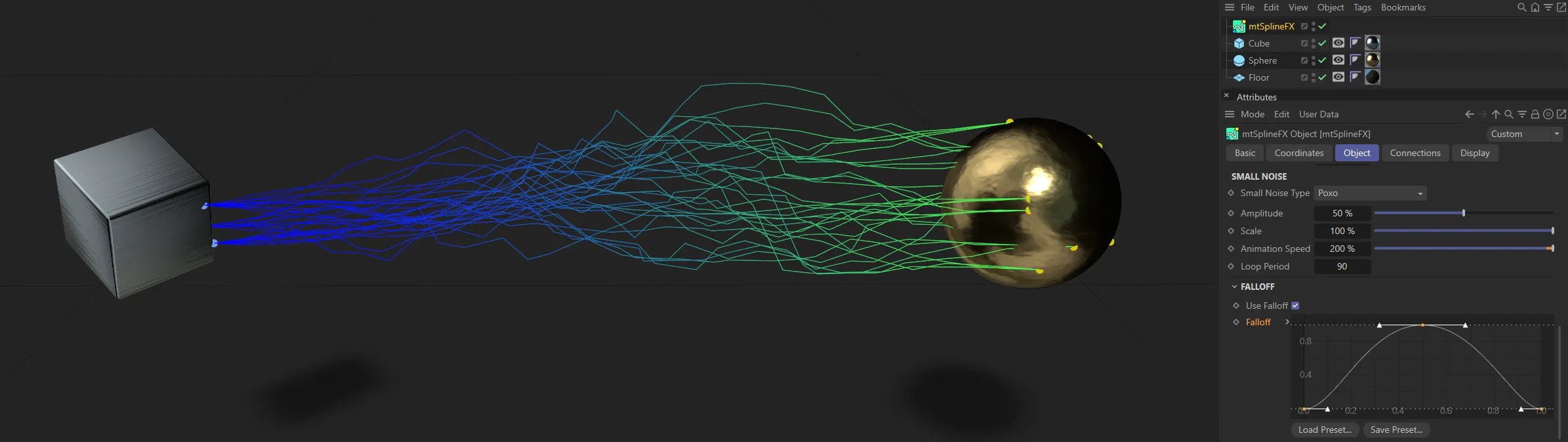
Use Falloff enabled, with the default Falloff setting.
Falloff
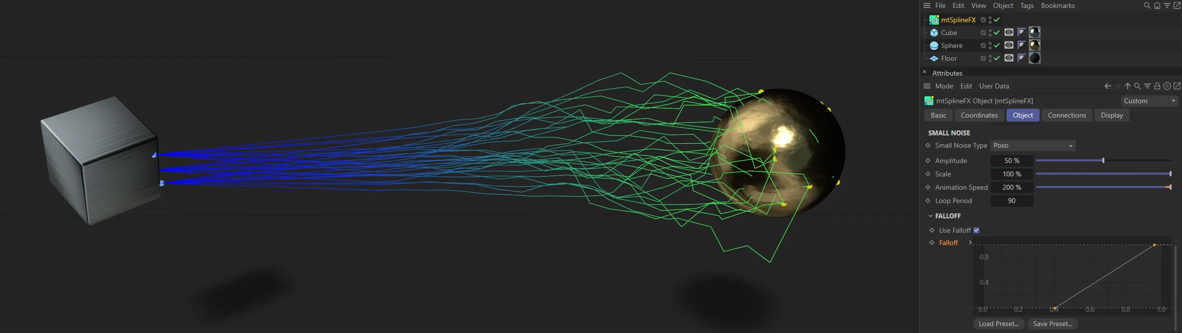
Section titled “Falloff”The falloff curve is used as a strength modifier to the noise, along the length of spline.
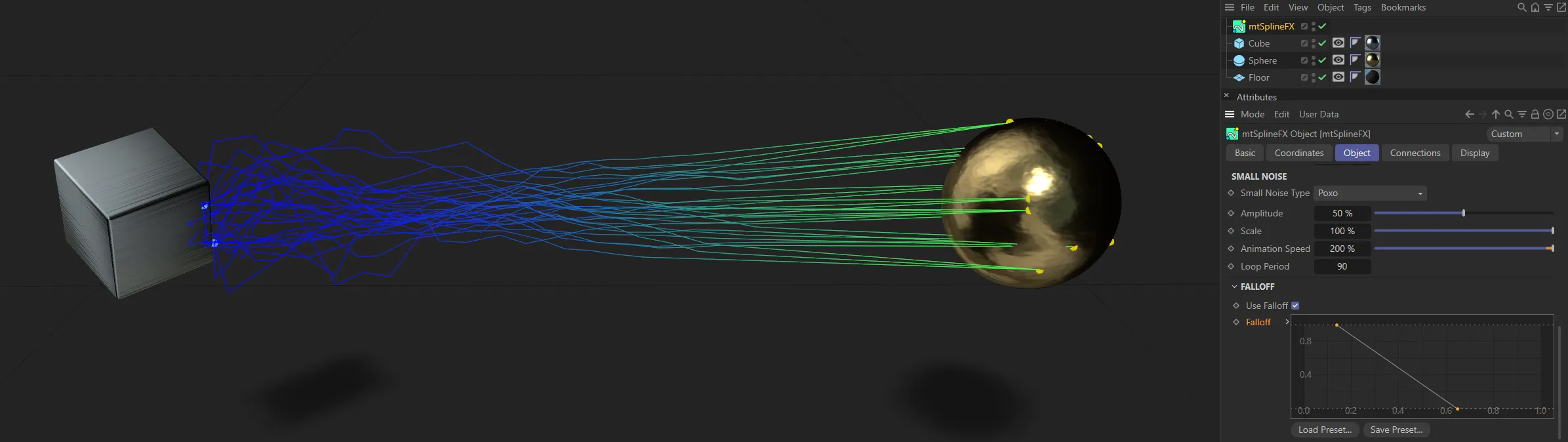
In these two images, the Falloff curve is driving the spline patterns.
Growth tab
Section titled “Growth tab”Growth Start
Section titled “Growth Start”Each primary spline will start at this percentage along its original path.
Animation of the Growth Start parameter.
Growth End
Section titled “Growth End”Each primary spline will end at this percentage along its original path.
Animation of the Growth End parameter.
Variation
Section titled “Variation”A random value will affect each splines growth values by this strength percentage.
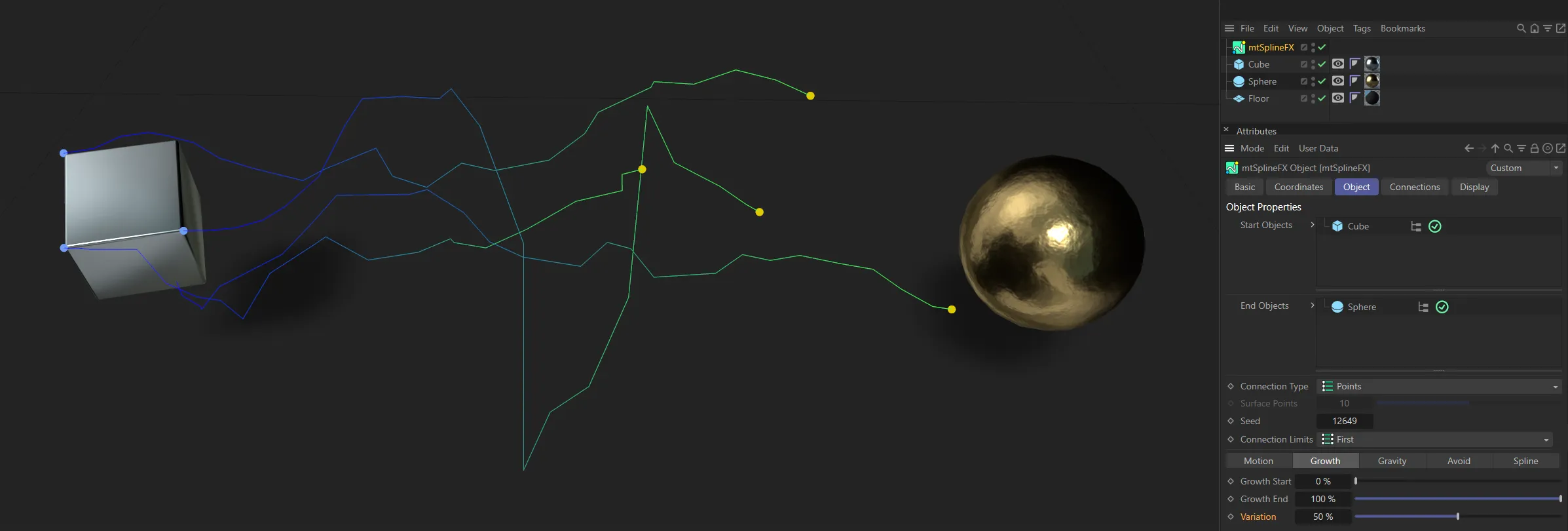
The Growth End setting is 100% here but, with the Variation at 50%, the splines are each at a different growth point.
Gravity tab
Section titled “Gravity tab”The gravity settings will ‘drop’ the center of each spline downwards, using a curve.
Strength
Section titled “Strength”The size of the drop.
Animation to demonstrate the effect of the Strength setting.
This animation demonstrates the effect of a negative gravity Strength setting, showing an inverted arcing of the splines.
Variation
Section titled “Variation”Variation applies a random modifier to the gravity strength of each spline.
This animation has the same Strength increase from 0 (zero) to 100%, but there is also a Variation setting of 100% here, giving different spline patterns.
This slider offsets the lowest point of the curve towards whichever end you choose.
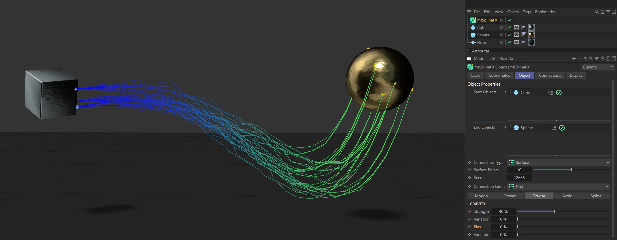
Bias value of 0 (zero) %.
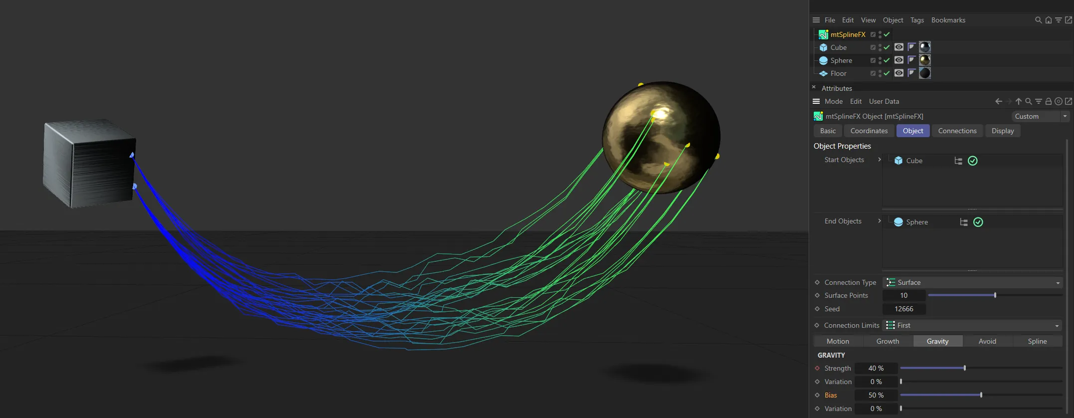
Here, the Bias is increased to 50%.
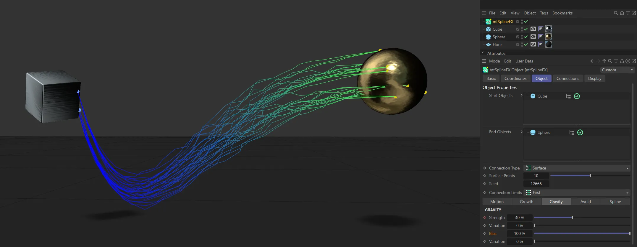
In this final image, the Bias is set at 100%.
Variation
Section titled “Variation”Changes the Bias value randomly between splines.
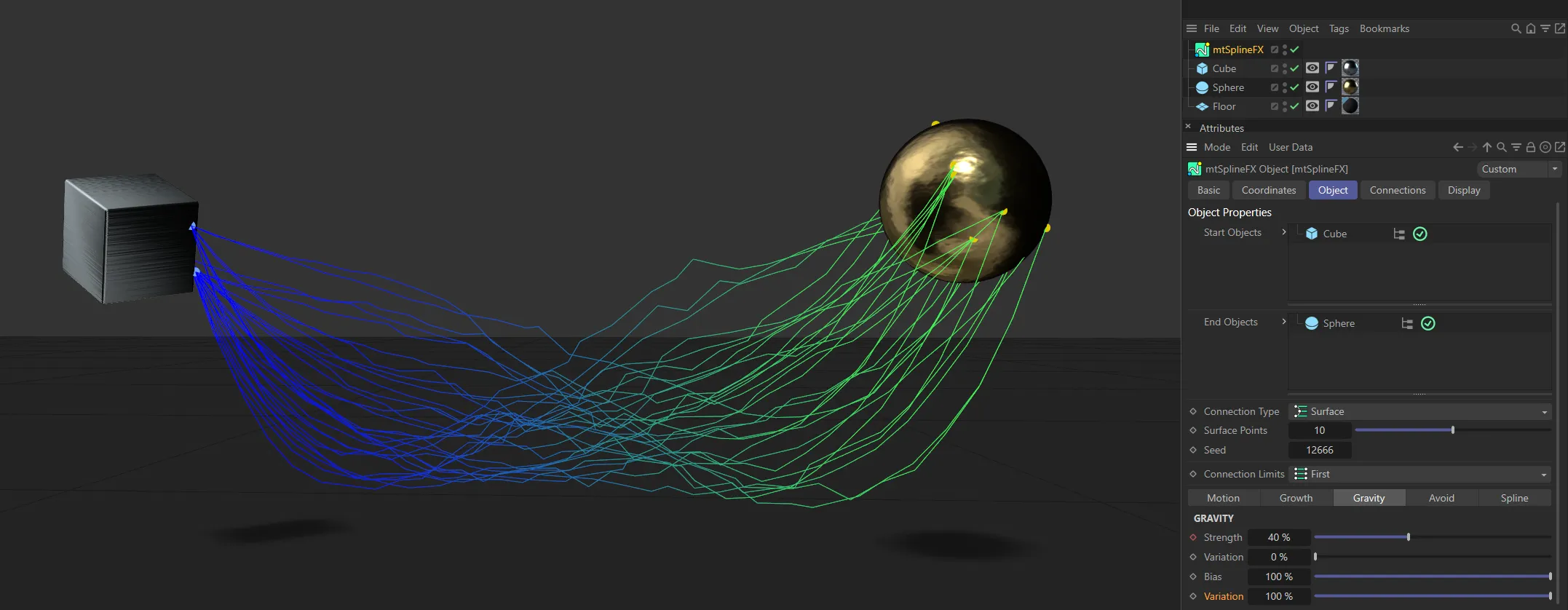
With the Bias set at 100%, the Variation value of 100% ensures there is a different pattern to each spline.
Tension
Section titled “Tension”Changes the shape of the curve, either to be more narrow or wider.
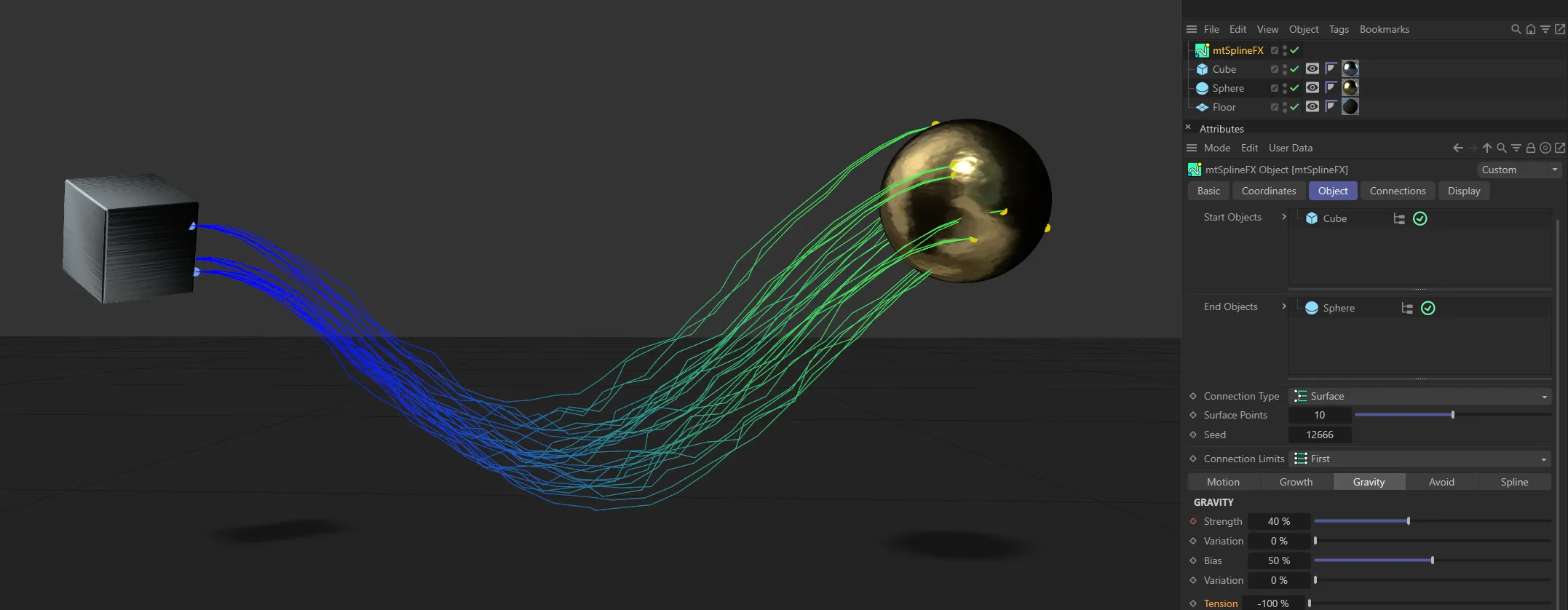
Tension set at -100%.
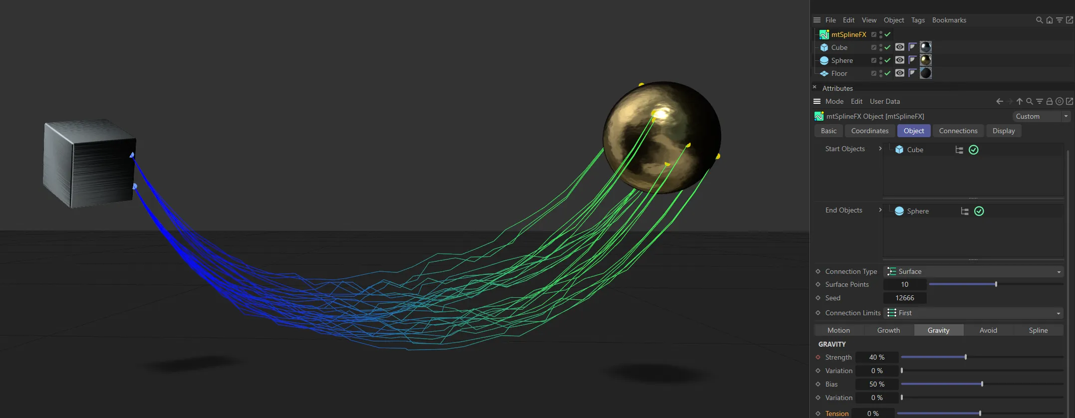
The Tension value is at 0 (zero) %, in this image.
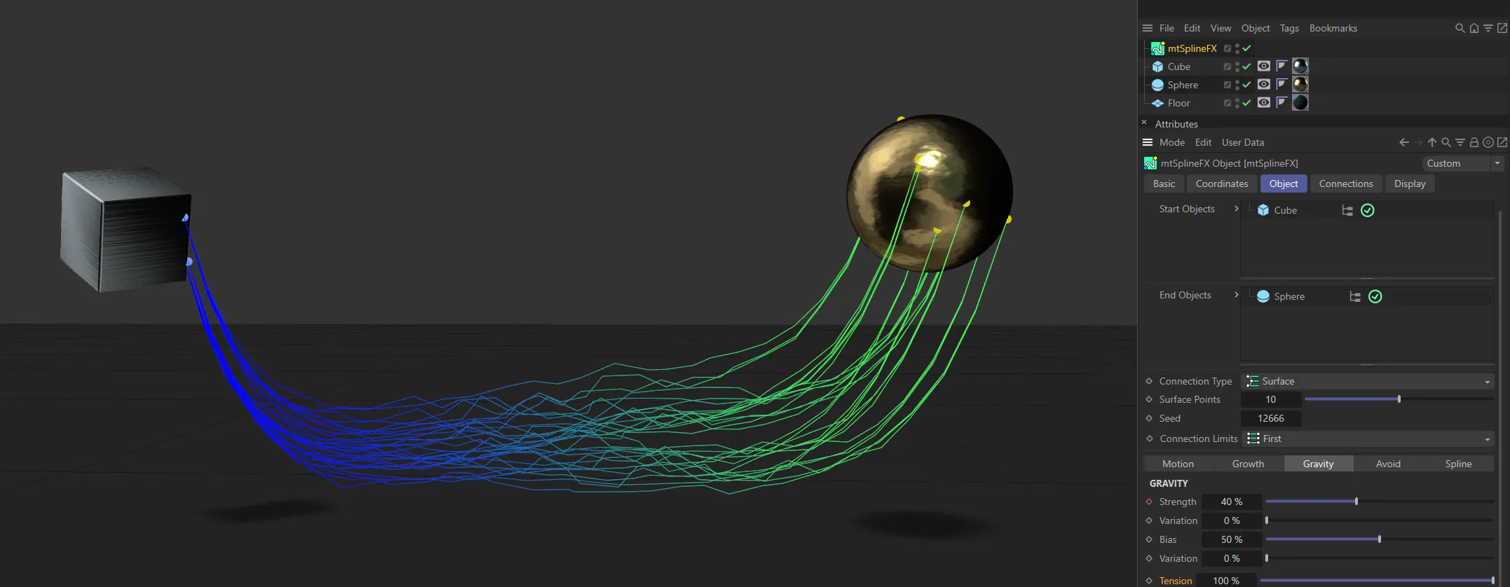
Tension raised to 100%.
Avoid tab
Section titled “Avoid tab”Avoid will modify each spline to arc around collider objects.
The resulting arc will be different if gravity is enabled.
Use Avoidance
Section titled “Use Avoidance”Check to enable the effect.
Include Forks
Section titled “Include Forks”Enabling this will ensure that the Fork splines (generated in the Connections tab) also avoid objects.
Weight
Section titled “Weight”A percentage value that affects the size of the arc.
This animation shows the effect of increasing the Weight setting.
A value which makes the arc shape more narrow.
In this animation, the Pinch value is being increased, narrowing the arc.
Avoid Objects
Section titled “Avoid Objects”Drag and drop any objects to be avoided into this list.
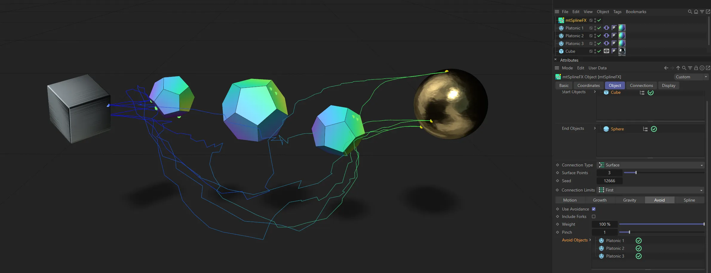
Three Platonic polygons have been dropped into the Avoid Objects list here, directing the splines to avoid them.
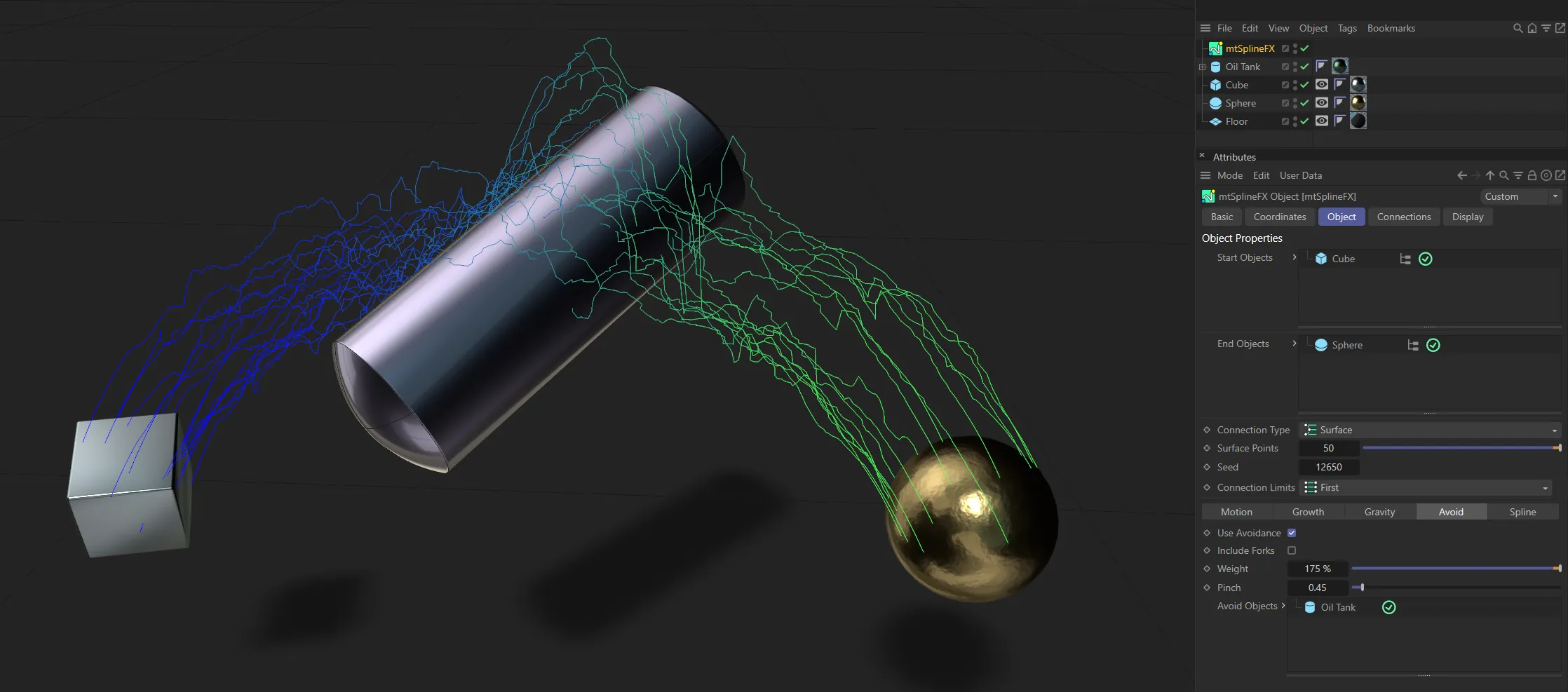
The splines are avoiding the Oil Tank, in the Avoid Objects list, working together with a negative gravity Strength value.
Spline tab
Section titled “Spline tab”The standard Cinema 4D options for each spline.
Set as Linear, by default, this changes how the spline shape is calculated.
The alternative options are: Akima, Bezier, B-Spline and Cubic.
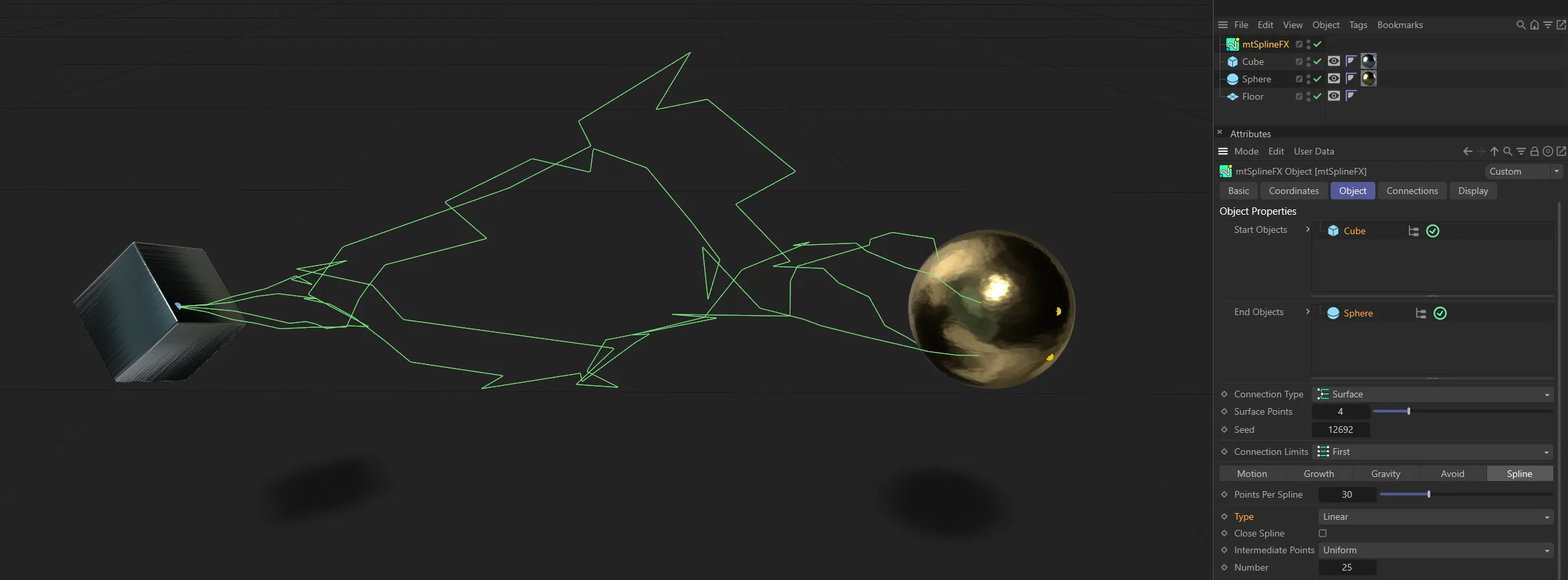
Linear spline Type setting.
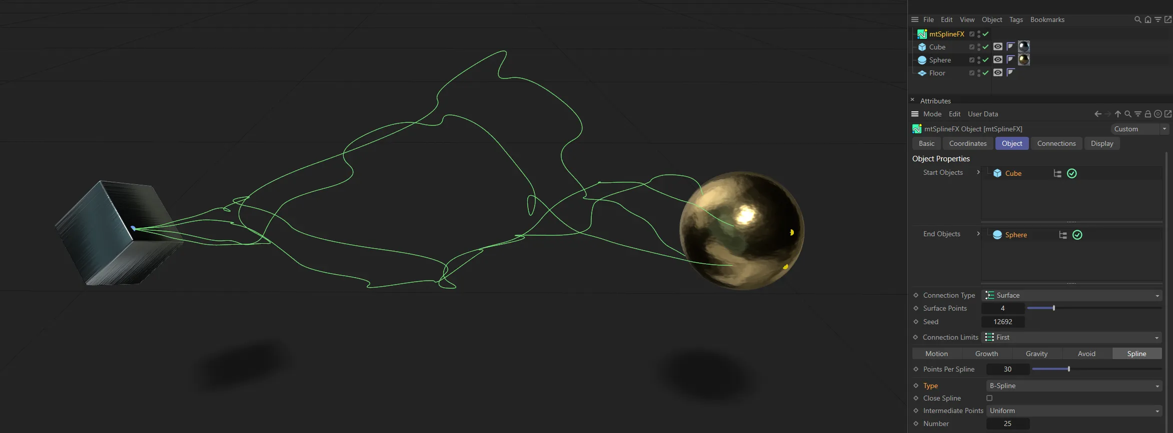
In this image, the Type setting is B-Spline.
Close Spline
Section titled “Close Spline”Enabling this will create a final section between the first and last points, closing the spline.
Intermediate Points
Section titled “Intermediate Points”Set as Natural, by default, these are the standard Cinema 4D options.
Alternatives are: None, Uniform, Adaptive and Subdivision.
Number, Angle, Max Length
Section titled “Number, Angle, Max Length”These options are relevant to different Type and Intermediate Point selections.
Connections tab
Section titled “Connections tab”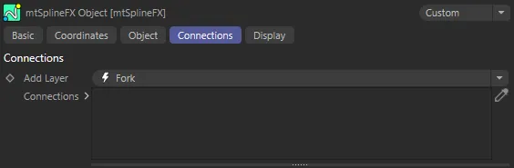
Connections tab menu options.
Connections expand the system by generating additional splines around the primary splines.
As the Connection list is hierarchical, a child node will generate its splines around a parent, rather than primary splines.
Add Layer
Section titled “Add Layer”A list-button, which lets you add in either a Fork or Nearest Distance layer connection node.
Fork connection
Section titled “Fork connection”A Fork connection will generate additional splines (forks) along either primary splines or along splines created by its parent node.
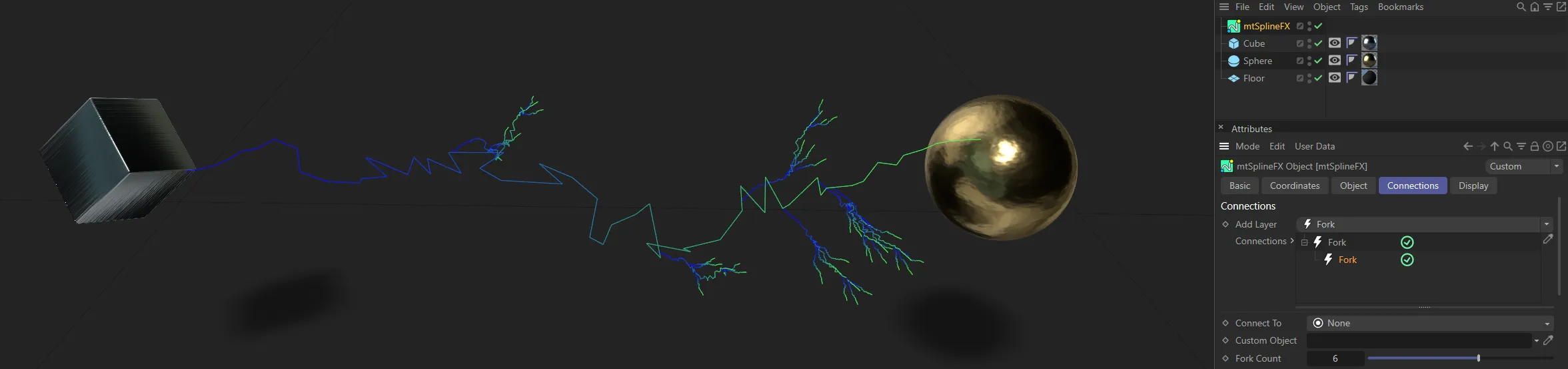
This images shows the Fork connection layer.
Nearest Distance connection
Section titled “Nearest Distance connection”The Nearest Distance connection type creates splines between generated points, or parent splines, within certain distance parameters.
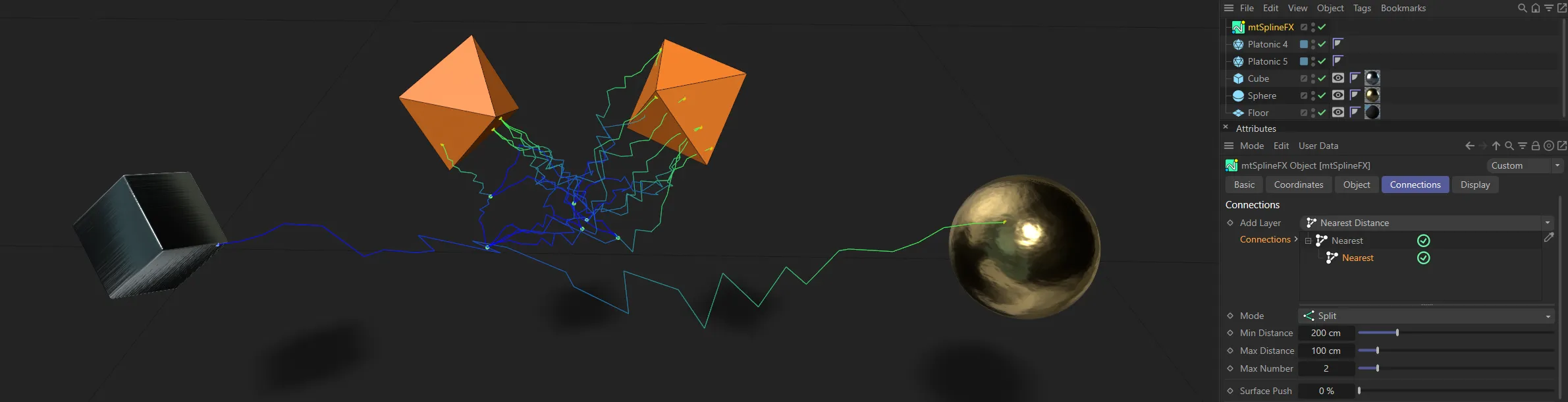
The Nearest Distance connection layer.
Connections
Section titled “Connections”The list of all current Connections.
This is a hierarchical list so order is important.
Fork connection settings
Section titled “Fork connection settings”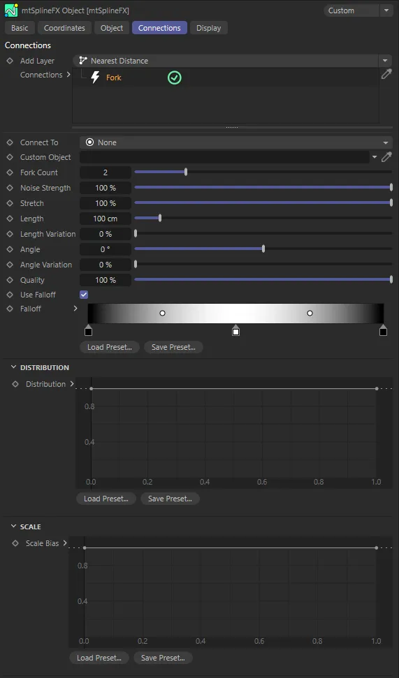
Fork connection menu settings.
Connect To
Section titled “Connect To”Set as None, by default, the user can choose the direction of the forks.
The other settings are: Start Objects, End Objects and Custom Object.
Each new Fork spline will point away from the center of the spline.
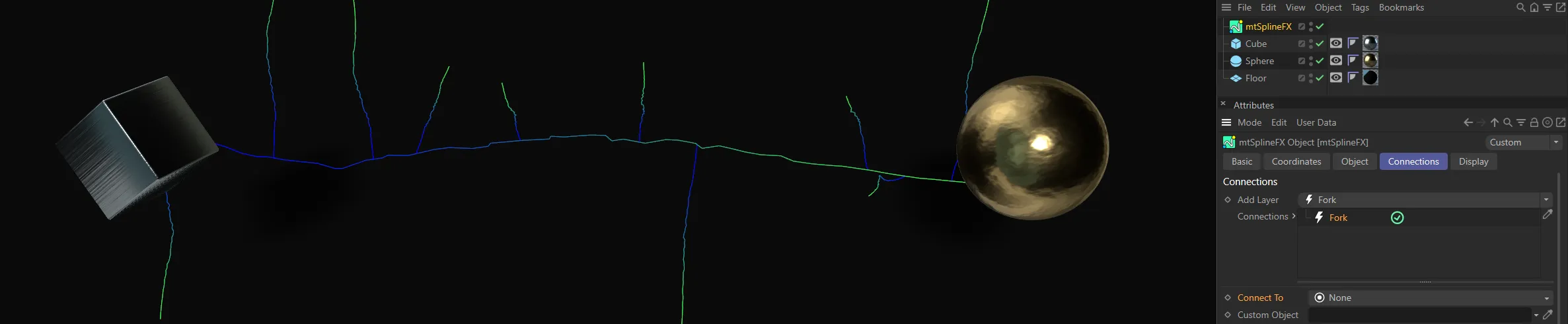
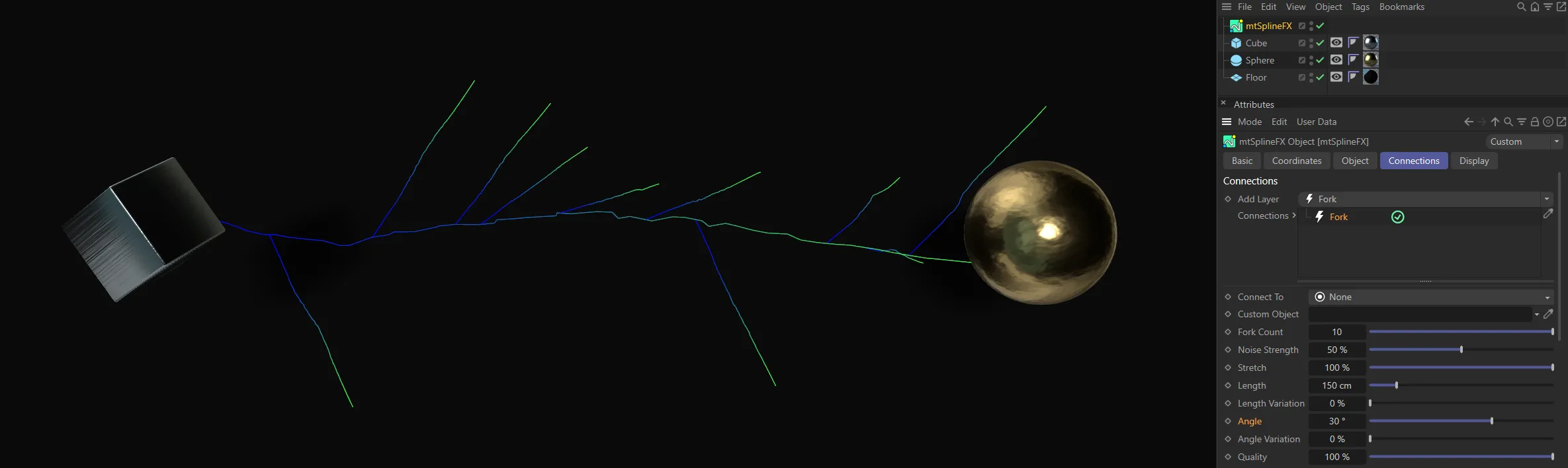
Here, the Connect To setting is None, with Fork splines pointing away from the spline.
Start Objects
Section titled “Start Objects”Forks will face towards a random surface of a random start object.
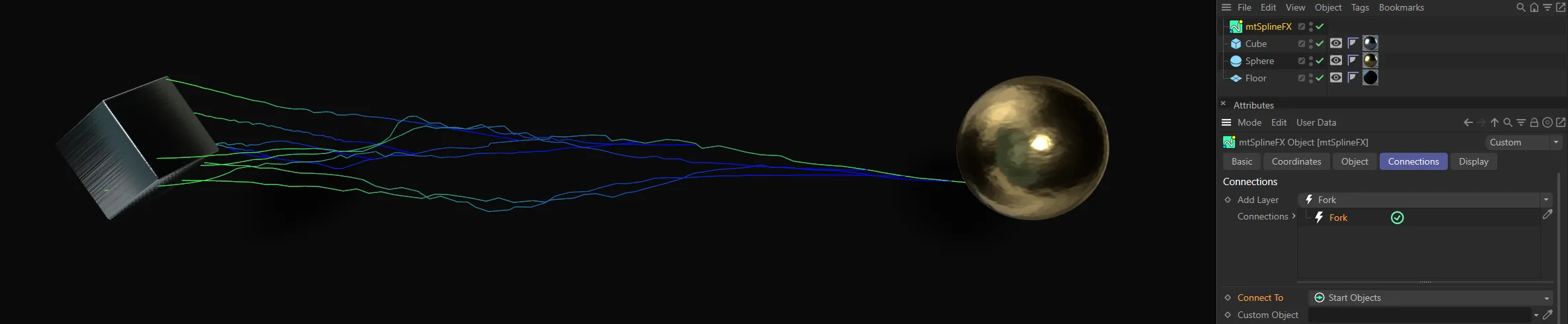
In this image, the Connect To setting is Start Objects.
End Objects
Section titled “End Objects”Similar to above, but with end objects.
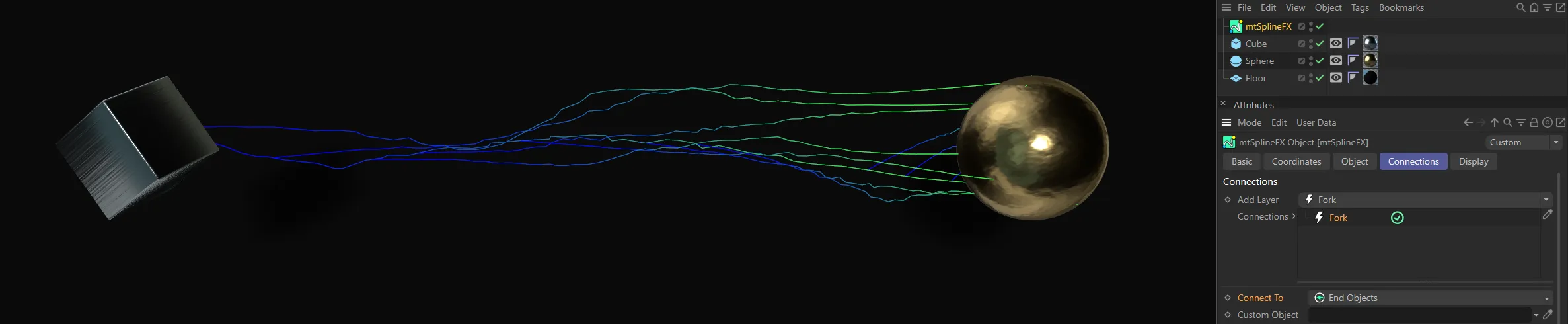
The End Objects setting shows almost a mirrored version of the above.
Custom Object
Section titled “Custom Object”Forks will face towards a random surface on a user-chosen object.
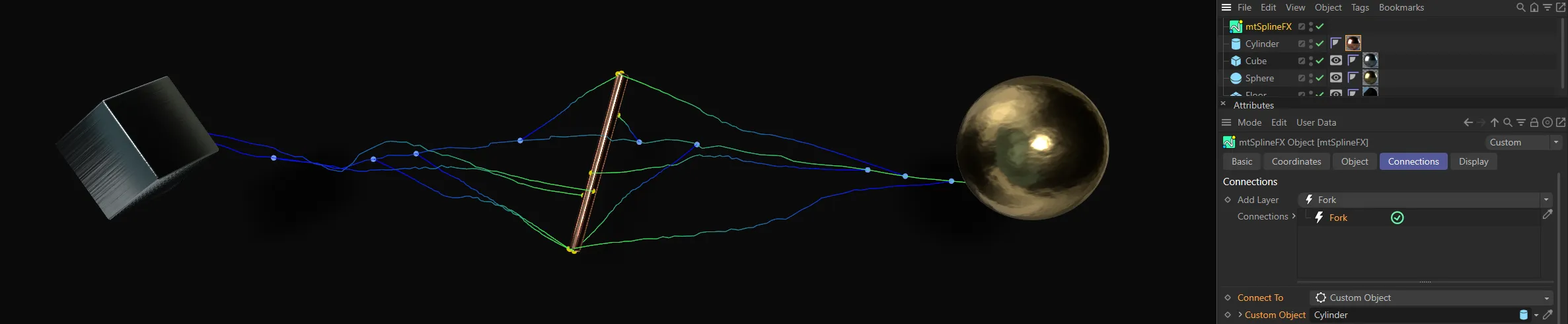
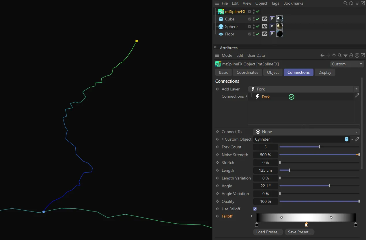
In the Custom Object setting, with the Fork connection layers facing the Cylinder, which is dropped in the Custom Object field.
Custom Object
Section titled “Custom Object”This field accepts different objects for forks to point towards, if Connect To is set as Custom Object.
Fork Count
Section titled “Fork Count”How many forks are generated per spline.
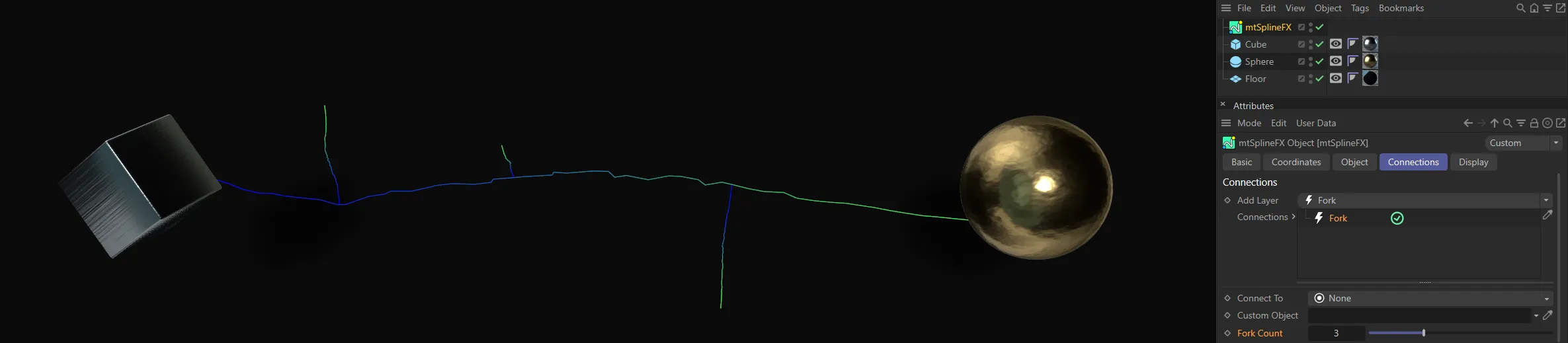
A Fork Count setting of 3.
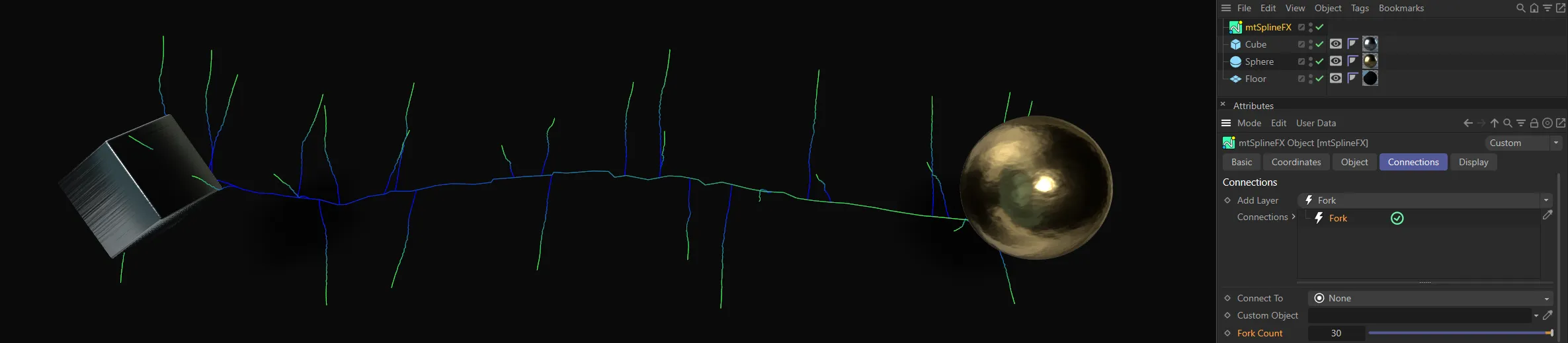
Fork Count increased to 30.
Noise Strength
Section titled “Noise Strength”Forks will inherit the main noise value, which can be toned down by decreasing the Noise Strength value.
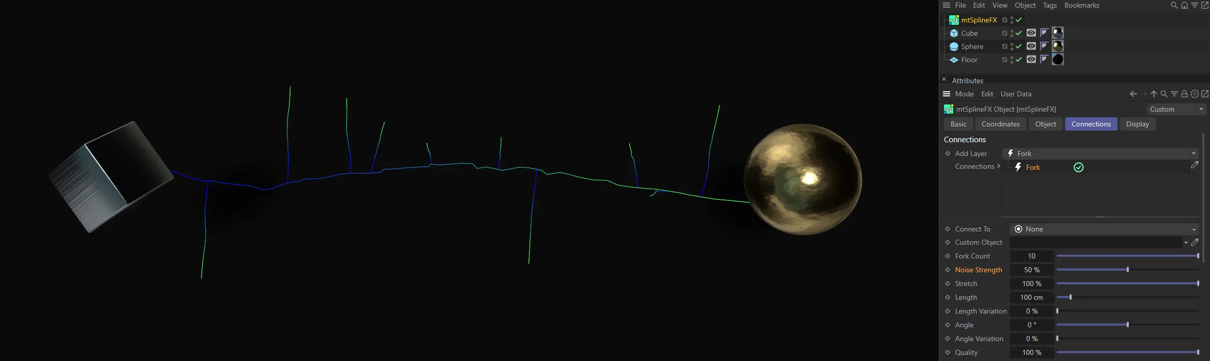
In this image, the Noise Strength is at 50%.

Here, the Noise Strength is increased to 500%.
Stretch
Section titled “Stretch”If Connect To is not set as None, the length of fork is set equal to the distance from the start point, to the random point on the object surface.
The Stretch value affects this size as a percent.
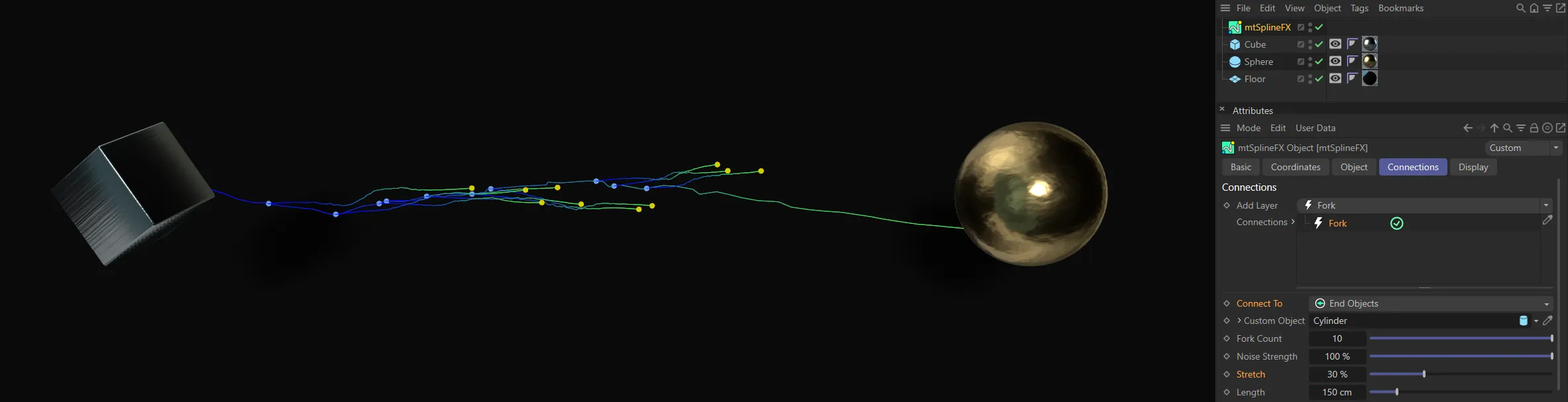
Stretch value set at 30%.
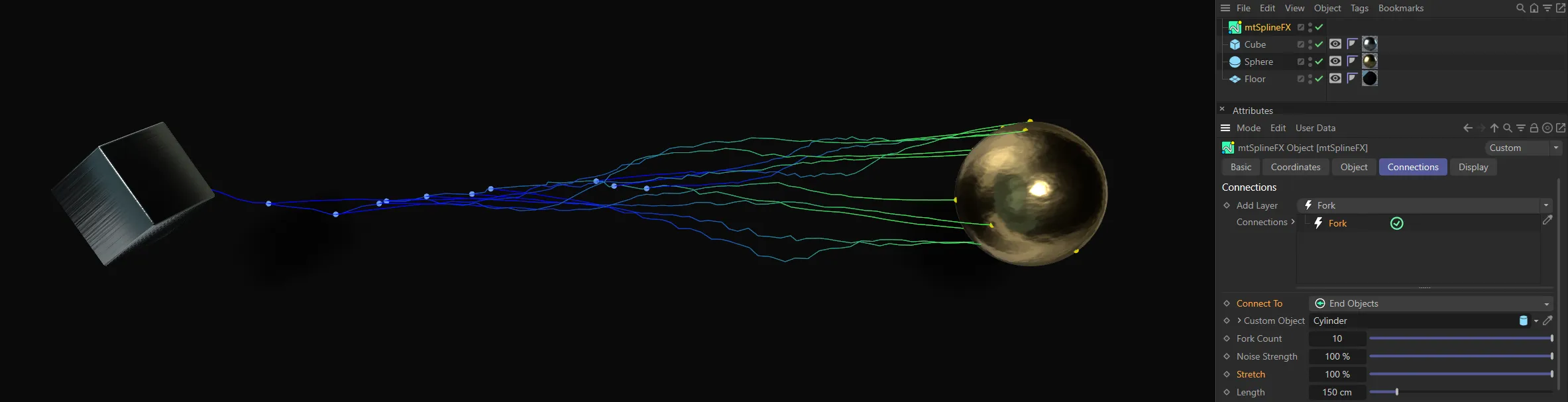
Here, the Stretch value has been raised to 100%.
Length
Section titled “Length”If Connect To is set as None, each fork is given this arbitrary distance as a length.
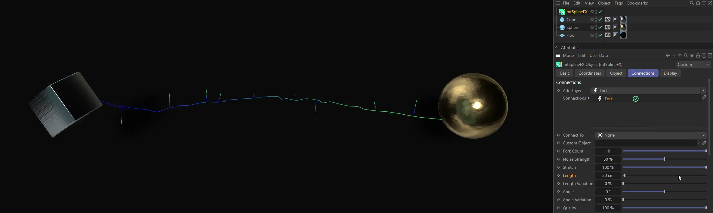
The Length setting is 30cm, in this image.

With the Length increased to 150cm, the Fork connections are longer.
Length Variation
Section titled “Length Variation”Varies the length between each fork.
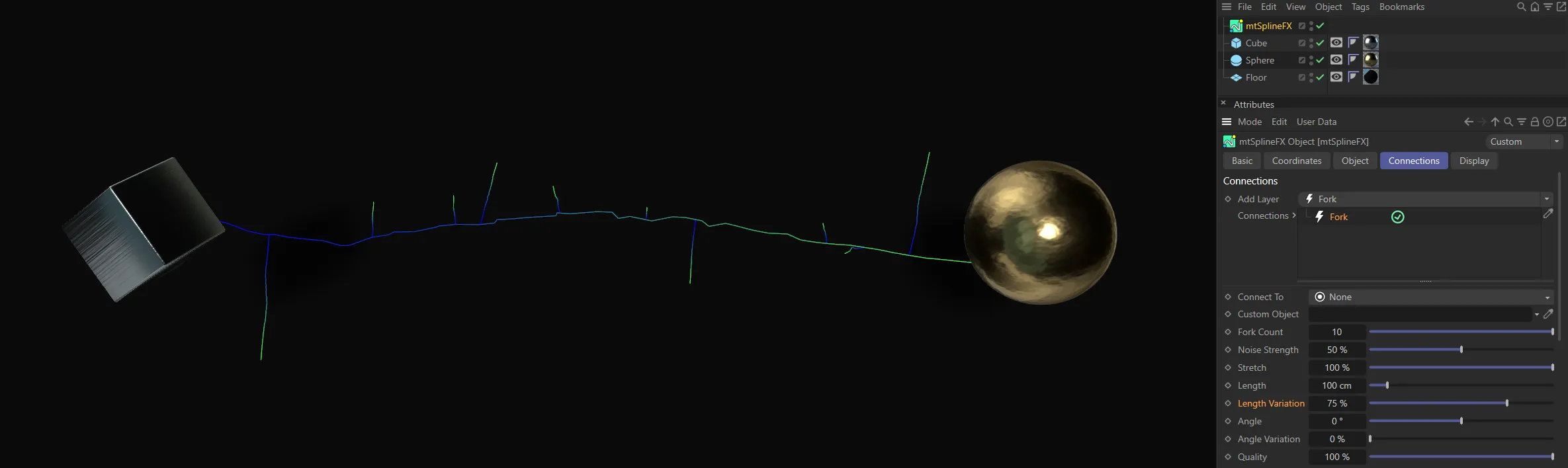
A Length Variation of 75%, giving a large variety of Fork connections.
Forks can have their initial direction offset by this amount.
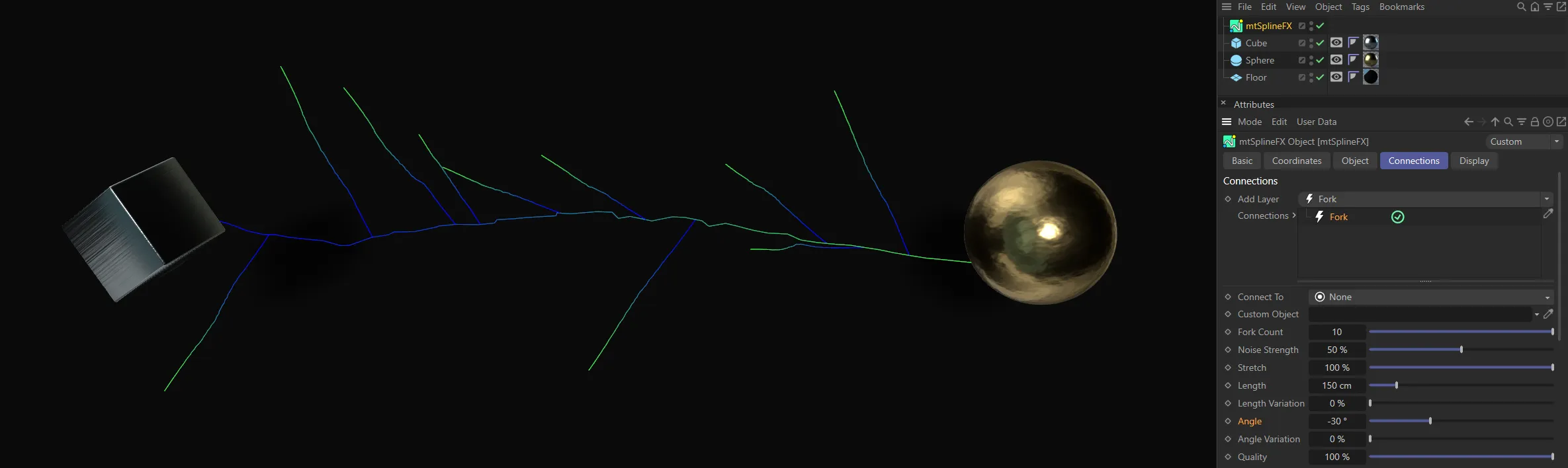
Angle setting of (negative) -30 degrees.
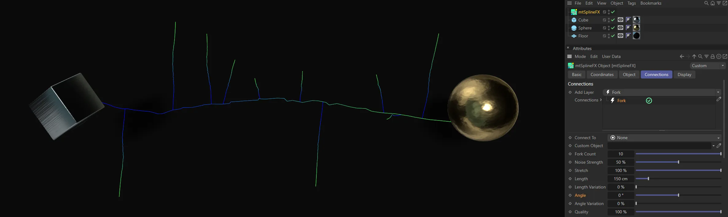
With the Angle setting at 0 (zero) degrees, the Fork connections are at their default.
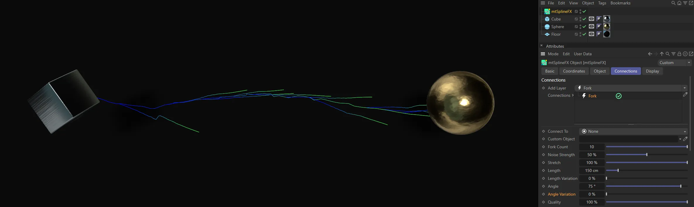
In this image, the Angle is raised to 30 degrees.
Angle Variation
Section titled “Angle Variation”Varies the angle of each fork.
Here, there is no Angle Variation, set at 0 (zero) %.
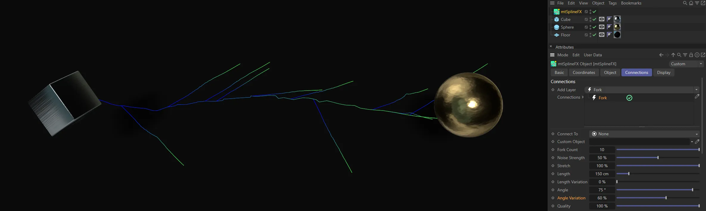
Angle Variation raised to 60%.
Quality
Section titled “Quality”Forks will inherit the main Points Per Spline count (Object tab), but this can be reduced by lowering the quality.
Use Falloff
Section titled “Use Falloff”Check the box to enable the Falloff settings.
Falloff
Section titled “Falloff”With Use Falloff enabled, the strength of noise along the fork will be adjusted by this gradient value.
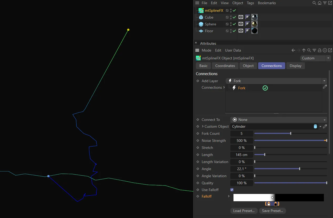
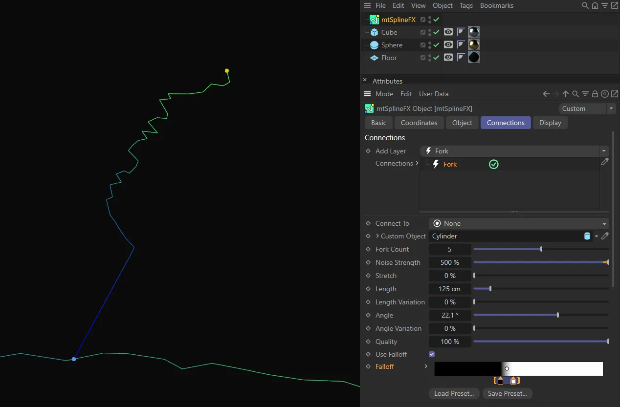
Use Falloff is enabled in all three of these images, with the differing noise settings being driven from the Falloff gradients shown.
Distribution
Section titled “Distribution”Distribution
Section titled “Distribution”Manipulate this curve to change the probability of forks being generated at each point along the line.

The default Distribution setting.
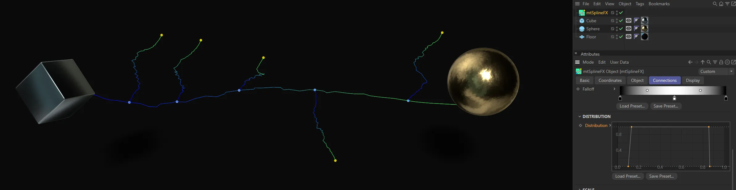
The Distribution spline setting is driving the generation of Fork connections on this spline.

A slightly amended setting gives this look.
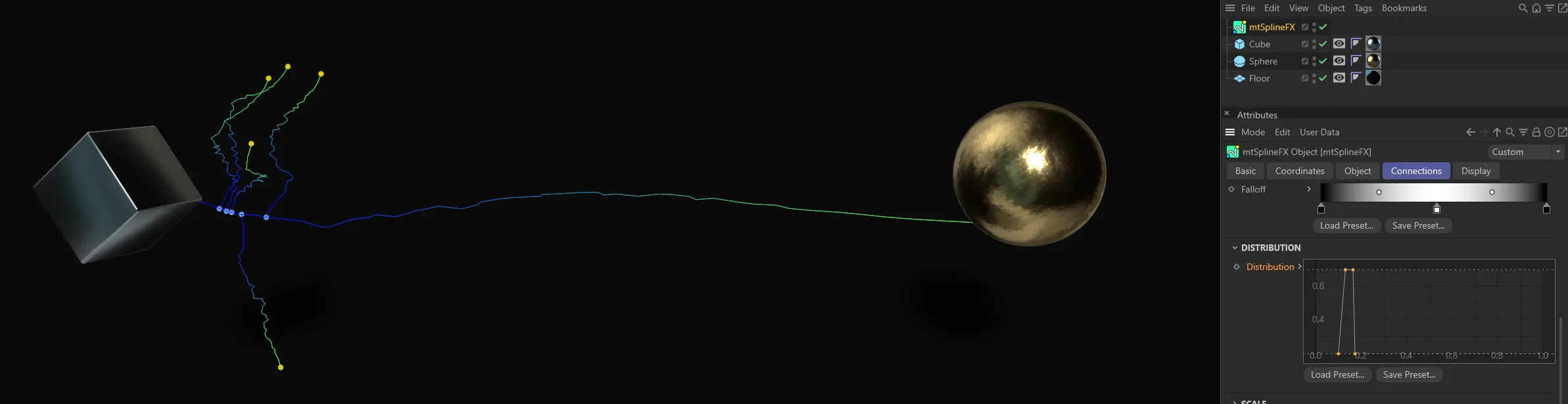
This setting ensures the Fork connections are restricted to the start of the spline.
Scale Bias
Section titled “Scale Bias”Similar to Distribution, above, this affects the scale of the forks.
An increasing linear Scale Bias spline setting results in smaller forks at the start with a linear increase in scale to the larger forks at the end.
With the Scale Bias at full strength, all forks are at true to the Length value.

This custom user spline emphasises the scale of the second to last fork and reduces the scale of the other forks.

This downward linear setting is the opposite of the top image and results in larger forks at the start with a linear decrease in scale towards the end.
Nearest Distance connection settings
Section titled “Nearest Distance connection settings”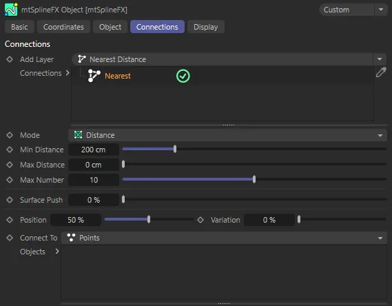
Nearest Distance connection menu settings.
Set as Distance, by default.
The alternative setting is Split
A spline will be generated from a point along a parent spline, to a random point on an object chosen below.
Distance
Section titled “Distance”A spline will be created between points generated on the surface of each object.
Min Distance
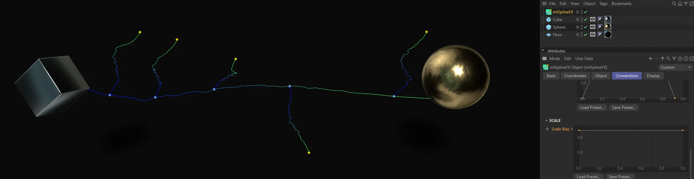
Section titled “Min Distance”Points must be closer than this to be connected.
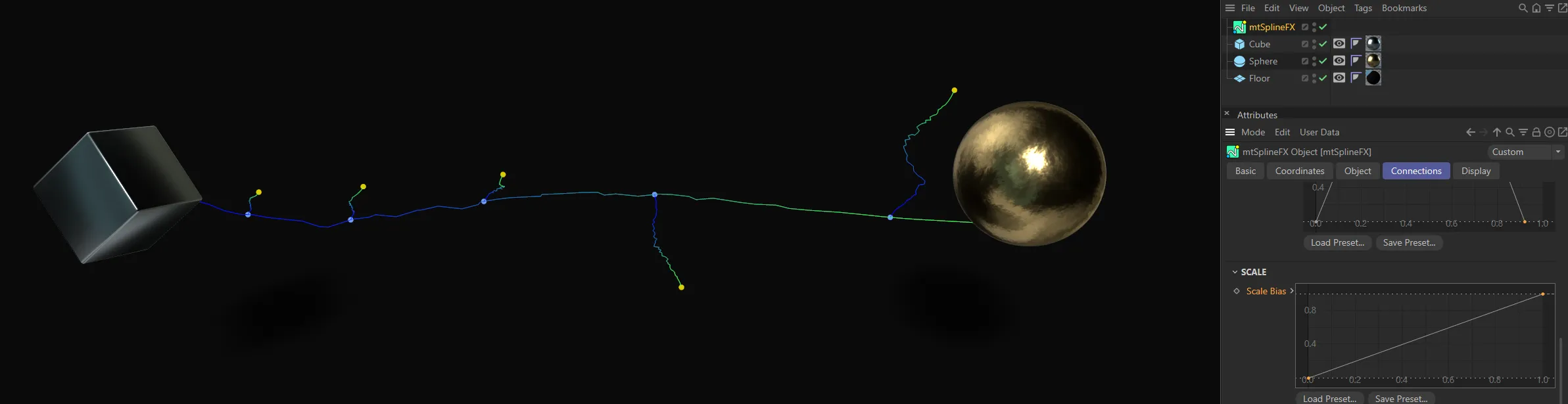
Only points within the 300cm Min Distance value are connected.

With Min Distance lowered to 200cm, less points are close enough to be connected.
Max Distance
Section titled “Max Distance”Points must be further away than this to be connected.
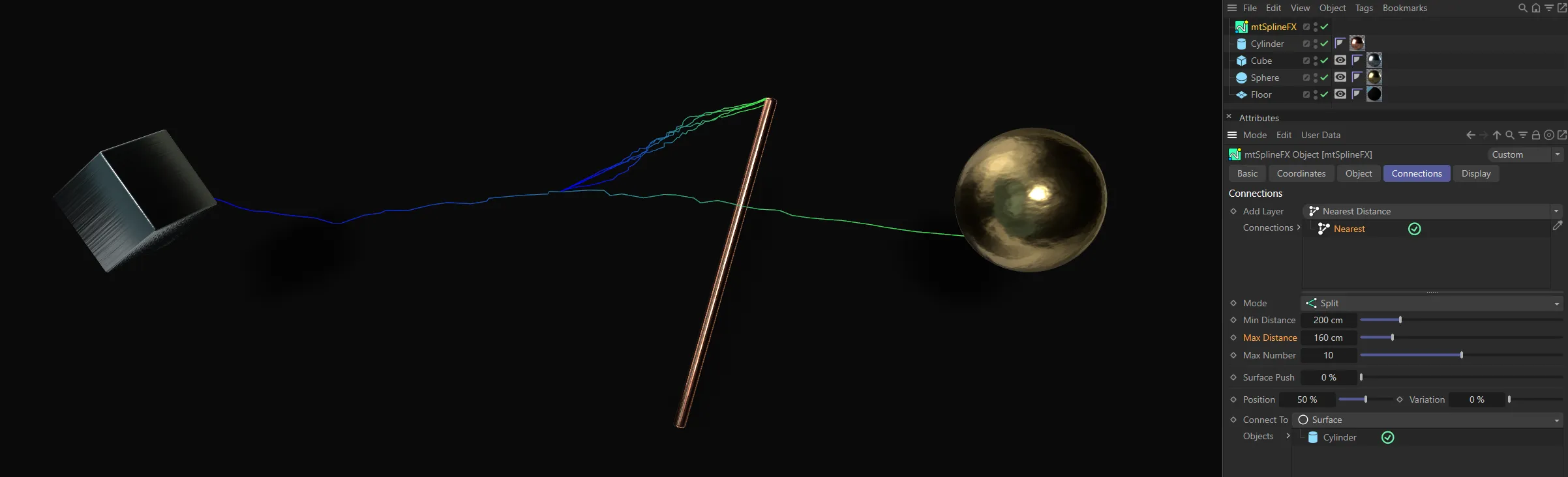
Conversely, only points further away than the Max Distance value of 160cm are connected, here.
Max Number
Section titled “Max Number”Limit the number of connections per each point.
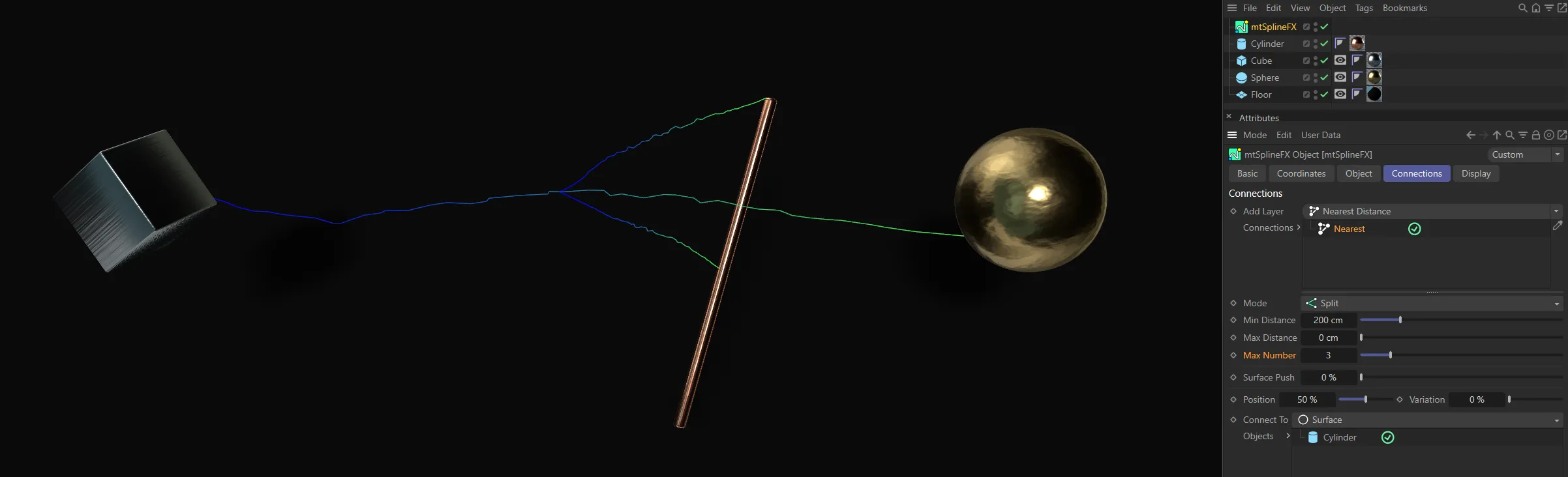
The Max Number value of 3 means only 3 connections are made per point.
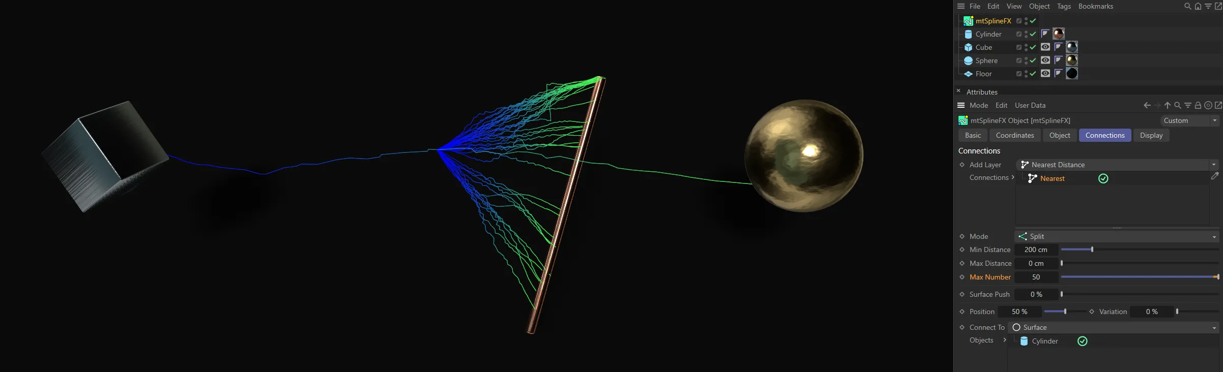
In this image, the Max Number value has been raised to 50, giving 50 connections per point.
Surface Push
Section titled “Surface Push”If the Mode is set to Distance, this value will shift the new spline away from the surface of the object.
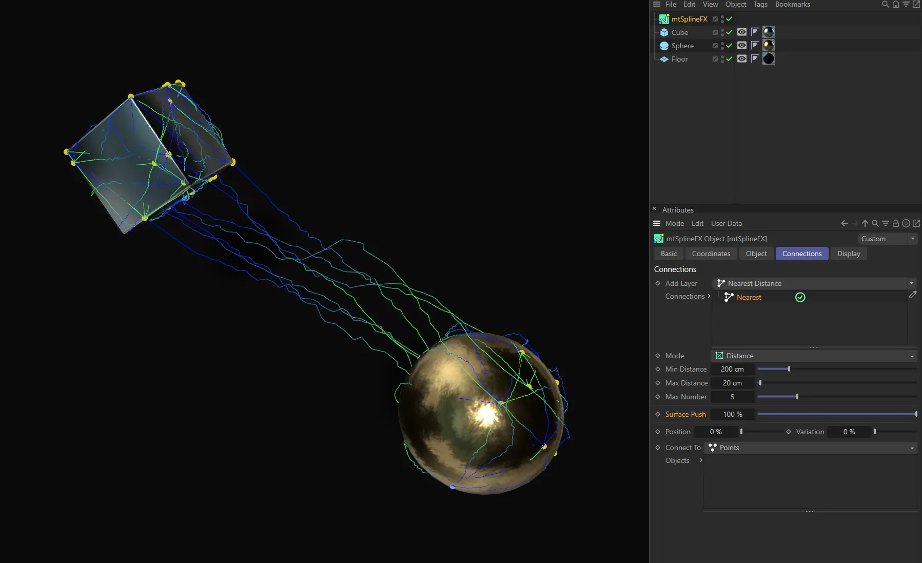
This first image has Surface Push set at 100%.
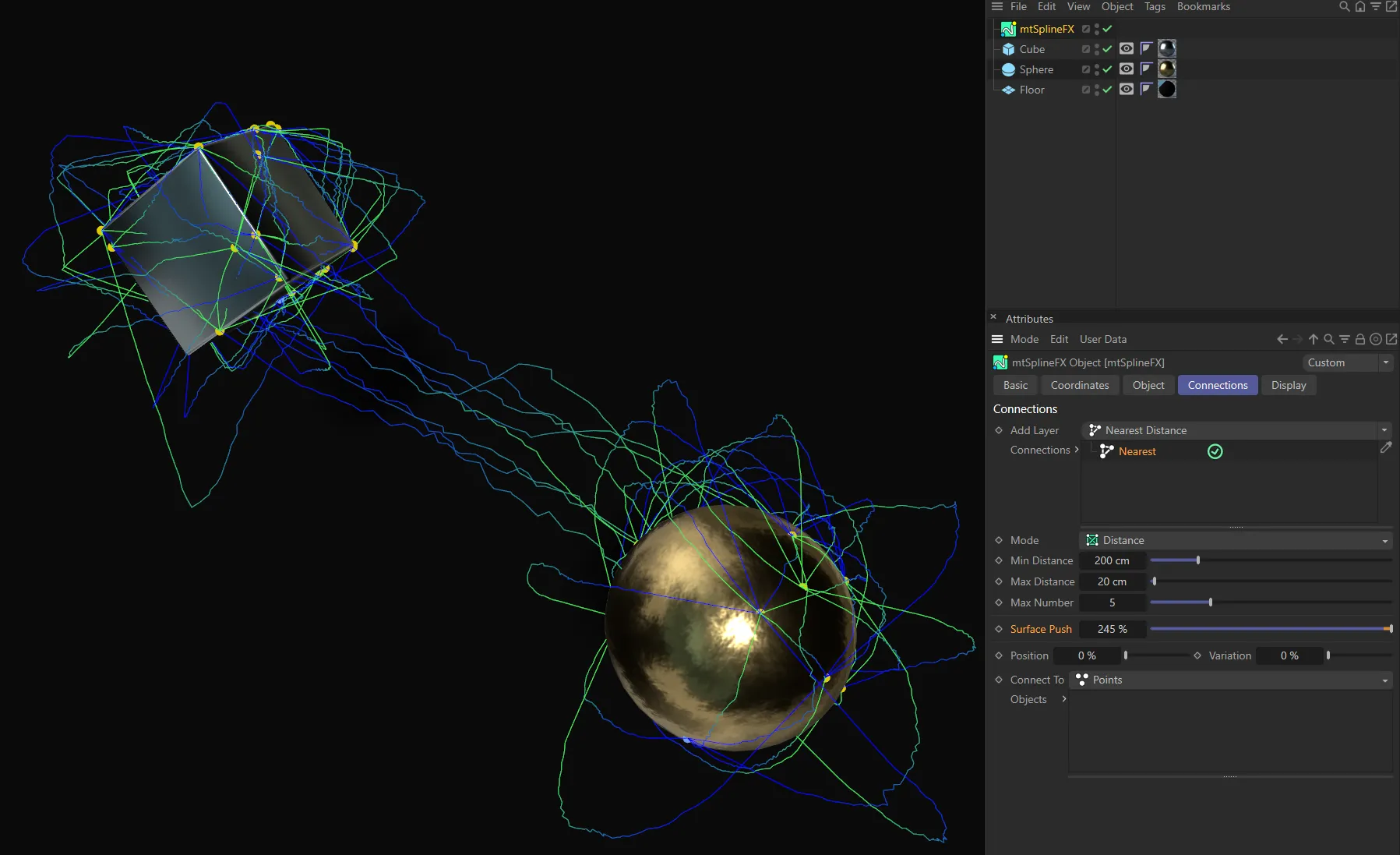
With Surface Push raised to 245% the splines are pushed away from the surface of the objects.
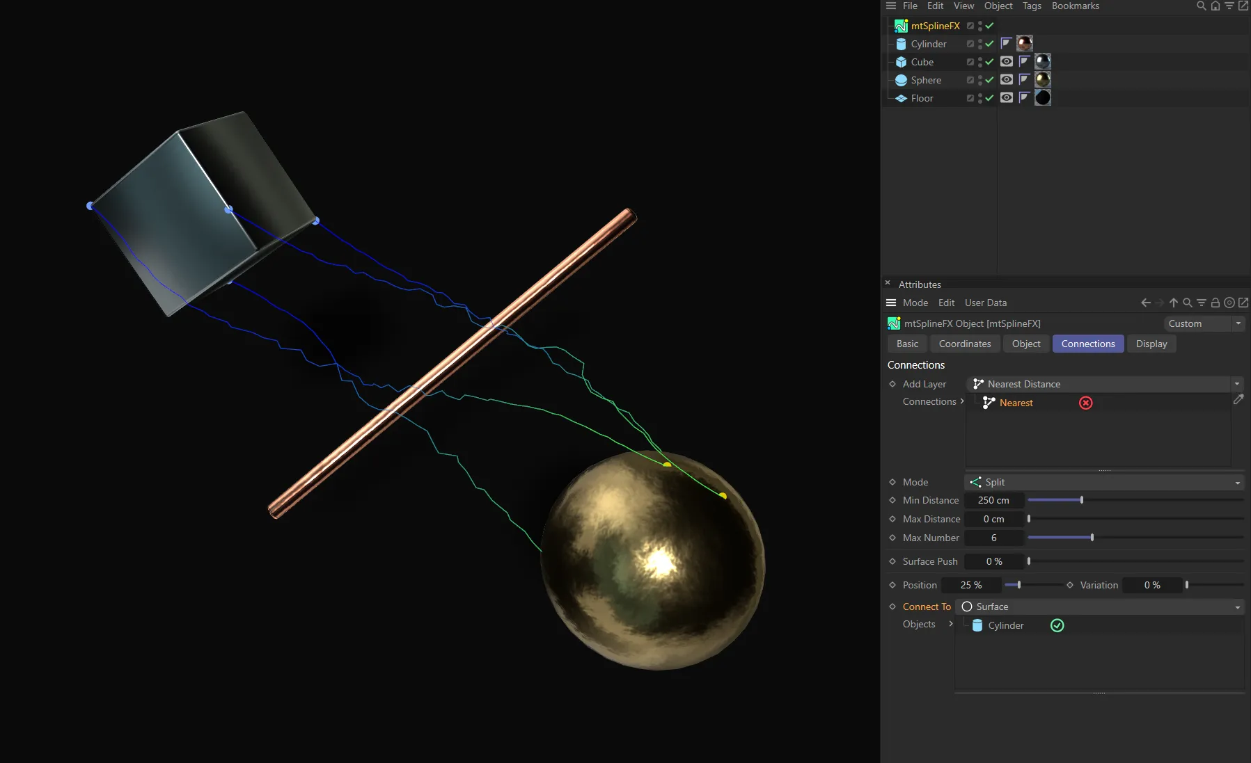
Position
Section titled “Position”If the Mode is set to Connections, shift the connection point along the parent spline by this value.
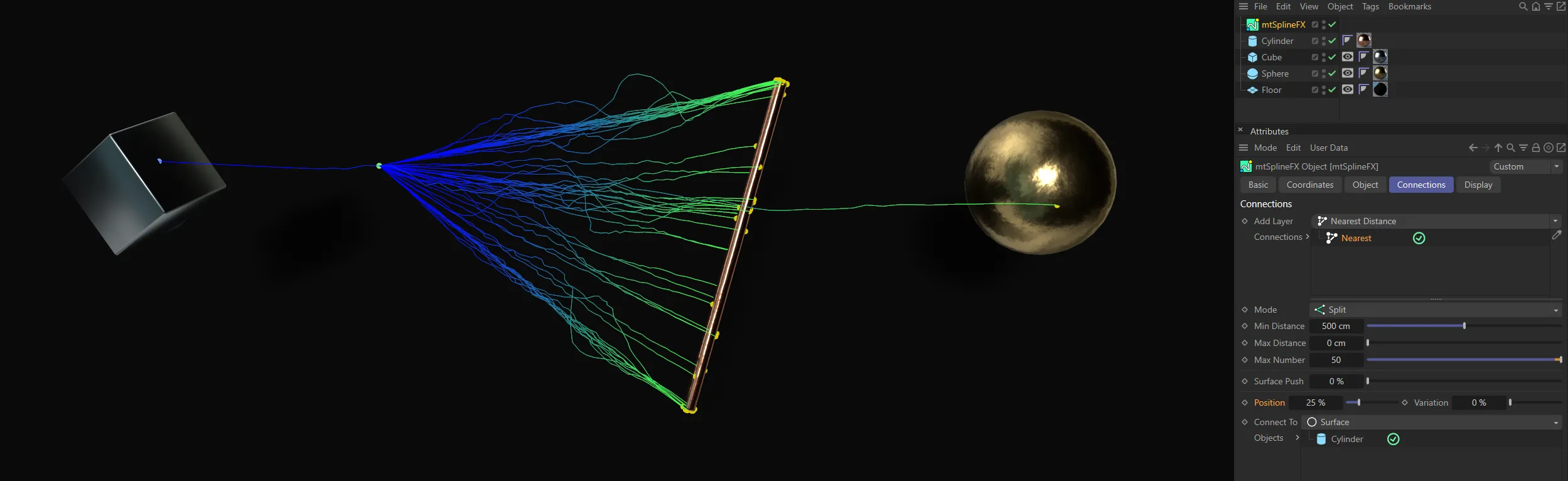
The Position value of 25% moves the connection point to a quarter of the way along the parent spline.
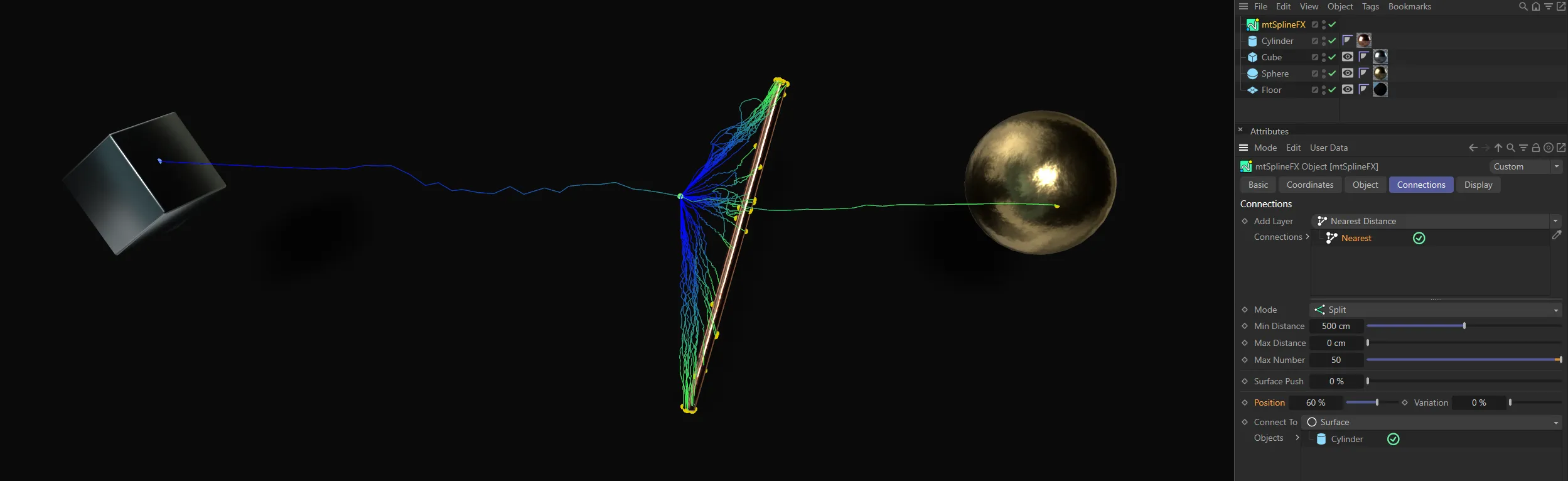
With the Position raised to 60%, the connection point is moved further along.
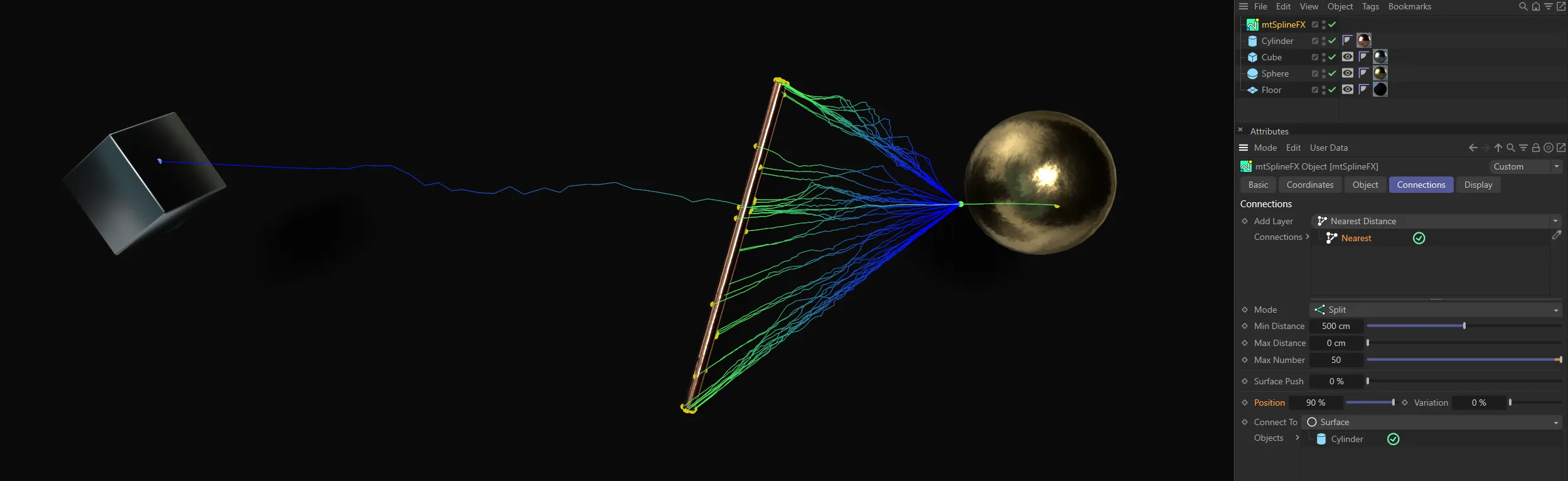
And, finally, Position is set at 90% here, putting the connection point almost at the end of the parent spline.
Variation
Section titled “Variation”Randomly adjust the starting position of each spline by this value.
Variation at 0 (zero) %, meaning there is no variation to the starting points.
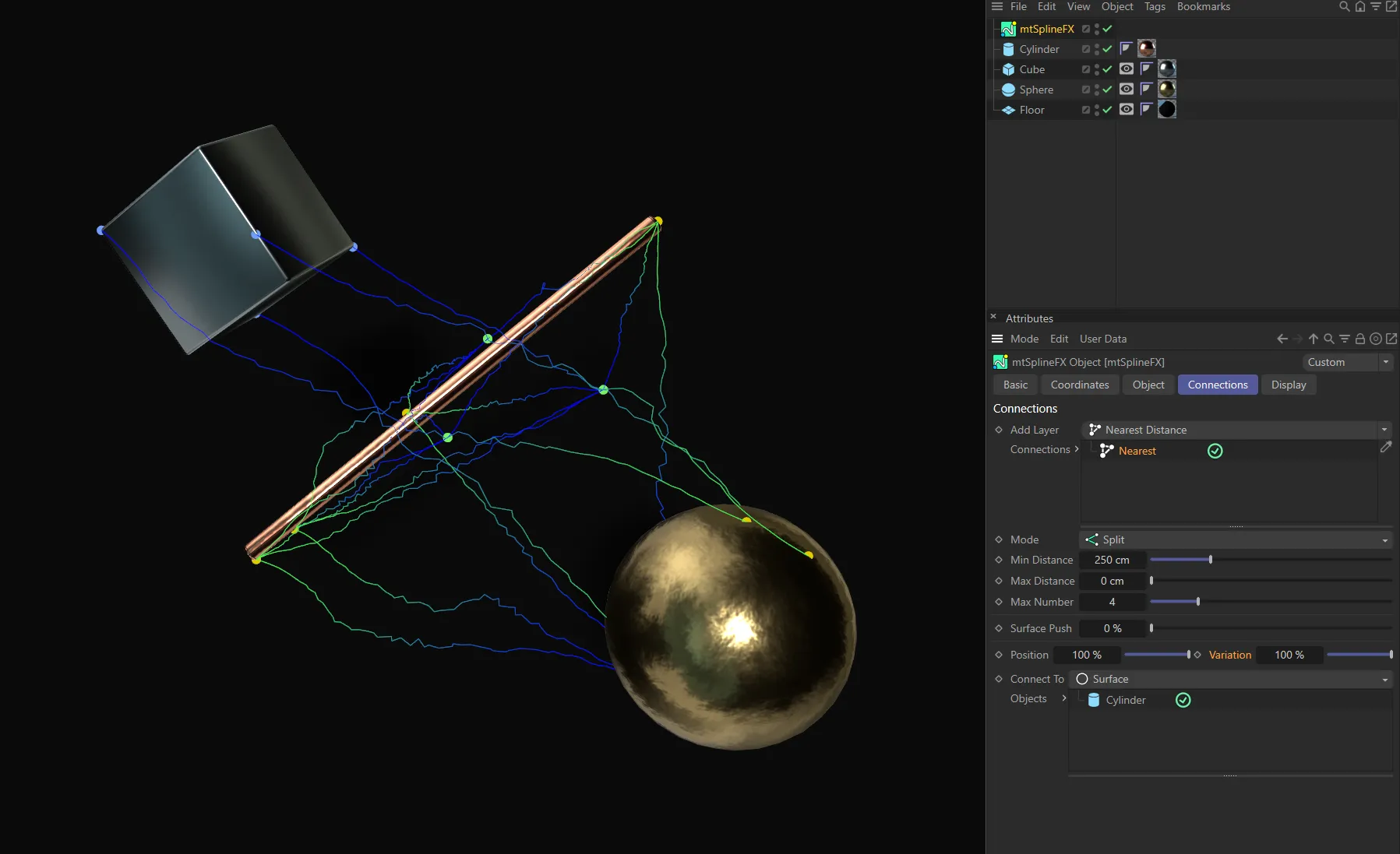
Here, with Variation set at 100%, every spline has a different starting point.
Connect To
Section titled “Connect To”Set as Points, by default, this defines where, on the connecting object, the generated points should be.
The alternative setting is Surface.
Points
Section titled “Points”The generated points should be on existing vertices of the connecting object.
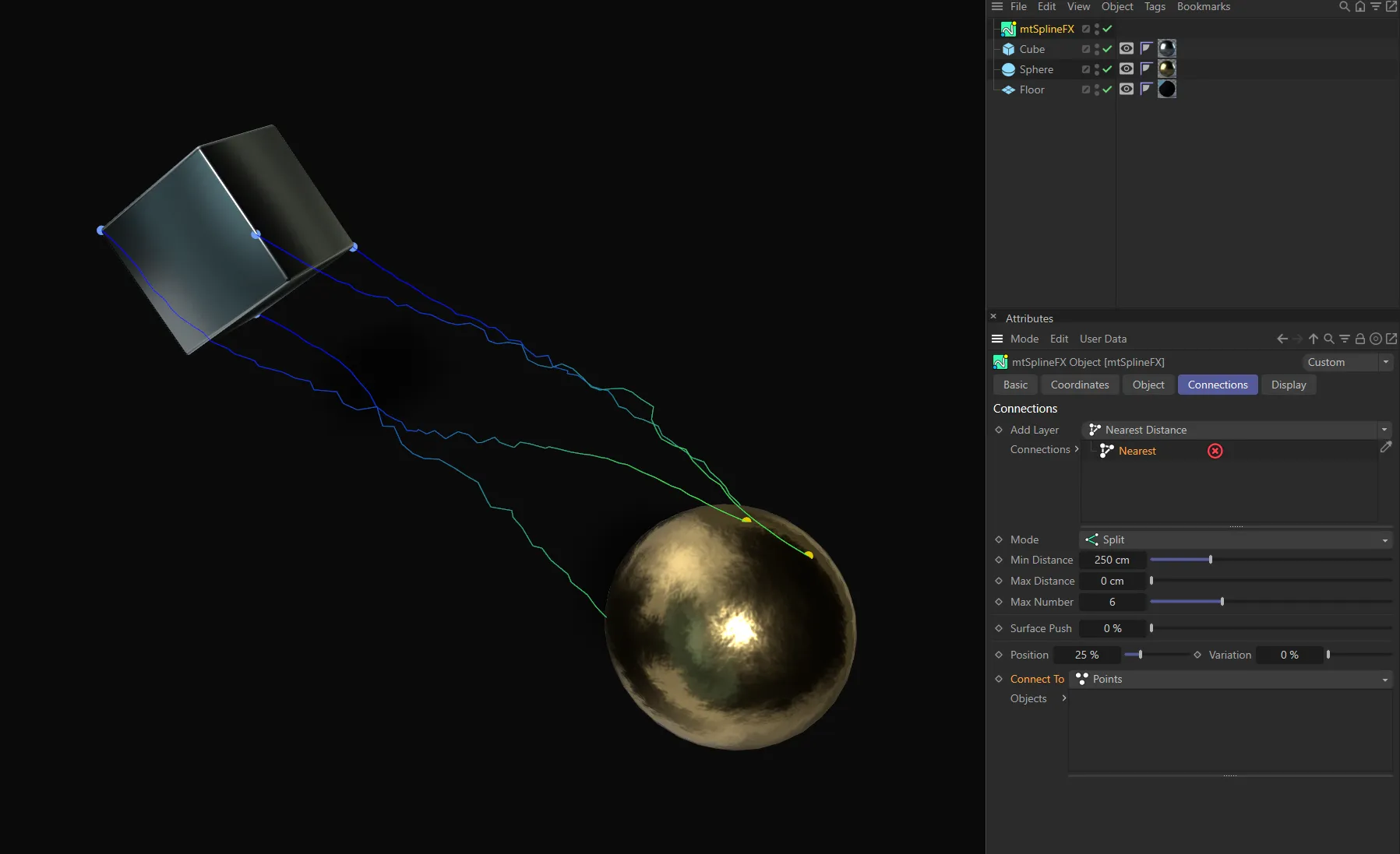
Connect To set as Points, with Connections disabled.
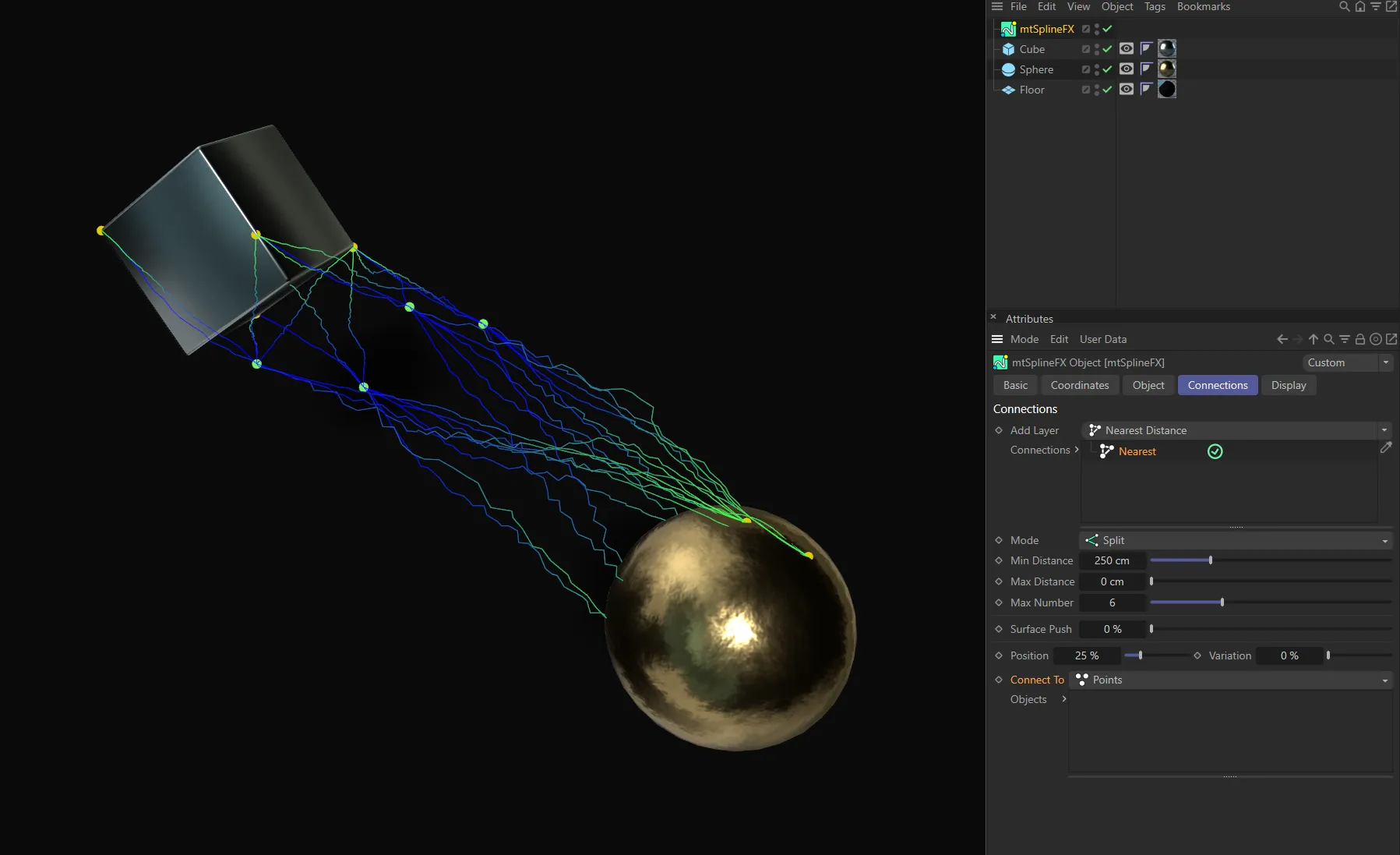
Connect To set as Points, with Connections enabled, in the Nearest connection mode.
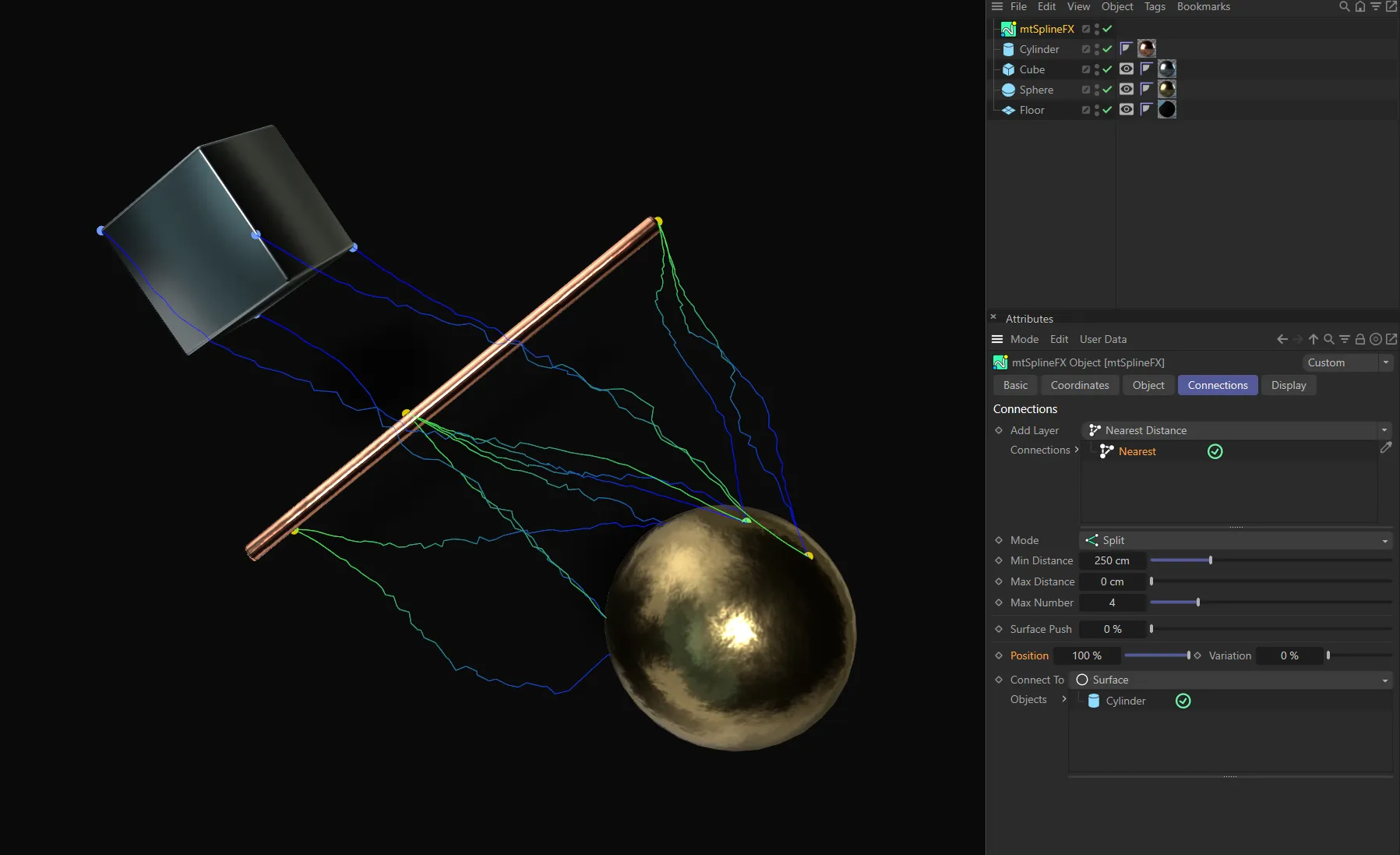
Surface
Section titled “Surface”The generated points should be on a random surface of the connecting object.
Connect To set as Surface, with Connections disabled.
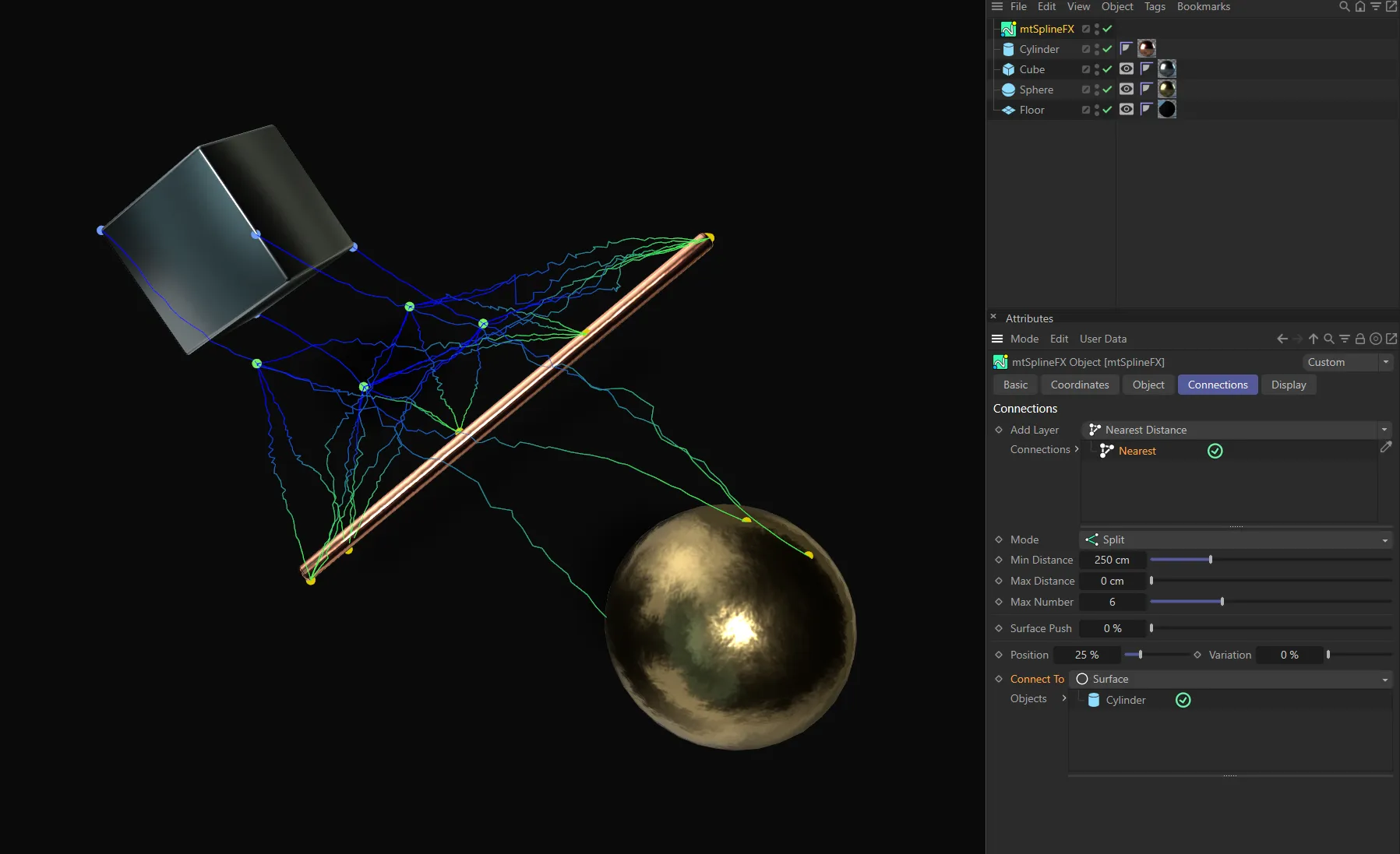
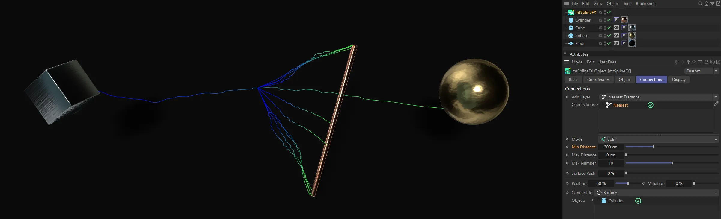
Connect To set as Surface, with Connections enabled, in the Nearest connection mode. The Cylinder is dropped in the Objects list, with connecting points on its surface.
Objects
Section titled “Objects”If the mode is Connections, this is the list of objects which will have a random point generated on their surface for use as an endpoint.
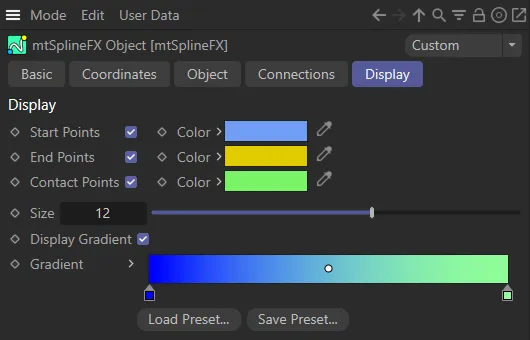
Display tab
Section titled “Display tab”General options to change the display of splines, connections and contact points.
Copyright © 2026 INSYDIUM LTD. All rights reserved.