nxFluids - FLIP/APIC solver parameters
The FLIP and APIC solvers are grid-based fluid simulation methods that transfer particle data to and from a background velocity grid each frame.
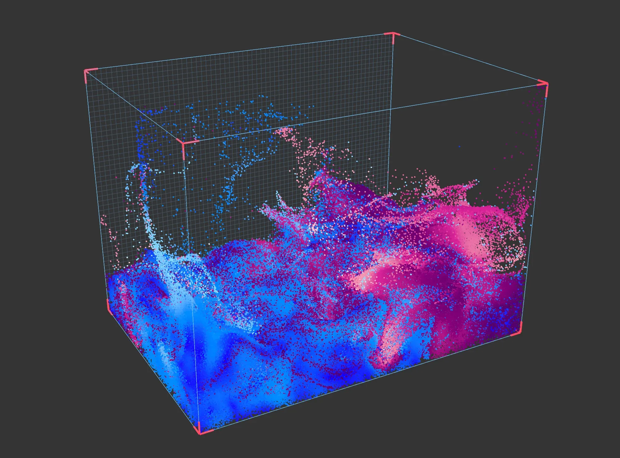
FLIP (Fluid-Implicit-Particle) blends grid-based and particle-based velocity updates, with the blend ratio controlled by the FLIP fraction parameter. APIC (Affine Particle-in-Cell) uses an affine velocity transfer that preserves more angular momentum and generally produces a more energetic, swirling result.
Both solvers share the same set of parameters, with the exception of FLIP fraction, which is only available when the FLIP solver is selected.
Object Properties
Section titled “Object Properties”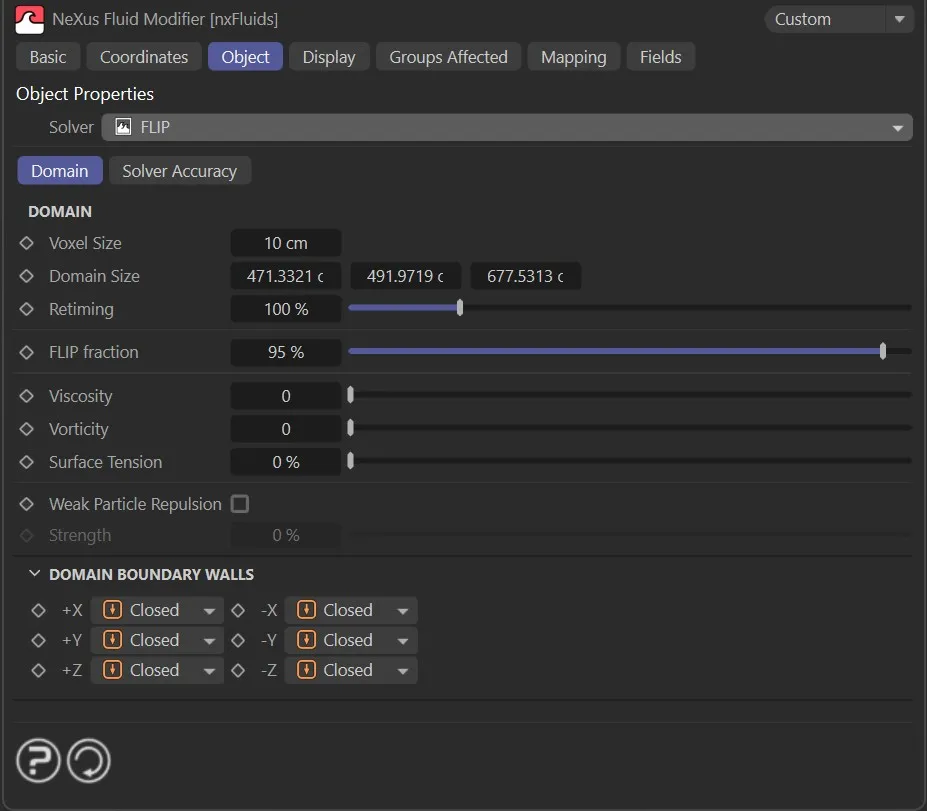
Domain tab
Section titled “Domain tab”Voxel Size
Section titled “Voxel Size”The size of each voxel in the simulation grid.
Smaller values produce a finer grid with more detail. Larger values produce a coarser grid that simulates faster.
Domain Size
Section titled “Domain Size”The size of the simulation domain along each axis.
Particles that leave the domain are handled according to the Domain Boundary Walls settings.
Retiming
Section titled “Retiming”Scales the simulation time step as a percentage.
A value of 100% runs the simulation at normal speed. Lower values slow the simulation and higher values speed it up. Values above 100% are possible.
FLIP fraction
Section titled “FLIP fraction”Controls the blend between pure PIC and pure FLIP velocity updates.
A value of 100% uses the full FLIP update, which is more energetic but can introduce noise. Lower values introduce more PIC damping, which reduces noise but also dissipates energy.
Viscosity
Section titled “Viscosity”The viscosity of the fluid.
Higher values produce a thicker, more resistant fluid. A value of zero produces an inviscid fluid.
Vorticity
Section titled “Vorticity”The strength of vorticity confinement applied to the velocity field.
This adds rotational energy to the simulation, producing more swirling and turbulent behaviour.
Surface Tension
Section titled “Surface Tension”The surface tension of the fluid.
Higher values cause the fluid surface to resist deformation and pull towards a minimal area.
Weak Particle Repulsion
Section titled “Weak Particle Repulsion”If enabled, a weak repulsion force is applied between nearby particles.
This helps maintain a more uniform particle distribution and reduces clustering artefacts in the simulation.
Strength
Section titled “Strength”The strength of the weak particle repulsion force.
Domain Boundary Walls
Section titled “Domain Boundary Walls”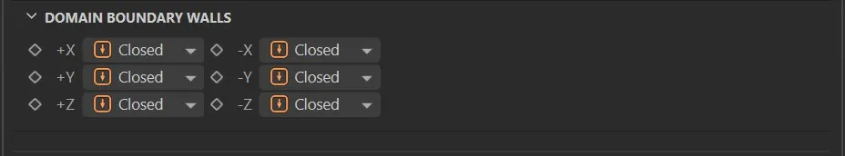
Controls how each face of the simulation domain boundary behaves when particles reach it.
Each of the six walls (+X, -X, +Y, -Y, +Z, -Z) can be set independently.
Set as Closed, by default.
The alternatives are Open and Kill.
Closed
Section titled “Closed”The boundary acts as a solid wall. Particles are reflected back into the domain.
The boundary is open. Particles can pass through and exit the domain.
Particles that reach this boundary are deleted.
Solver Accuracy tab
Section titled “Solver Accuracy tab”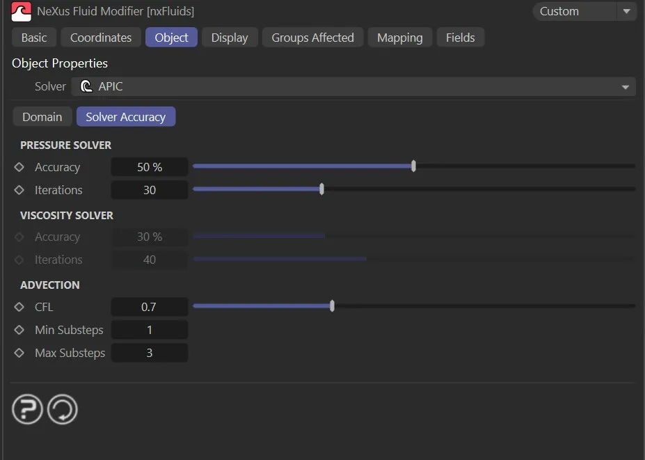
Pressure Solver
Section titled “Pressure Solver”Accuracy
Section titled “Accuracy”The convergence threshold for the pressure solver, as a percentage.
The solver stops early if this accuracy level is reached before the maximum number of iterations.
Iterations
Section titled “Iterations”The maximum number of iterations the pressure solver runs per substep.
Higher values allow the solver more time to converge, producing a more accurate result at the cost of additional processing time.
Viscosity Solver
Section titled “Viscosity Solver”Accuracy
Section titled “Accuracy”The convergence threshold for the viscosity solver, as a percentage.
Iterations
Section titled “Iterations”The maximum number of iterations the viscosity solver runs per substep.
Advection
Section titled “Advection”The Courant-Friedrichs-Lewy number used to determine the substep size.
Lower values produce more substeps per frame and a more accurate simulation. Higher values produce fewer substeps and simulate faster.
Min Substeps
Section titled “Min Substeps”The minimum number of substeps calculated per frame.
Max Substeps
Section titled “Max Substeps”The maximum number of substeps calculated per frame.
Display
Section titled “Display”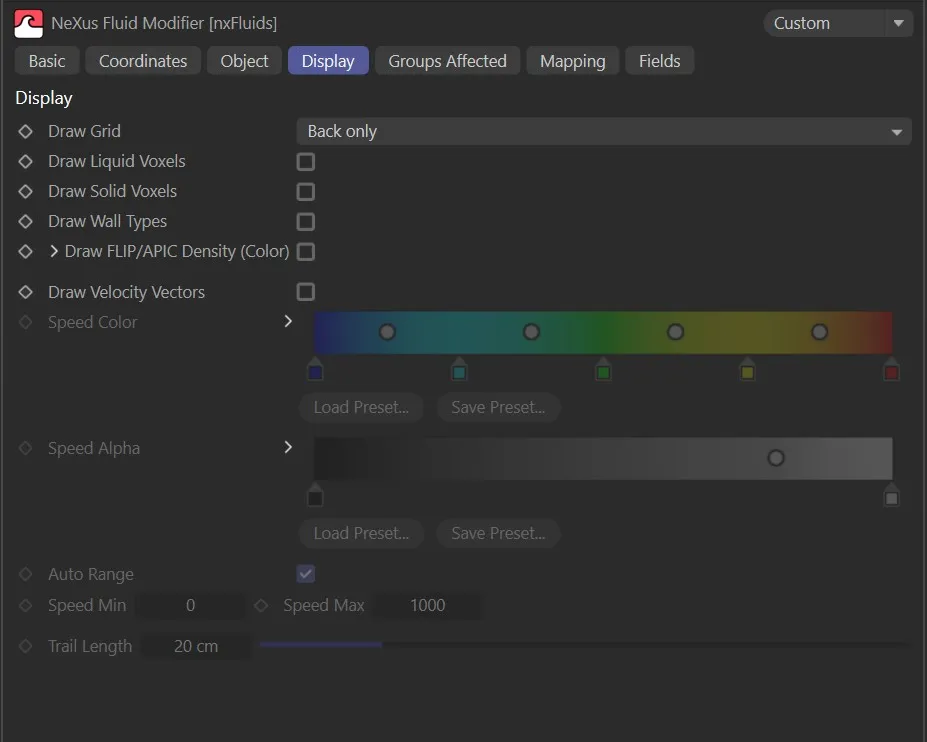
Draw FLIP/APIC Density (Color)
Section titled “Draw FLIP/APIC Density (Color)”If enabled, the fluid density is visualised in the viewport using the Density Color gradient.
Density Color
Section titled “Density Color”The gradient used to colour the fluid density visualisation.
The left end of the gradient corresponds to low density and the right end to high density.
Draw Grid
Section titled “Draw Grid”Controls how the simulation grid is drawn in the viewport.
Set as None, by default.
The alternatives are Voxels, Back only, Base only and Base and back.
Draw Liquid Voxels
Section titled “Draw Liquid Voxels”If enabled, the voxels containing liquid are drawn in the viewport.
Draw Solid Voxels
Section titled “Draw Solid Voxels”If enabled, the voxels containing solid obstacle data are drawn in the viewport.
Draw Wall Types
Section titled “Draw Wall Types”If enabled, the domain boundary wall type for each face is indicated in the viewport.
Draw Velocity Vectors
Section titled “Draw Velocity Vectors”If enabled, velocity vectors are drawn in the viewport to visualise the fluid velocity field.
Speed Color
Section titled “Speed Color”A gradient used to colour the velocity vectors by speed.
Speed Alpha
Section titled “Speed Alpha”A gradient used to control the opacity of the velocity vectors by speed.
Auto Range
Section titled “Auto Range”If enabled, the speed range is determined automatically from the current simulation data.
When disabled, the range is set manually using Speed Min and Speed Max.
Speed Min
Section titled “Speed Min”The speed value that maps to the left end of the Speed Color and Speed Alpha gradients.
Speed Max
Section titled “Speed Max”The speed value that maps to the right end of the Speed Color and Speed Alpha gradients.
Trail Length
Section titled “Trail Length”The length of the velocity vector trails drawn in the viewport.
Fluid Tag
Section titled “Fluid Tag”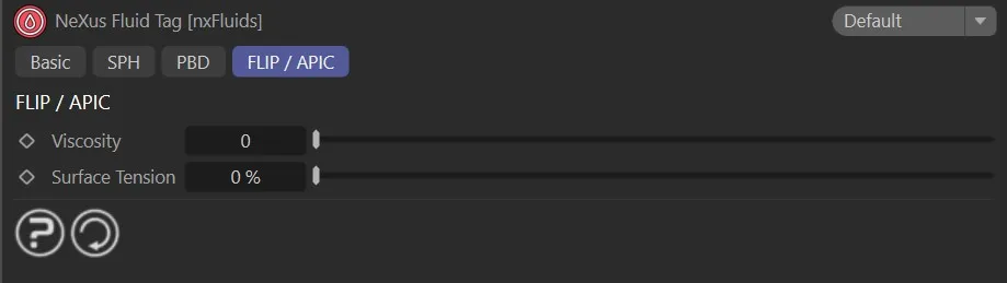
A Fluid Tag can be applied to a particle emitter to override the solver-level fluid properties for the particles from that emitter.
The FLIP / APIC section of the tag provides the following per-emitter overrides.
Viscosity
Section titled “Viscosity”Overrides the Viscosity value from the solver for particles from this emitter.
Surface Tension
Section titled “Surface Tension”Overrides the Surface Tension value from the solver for particles from this emitter.
Copyright © 2026 INSYDIUM LTD. All Rights Reserved.