GradientUV Shader User Guide
The GradientUV Shader uses a 2D gradient, which mixes four colors.
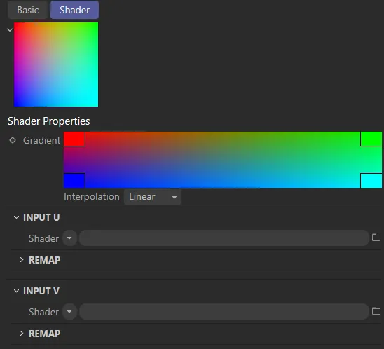
The default 2D gradient, with its four color states: red, green, blue and cyan.
This gradient is then applied to the terrain, using its UV coordinates, as seen in the image below.
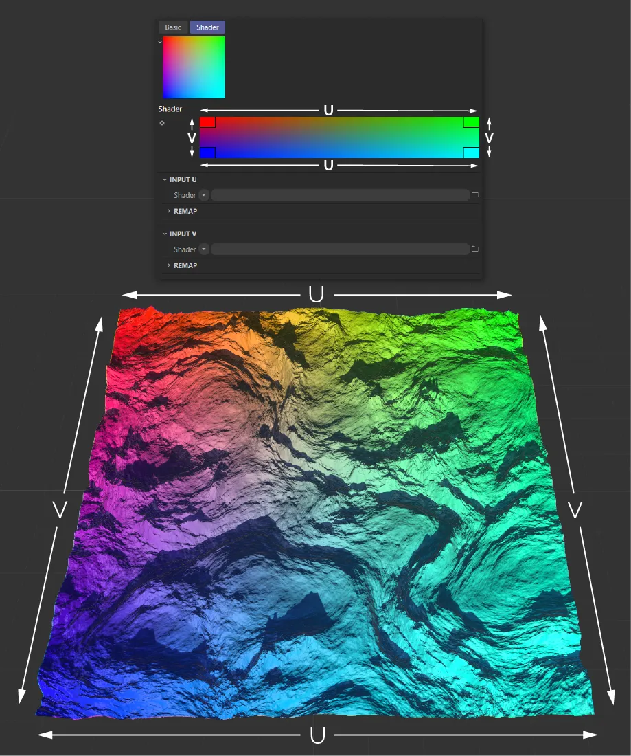
A terrain textured using a GradientUV Shader, in its default settings.
The U and V can each be assigned shader inputs.
This makes it possible, using a Terrain Operator Shader, to mix the four colors of the 2D gradient using two terrain properties, like Altitude and Slope (this will be explained in full, further down the page).
First, it is important to properly understand the 2D gradient, how it relates to the terrain’s UVs and how to use the remap controls to make artistic adjustments.
Each Input, U and V, has a remap curve.
A linear curve will map an equal transition from color to color, along the length of the gradient.
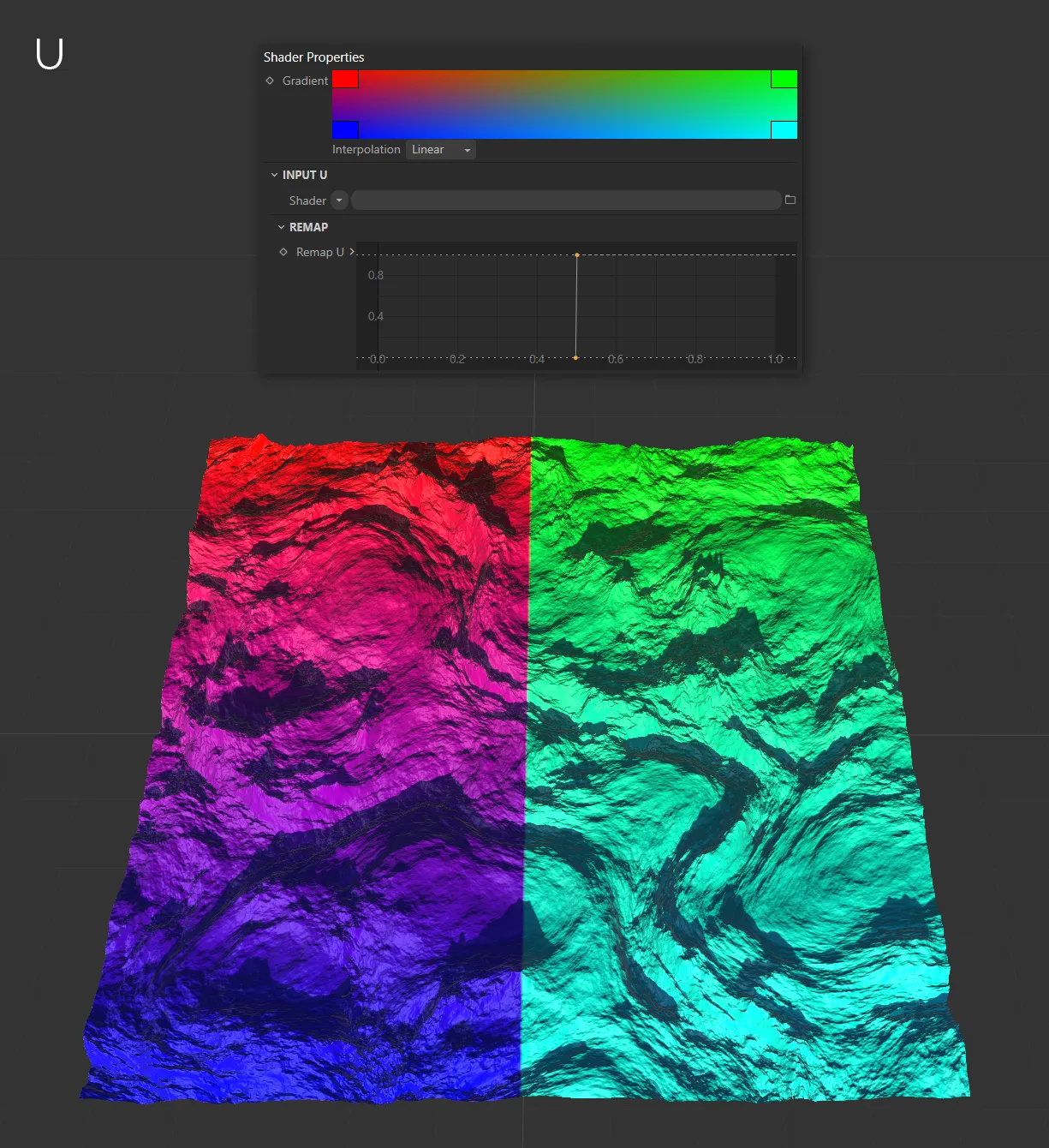
In the example below, you can see a 50% mix of red and green halfway along the horizontal U (and also, the same 50% mix of blue and cyan at the bottom).
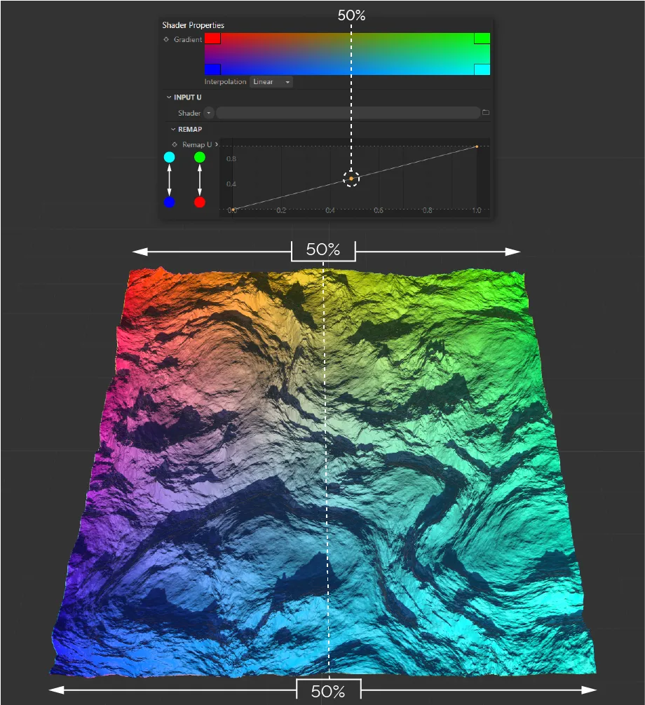
The Remap U curve, with a linear setting.
This can be remapped by adjusting the curve.
In the example below, the 50% point between red and green, at the top, and blue and cyan, at the bottom, has been moved so that the 50% mix is achieved nearer the left side of the terrain.
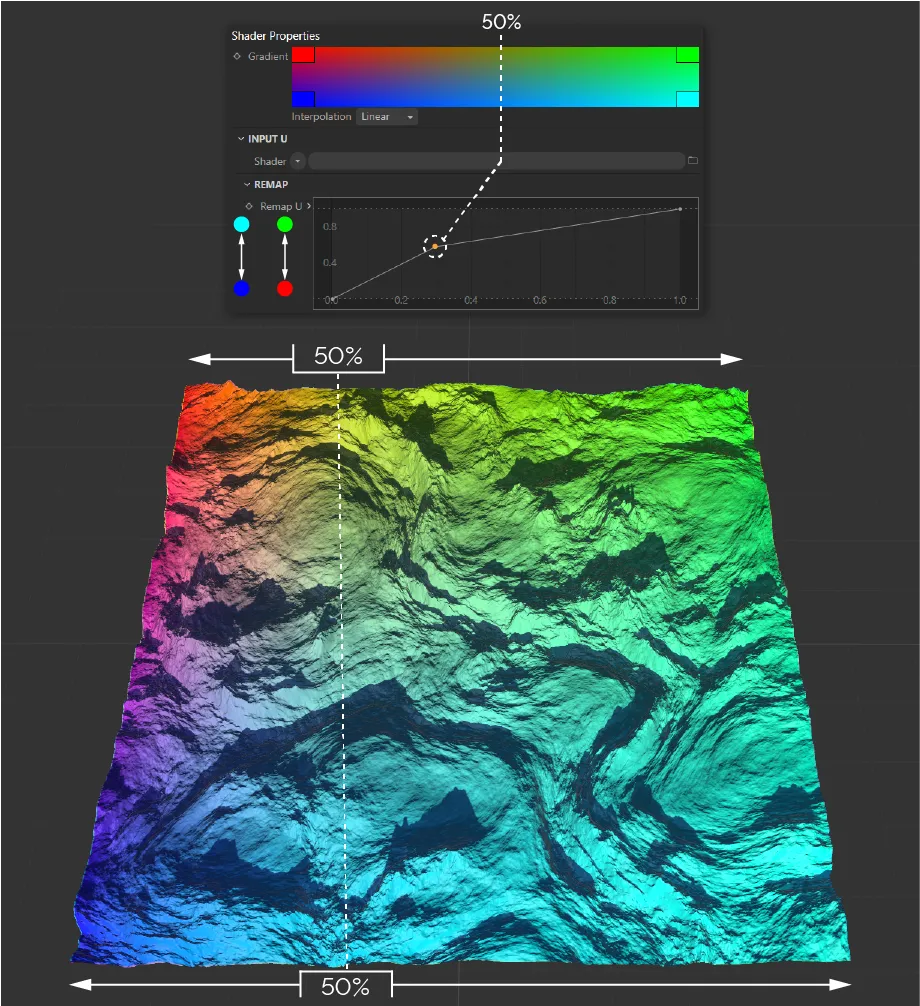
A slightly different Remap U curve setting changes the effect on the terrain, here.
We can remove any fade between colors completely, by applying an aggressive linear curve.
In the example below, the curve means that the gradient is 100% red, until the halfway point, and then becomes 100% green.
There is no fade between colors.
This is the same for blue to cyan.
This Remap U curve setting is (as explained above) removing any fading between colors.
The Input V works in the same way.
In the example below, the input curve means that the V gradient on the bottom of the terrain is 100% blue until the halfway point and then becomes 100% red etc.

The identical curve setting, but this time it is on the Remap V curve.
By applying the same curve to both the U and V input, any color mixing is removed and only the four gradient colors are used.
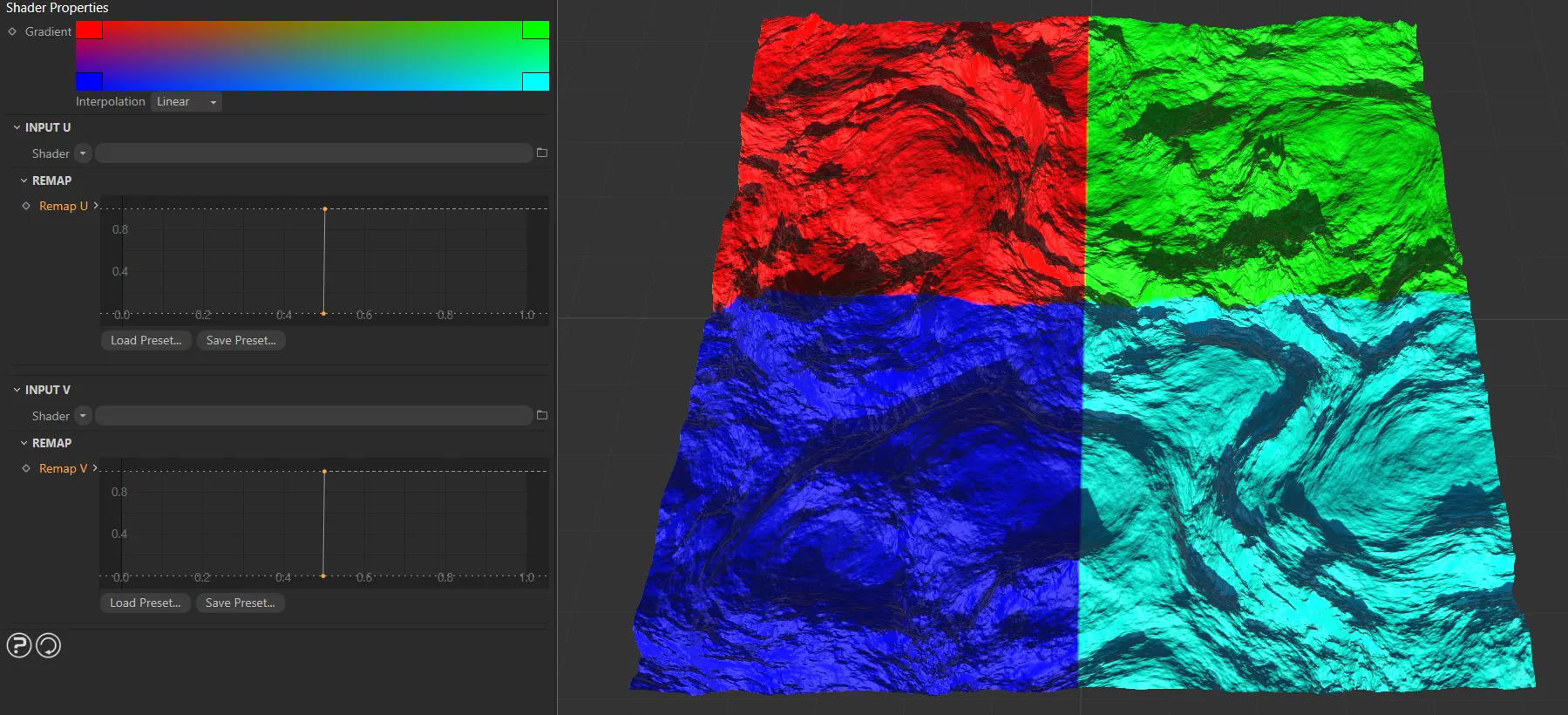
In this image, the same setting is applied on both the Remap U and Remap V curves.
In the above examples, the U and V inputs are in their default settings.
As already stated, this mixes the colors using the UV coordinates of the terrain, clearly illustrating the relationship between the gradient and the terrain.
The upper left corner of the gradient is red and the upper left corner of the terrain is red etc.
However, the true power of the GradientUV Shader is unlocked when shaders are used in the U and V inputs.
This makes it possible to use noises and terrain features, like Altitude, Slope and erosion deposits, to mix the four gradient colors.
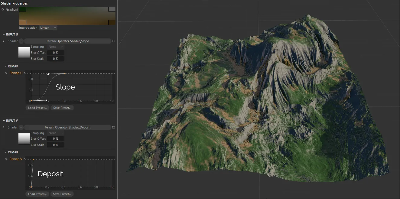
In this example, the four gradient colors are being mixed, using two Terrain Operator Shaders.
The U Input, above, has a Terrain Operator Shader, which is referencing the tfTerrain Slope map.
The V Input has a Terrain Operator Shader, referencing the Deposit Map from the tfTerrain Hydraulic Erosion filter.
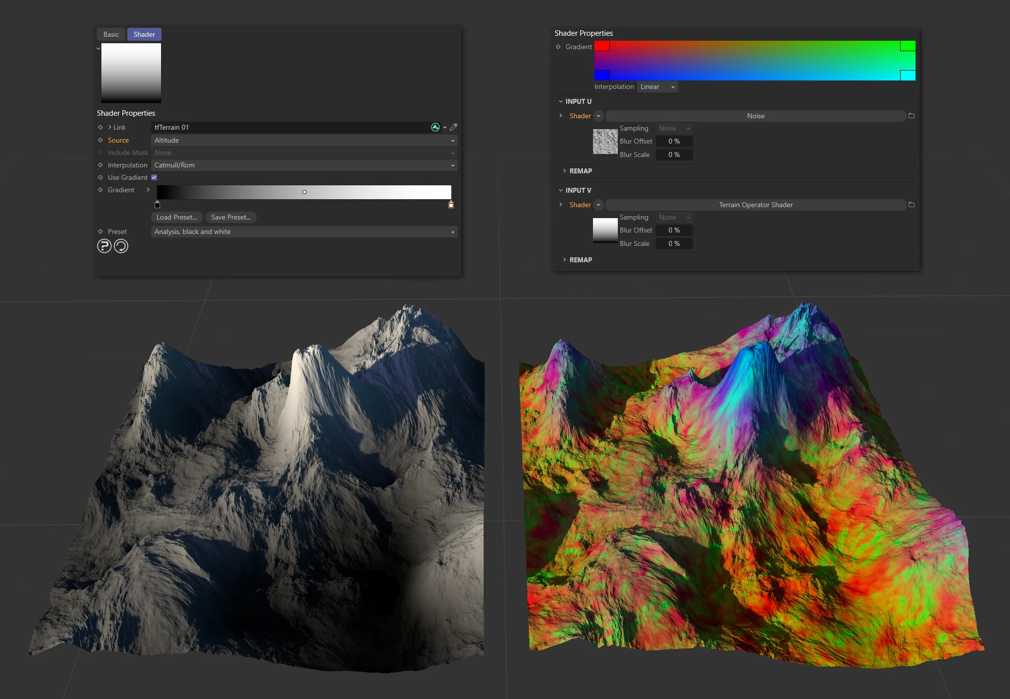
To best understand how shader inputs affect the color mix, begin by using a Noise shader, in the U, and keep the V at default.
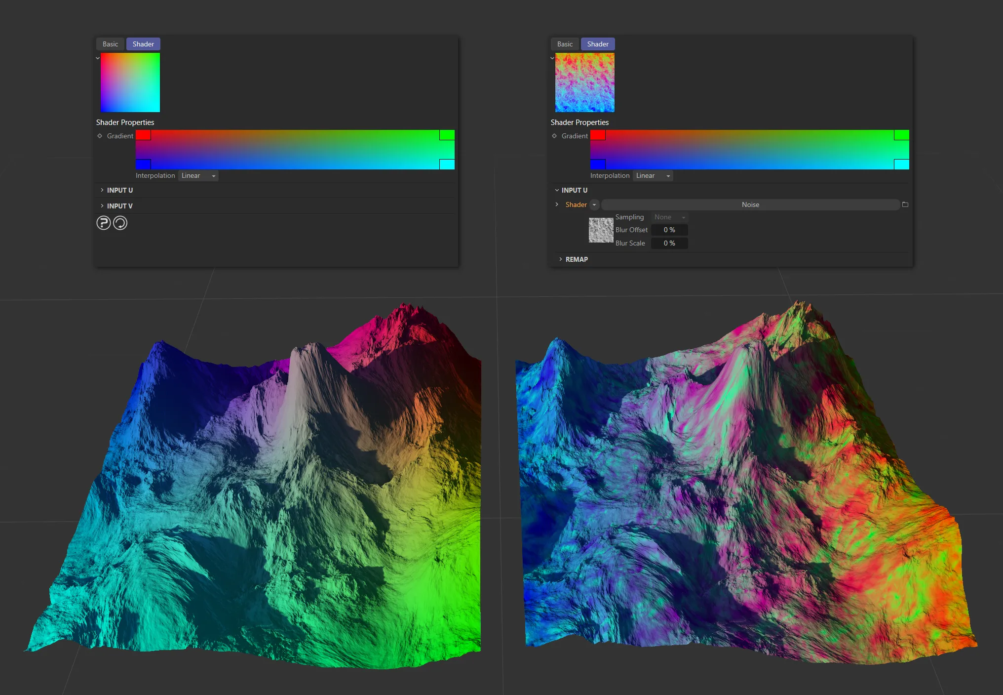
In this image, the terrain on the left is there for reference; it has the default settings for U and V inputs. The terrain on the right has a Noise shader in the U input, significantly changing the application of the gradient to the terrain.
At the top edge of the terrain, the U gradient is red, where the noise color value is 0 (black) and green where the noise color value is 1 (white).
At the bottom edge, the U gradient is blue where the noise color value is 0, and cyan where it is 1.
You are now able to further control the distribution of your U noise gradients, by adding a shader to the V input.
Here a Terrain Operator Shader is being used to get the altitude data from the terrain, enabling the blue to cyan noise to be applied to the higher parts of the terrain and the red to green noise to the lower parts.
The left hand Terrain is there for reference; it is displaying the black and white altitude data.
This altitude data is being used in the Input V via a Terrain Operator Shader.
The result is that the highest parts of the terrain have the blue to cyan noise gradient.
The lowest parts have the red to green noise gradient.
To make this more obvious, you can adjust the Input V (altitude data) remap curve.
This increases the contrast, removing most of the greys.
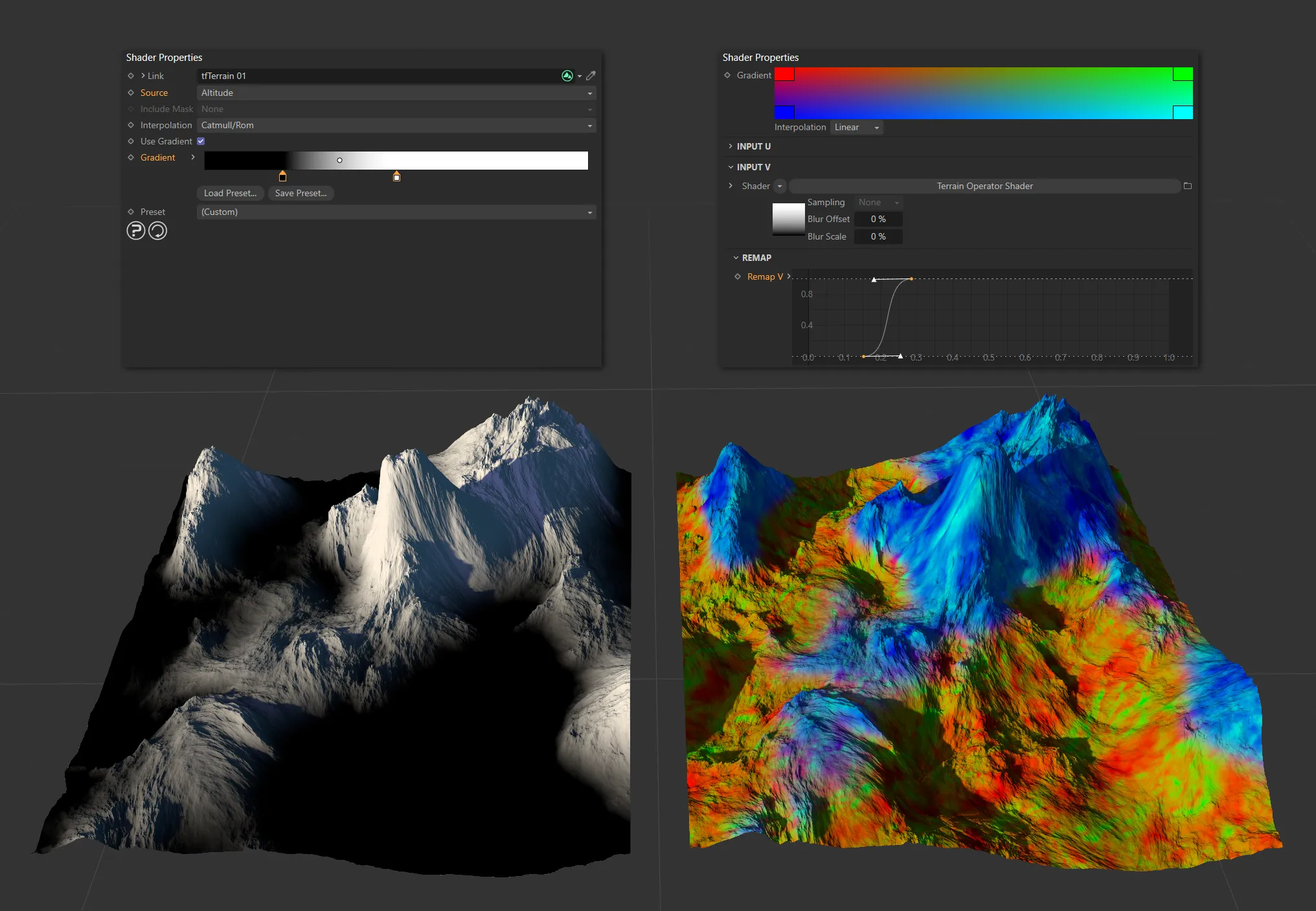
The terrain on the left displays the high-contrast altitude data. The terrain on the right displays the UVGradient Shader color mix.
Now the high peaks have been isolated from the low valleys, the gradient colors can be adjusted to something more realistic.
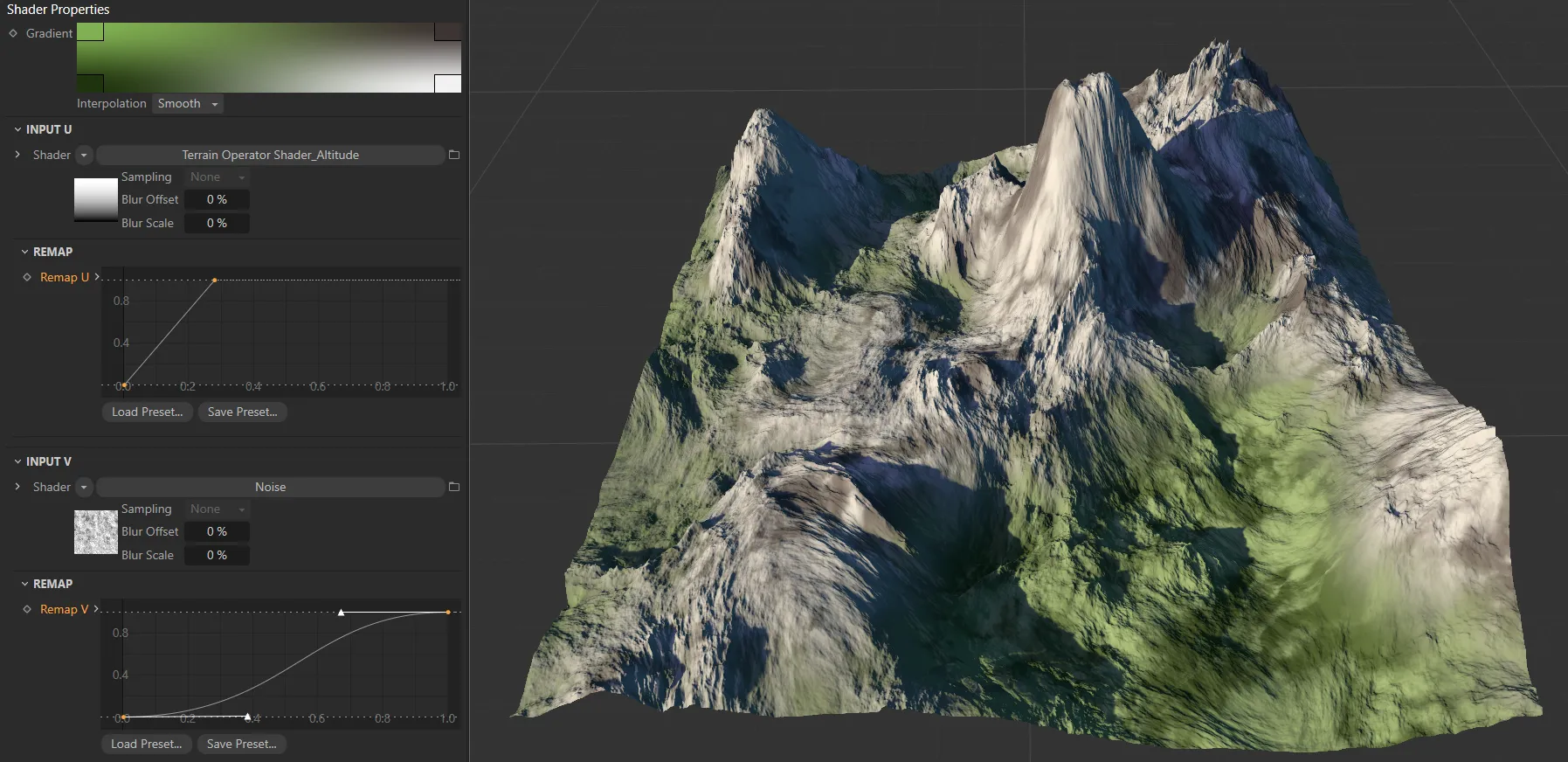
In this image, a rocky colored noise gradient is applied to the peaks and a grassy colored noise gradient applied to the valleys.
Copyright © 2026 INSYDIUM LTD. All rights reserved.