Terrain Operator Shader
The Terrain Operator Shader can be used in rendering, to create intricately detailed materials or in 3D simulations to isolate effects to specific terrain features.
Use this shader to access the 2D output of individual operators or the combined 2D output of tfGroups and tfTerrains.
The Terrain Operator Shader can be accessed from any object that uses the Texture drop-down menu.
This could be a material channel, an X-Particles modifier or a node within a 3rd party render engine.
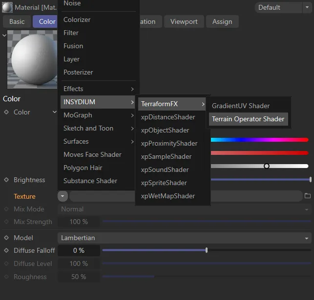
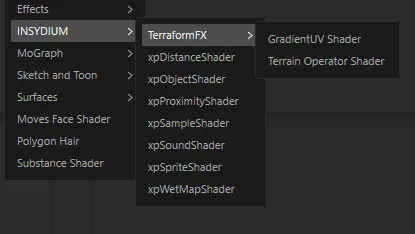
Menu access to the Terrain Operator Shader.
Terrain Operator Shader menu.
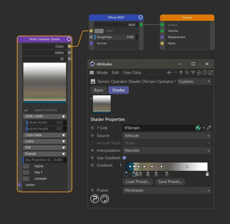
The Terrain Operator Shader loaded into a Cycles 4D Image Texture node.
Link the operator or the terrain object that you want to render by dragging and dropping into this link field or using the eyedropper tool.
This animation shows the Terrain Operator Shader being used in the color channel of a material. The shader can reference any part of the TerraformFX hierarchy for different rendering effects. It can also be used to isolate certain terrain features.
Source
Section titled “Source”Set as Altitude, by default.
The alternatives for the source data are: Slope or Fields Mask.
Filter operators also have the Difference Map option.
In addition, there are some operator specific modes, for example, the Hydraulic Erosion filter has Erode Map and Deposit Map options.
Animation to demonstrate the different settings available for the Source parameter.
Altitude
Section titled “Altitude”This renders the operator’s height map.
By default, the left side of the gradient will be applied to the lowest altitudes and the right side will be applied to the high altitudes.
Renders the operator’s slope map (first derivative of the height map).
Flat plains will render black, slopes will render brighter with increasing steepness.
Fields Mask
Section titled “Fields Mask”Renders the mask that is created by the operator’s field list.
If you have constrained operators locally using fields settings, you can now do the same with the shader.
This option is not available if a terrain object has been linked.
Difference Map
Section titled “Difference Map”Renders the difference between the terrain before and after the filter operator.
Include Mask
Section titled “Include Mask”Set as None, by default. Data source options are: Fields, Shader or Fields + Shader.
This parameter allows you to render the fields mask’s effect.
This option is only available for the Source settings of Altitude and Slope.
Use Custom Direction
Section titled “Use Custom Direction”Only available if Source is set to Slope.
This setting allows you to alter the way in which Slope is calculated.
By default, slope enables you to differentiate steep and flat features.
This allows you to, for example, restrict grass to only flatter parts of your landscape.
The slope is calculated by working out the difference between the normal of a terrain point and the +Y direction.
However, it may be desirable to change this.
For example, you may want to restrict grass to south-facing hills.
To do this, activate Use Custom Direction and change the Direction controls from the default Y+ (up) to an X or Z direction of your choice, in the parameter below.
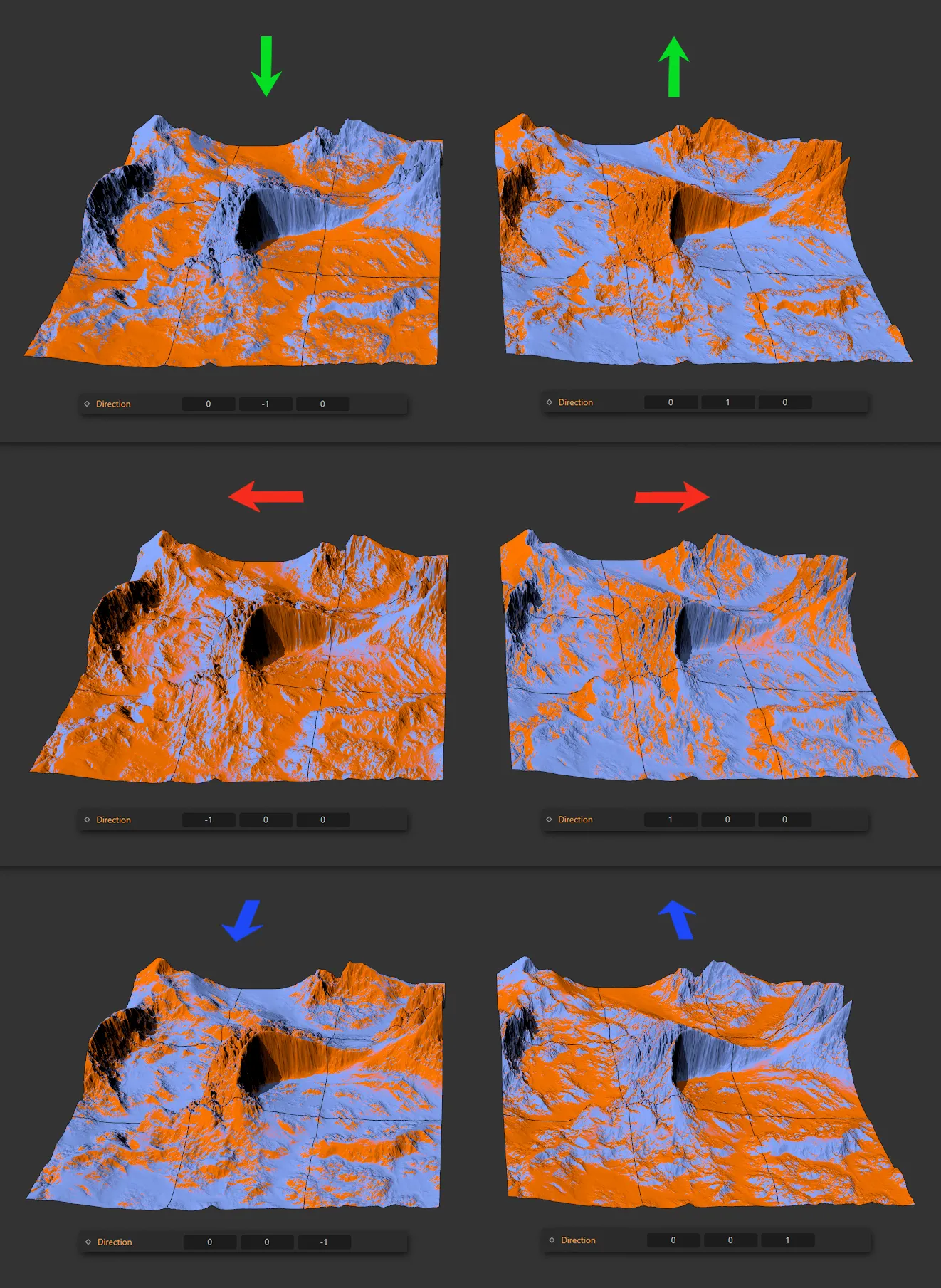
These images, together with the applicable settings, illustrate the different effect of the Custom Direction parameter between the Direction values of -1 and 1 in the X-axis (top row), Y-axis (center) and Z-axis (bottom).
Direction
Section titled “Direction”Slope is defined as the angle between the surface normal and a reference vector.
By default, that reference vector is (0,1,0), pointing in +Y direction.
Use these axes values (X, Y and Z) to create a custom reference direction.
For example, inputting (1,0,0) would give a reference direction of +X.
Interpolation
Section titled “Interpolation”Set as Hermite, by default.
The alternative settings are: Nearest, Bilinear, Cosine and Bicubic
Nearest
Section titled “Nearest”This mode does not interpolate at all, the result looks pixelated, but it calculates quickly.
Bilinear
Section titled “Bilinear”Also quite quick to calculate, using a simple bilinear interpolation, this mode is smooth, but gives hard edges.
Cosine
Section titled “Cosine”Cosine interpolation creates a smooth result, without steps.
Bicubic
Section titled “Bicubic”Rendering is slightly slower than the other modes.
This mode uses a bicubic interpolation. It is very smooth, detailed and high quality.
Hermite
Section titled “Hermite”This is very smooth, detailed and high quality, but rendering is slightly slower than the other modes.
Use Gradient
Section titled “Use Gradient”Enabled by default, to allow use of the gradient to color the shader’s output.
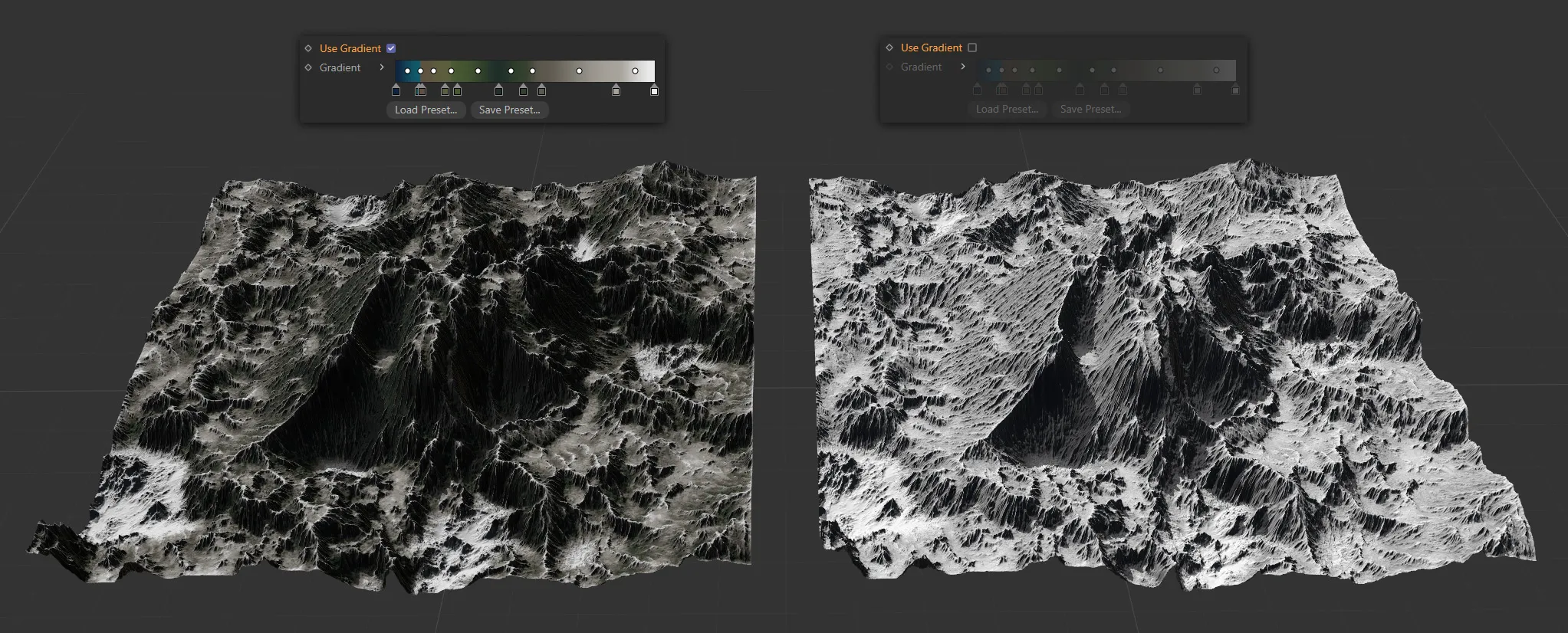
The terrain operator shader on the left has Use Gradient enabled, applying the colours from the gradient, as instructed by the link’s source map. The terrain on the right has Use Gradient disabled, so the gradient is disregarded, automatically mapping black and white.
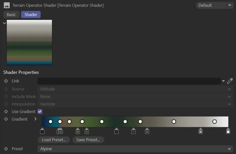
Gradient
Section titled “Gradient”Use the drop-down arrow to access the usual settings and options.
Load Preset
Section titled “Load Preset”Load in a preset gradient from here.
Save Preset
Section titled “Save Preset”Save custom settings here.
Preset
Section titled “Preset”All eleven of the preset geographic set color options are available.
There is also a (Custom) option which allows customisation and is automatically set when alterations are made to the preset gradients.
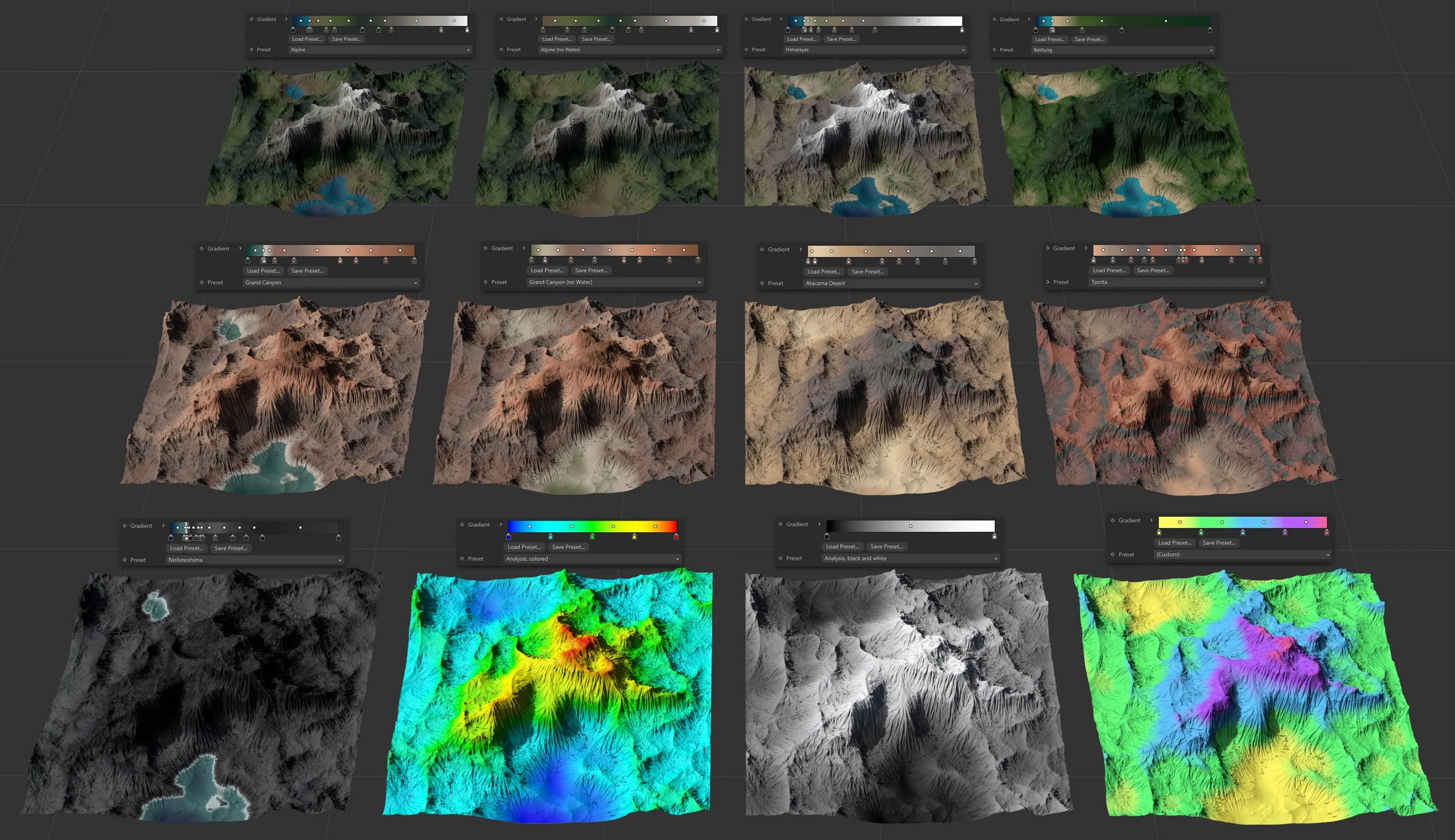
Image to show the eleven Preset terrain settings available, as well as the (Custom) setting.
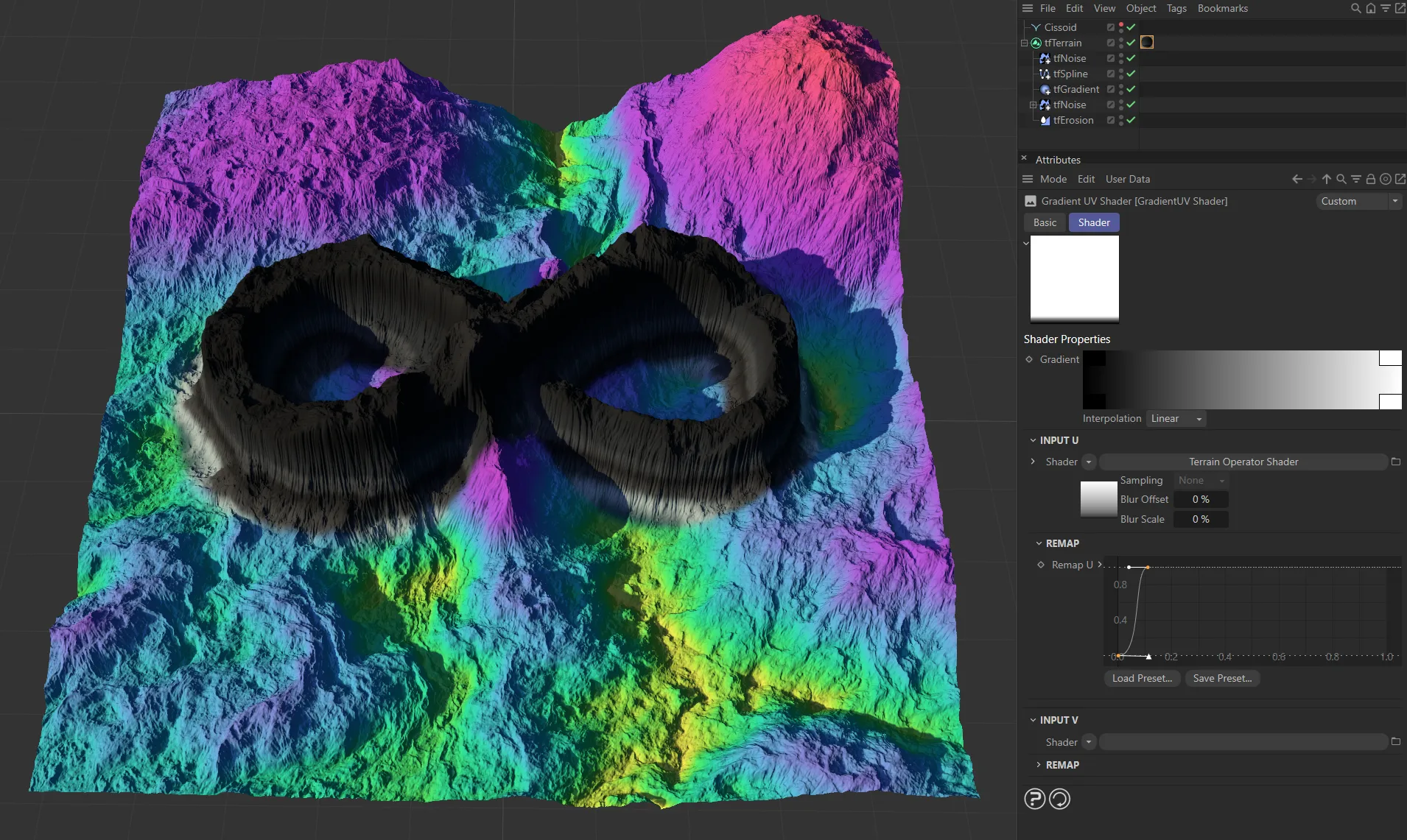
GradientUV Shader
Section titled “GradientUV Shader”The GradientUV Shader can be accessed from any object that uses the Texture drop-down menu.
This could be a material channel, an X-Particles modifier or a node within a 3rd party render engine.
Menu access to the GradientUV Shader.
In addition, the GradientUV Shader can be accessed from operators’ Masking tab, by enabling the Shader parameter and using the Link drop-down menu.
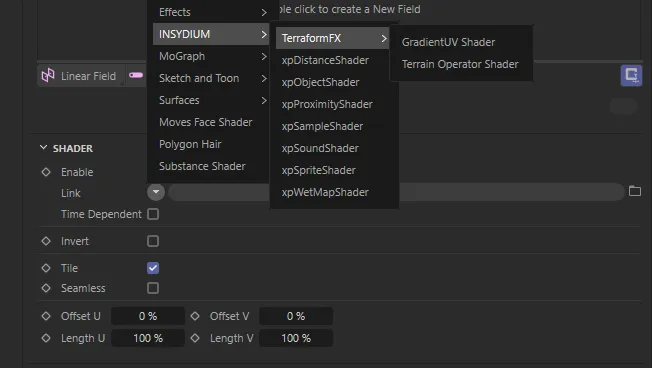
Access via the Masking tab, by enabling the Shader parameter.
The GradientUV Shader allows more complex coloring without having to juggle multiple gradients and masks.
The shader provides two sub channels as input, a 2D gradient, as well as curves for value remapping.
In rendering, the GradientUV will sample the two input shaders, and use their brightness (average value of their RGB output) as U and V value to sample from the 2D gradient.
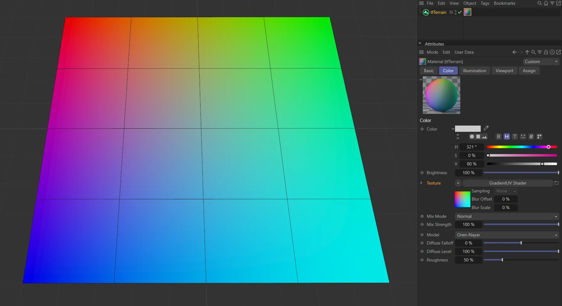
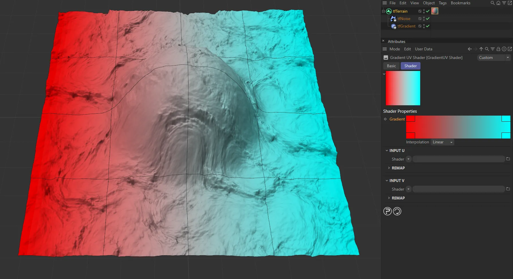
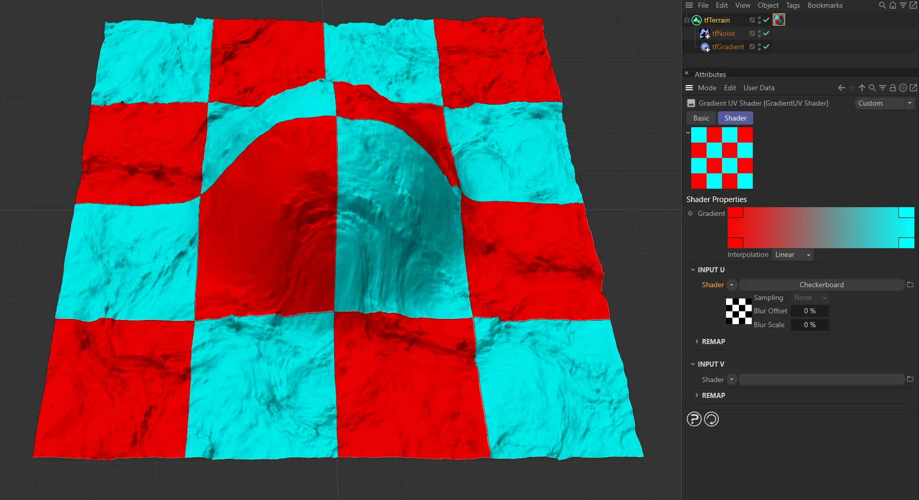
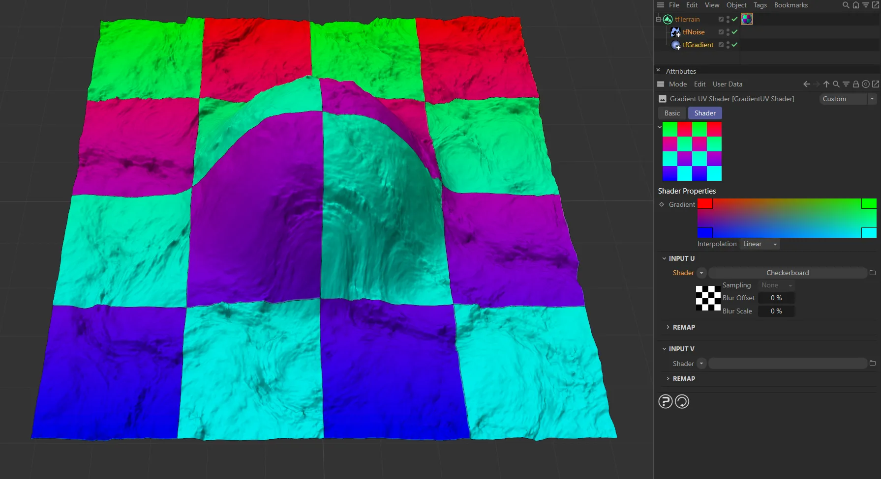
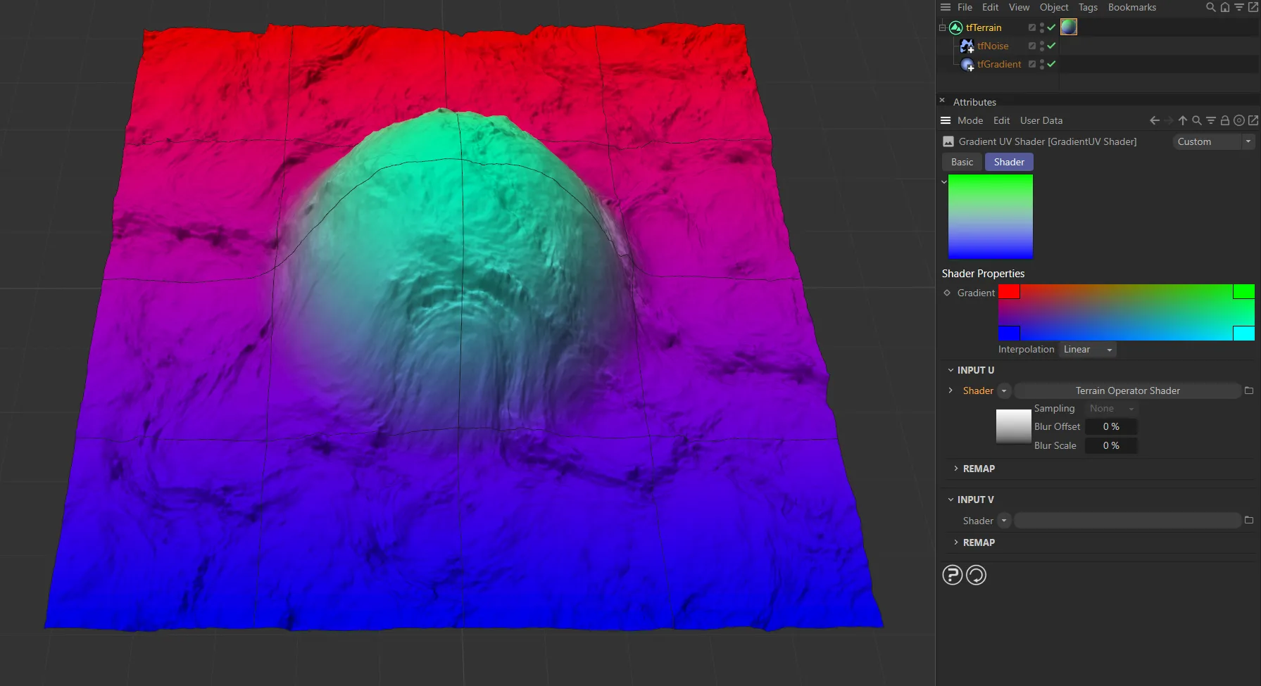
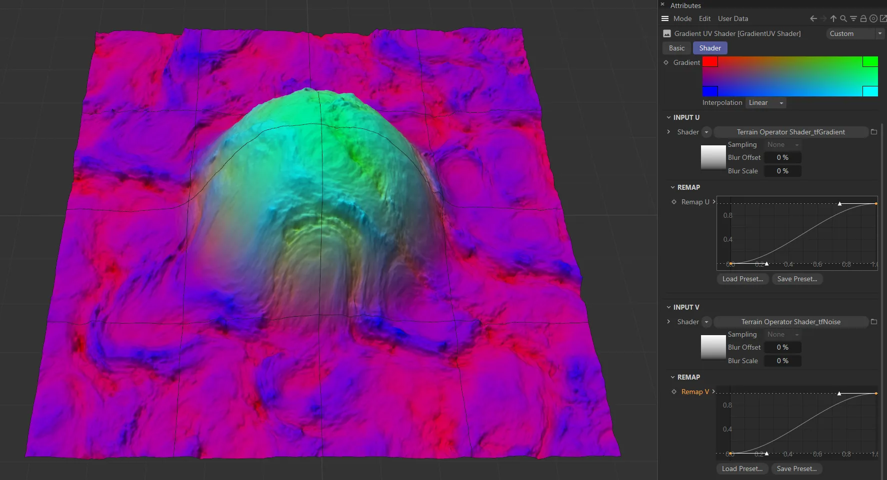
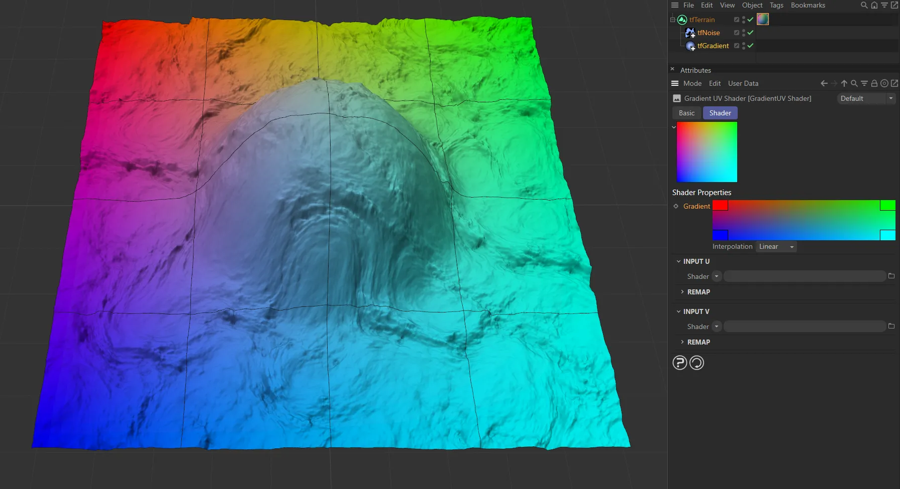
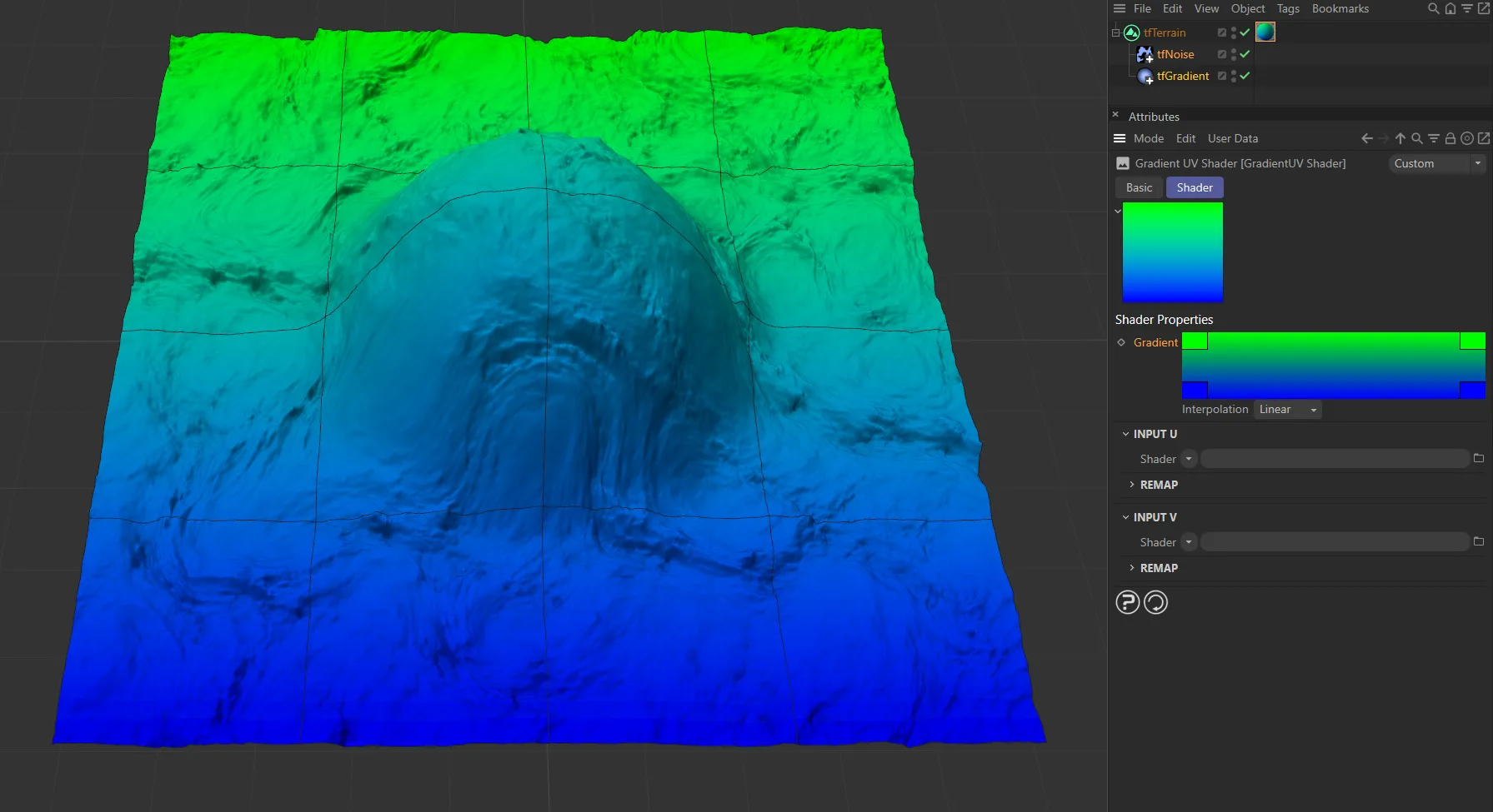
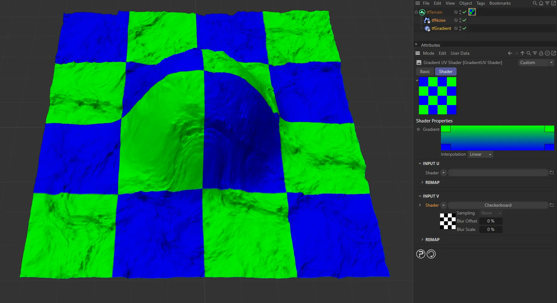
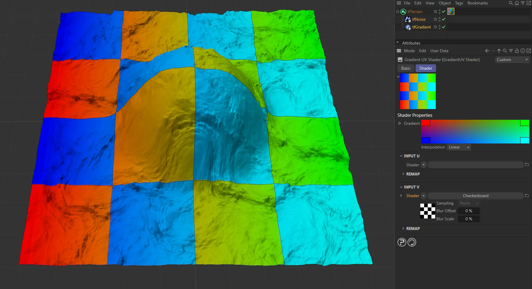
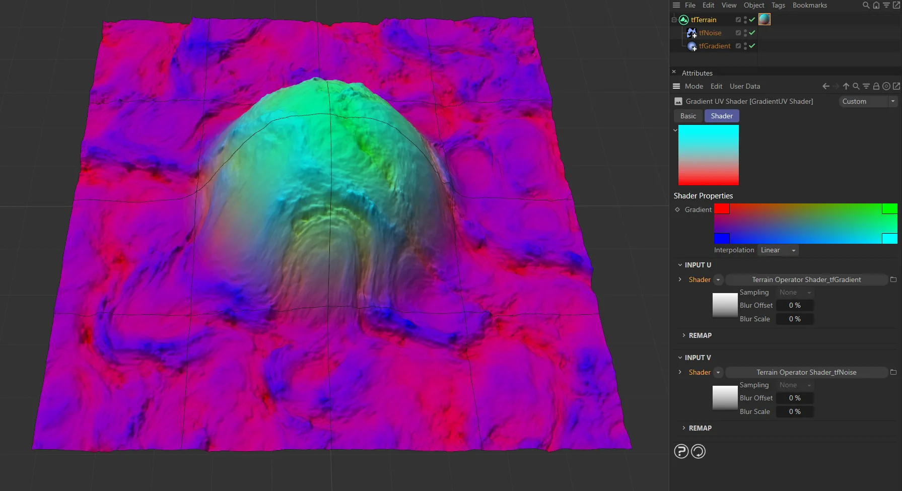
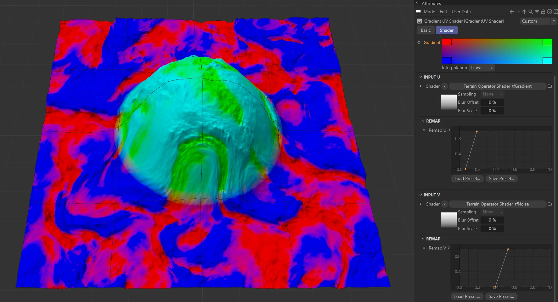
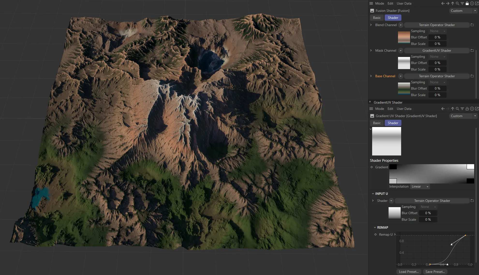
As there are two input channels, you can blend four color ‘states’, as illustrated in the Gradient setting above.
So, rather than masking two independent gradients of two Terrain Operator Shaders on top of each other, it is possible to get all blended intermediate states of both Terrain Operator Shaders.
Copyright © 2026 INSYDIUM LTD. All rights reserved.