Display
This tab controls the appearance of particles in the editor, along with the head-up display (HUD) and the modifier field display.
Particles tab
Section titled “Particles tab”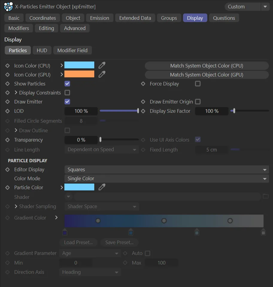
Particles tab menu.
Icon Color (CPU and GPU)
Section titled “Icon Color (CPU and GPU)”You can choose any color for the emitter icon in the viewport.
Simply choose the color from this setting.
This color will also affect the icon color when the emitter is in Controlled Only mode.
The icon changes color when this parameter is changed.
Match System Object Color
Section titled “Match System Object Color”If the emitter is part of an xpSystem object hierarchy, you can click this button to set the emitter icon color to be the same as its parent xpSystem object.
Show Particles
Section titled “Show Particles”If this is unchecked, no particles will be shown.
They will still be generated though, so that you can turn them on at any point and have them show on screen.
Force Display
Section titled “Force Display”Each particle “knows” its own type - Dot, Sphere, Tick, etc.
Normally the particle will be drawn in the editor using its own type.
However, if Force Display is enabled, all particles will be drawn using the type in the Display tab.
Display Constraints
Section titled “Display Constraints”If constraints are enabled in the xpConstraints feature, and this is enabled, the connections between particles will be displayed in the viewport as thin lines.
If you click the drop-down arrow next to the parameter Display Constraints a series of color controls appear, which allow you to assign different colors to the different constraint types.
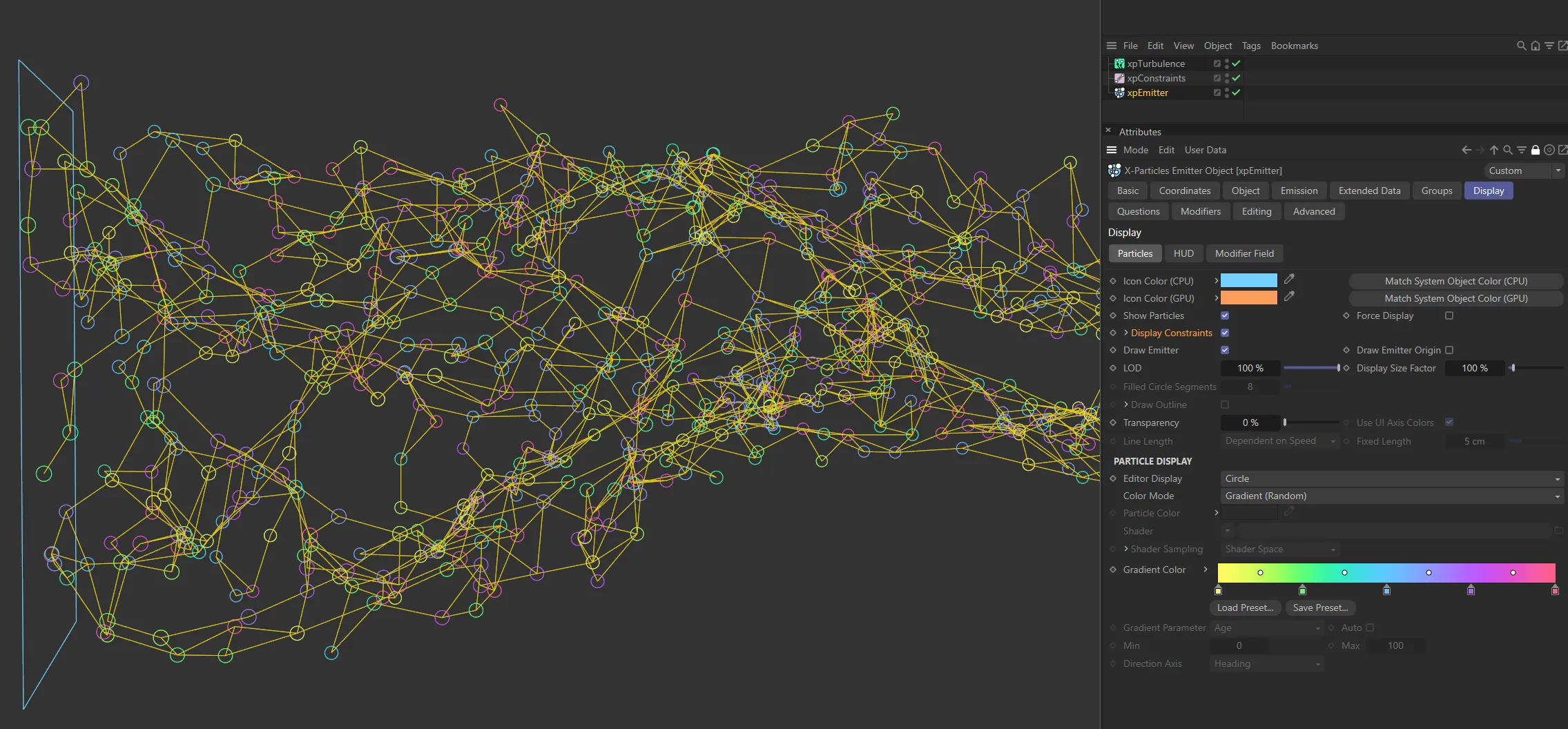
With Display Constraints enabled, it is possible to see the connections between particles, as yellow lines. The particles are in Circle mode, with their color being taken from the Gradient (Random) setting.
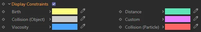
Display Constraints additional color control options.
By default all the constraints have a yellow color, but you can change that in this section.
You can also generate splines from the constraints using the xpTrail feature and render them using these colors with the X-Particles material.
Draw Emitter
Section titled “Draw Emitter”Disabling this will mean that the emitter shape will no longer be drawn in the editor.
It does not affect anything else and is not used if Emitter Shape is set to Object.
Draw Emitter Origin
Section titled “Draw Emitter Origin”If enabled, a small cross will be drawn at the centre of the emitter, plus a line pointing along the emitter’s Z-axis (this is available if Emitter Shape is set to Sphere, Object or Defined Emission).
LOD is Level of Detail.
If you are generating millions of particles, the screen redraw may become very slow, even in fast mode.
This is due to Cinema 4D’s screen handling.
You can speed up the editor redraw by reducing the LOD to less than 100%.
This will cause fewer particles than actually exist to be drawn in the editor, thereby speeding it up.
Display Size Factor
Section titled “Display Size Factor”Changing this value will alter the size of the displayed particles in the viewport.
Increasing it can be useful to visualise very small particles more easily.
This feature does not work with the Dots or Lines display types.
Filled Circle Segments
Section titled “Filled Circle Segments”If you select the Circle (Filled) display type, you can use this setting to specify the number of segments in the filled circle.
A smaller number will result in a faster editor display.
Draw Outline
Section titled “Draw Outline”Only used with the Circle (Filled) display type.
It causes an outline to be drawn around the circle.
By default this outline is a white line, but you can change it by clicking the drop-down arrow next to the Draw Outline table.
The following two additional parameters then become available.
Outline Color
Section titled “Outline Color”The color of the outline.
Outline Multiplier
Section titled “Outline Multiplier”You can alter the filled circle outline setting, which is the same shade as but slightly darker than the circle itself, with this parameter.
By default it is set to 0.8.
You can increase or decrease this value to alter the brightness of the outline.
Transparency
Section titled “Transparency”Only used if you select Sphere or Circle (Filled) as the particle type.
Use UI Axis Colors
Section titled “Use UI Axis Colors”Only used if you select Axes as the particle type.
If enabled, each axis will be drawn in the same color used in the world or object axes - normally red, green, and blue for X, Y, and Z.
If unchecked, each axis is drawn in the color specified by the Color Mode setting.
Line Length
Section titled “Line Length”Only available if Editor Display is set to Lines.
The length of the line can be controlled with this menu.
Set as Dependent on Speed, by default.
The other two options are: Dependent on Radius and Fixed.
Dependent on Speed
Section titled “Dependent on Speed”The length is calculated from the speed of the particle.
The length is the distance travelled by the particle in one frame at its current speed.
Dependent on Radius
Section titled “Dependent on Radius”The length is the same as the particle radius.
The length is a fixed value.
This value can be set in the Fixed Length setting.
Fixed Length
Section titled “Fixed Length”Only available if Editor Display is set to Lines and Line Length is set to Fixed.
This is the length of the line in Fixed mode and is not affected by the particle speed or radius.
Particle Display
Section titled “Particle Display”This is because the display parameters are controlled by the group, not the emitter.
Editor Display
Section titled “Editor Display”This is the shape of the particle in the viewport.
Set as Squares, by default.
The other choices are: Dots, Ticks, Axes, Box, Box (Filled), Spheres, Lines, Circle, Circle (Filled), Cylinder, Pyramid, Arrow, Arrow (Filled), Plane, Plane (Filled) and None.
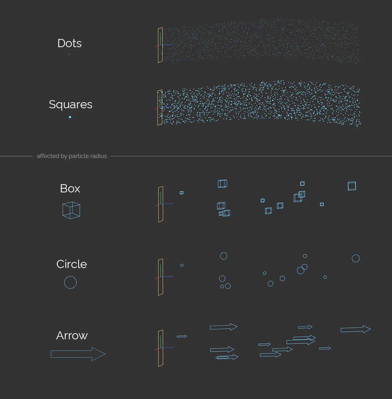
The Editor Display settings of Dots and Squares, at the top. Below, the settings of Box, Circle and Arrow each have a Variation setting on the Radius value, giving different particle sizes.
Lines will show the particles in the same way as the standard Cinema 4D emitter, drawn as short lines whose length is dependent on the particle speed.
Axes are drawn as three short lines representing the particle’s rotation axes (X, Y, and Z).
If you choose Spheres or Circle (Filled), you can also set the degree of transparency of the Sphere or Circle.
The radius of the Cylinder type is derived from the particle radius.
Its length is dependent on the particle speed.
Particle scale will also affect the length and/or radius of the Cylinder.
Choosing None will cause no particles to be drawn (they are still emitted but you can’t see them).
Color Mode
Section titled “Color Mode”Set as Single Color, by default.
The other options are: Use Emitter Icon Color, Random Color, Gradient (Random), Gradient (Parameter) and Use Shader.
Use Emitter Icon Color
Section titled “Use Emitter Icon Color”With this option, the particles will have the same color as the emitter icon.
Single Color
Section titled “Single Color”The particles all have the same color, from the Color setting.
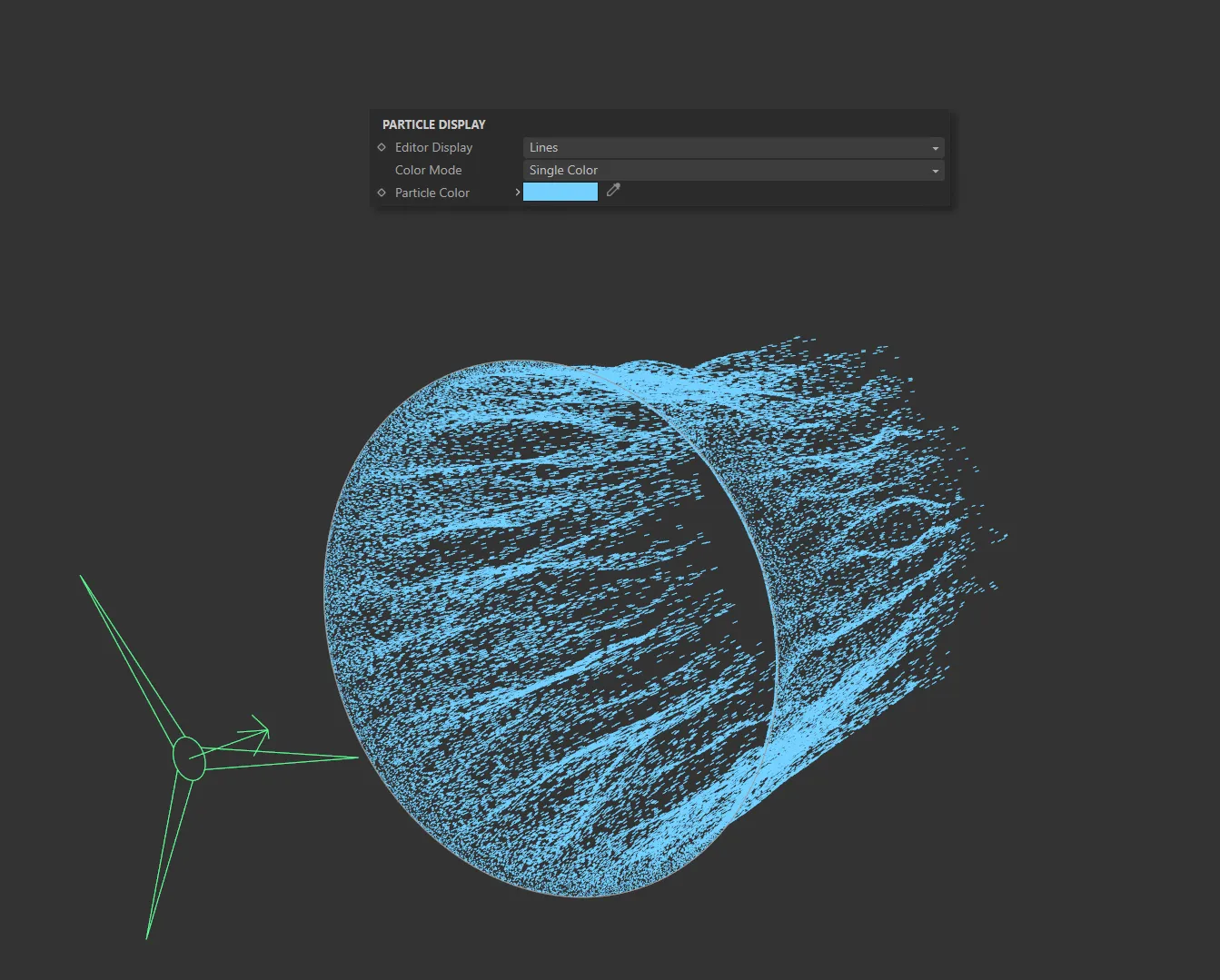
Color Mode set to Single Color, with the Particle Color being blue.
Random Color
Section titled “Random Color”Particles are assigned a randomly-chosen color.
Gradient (Random)
Section titled “Gradient (Random)”A random color is chosen for each particle from the Gradient Color gradient.
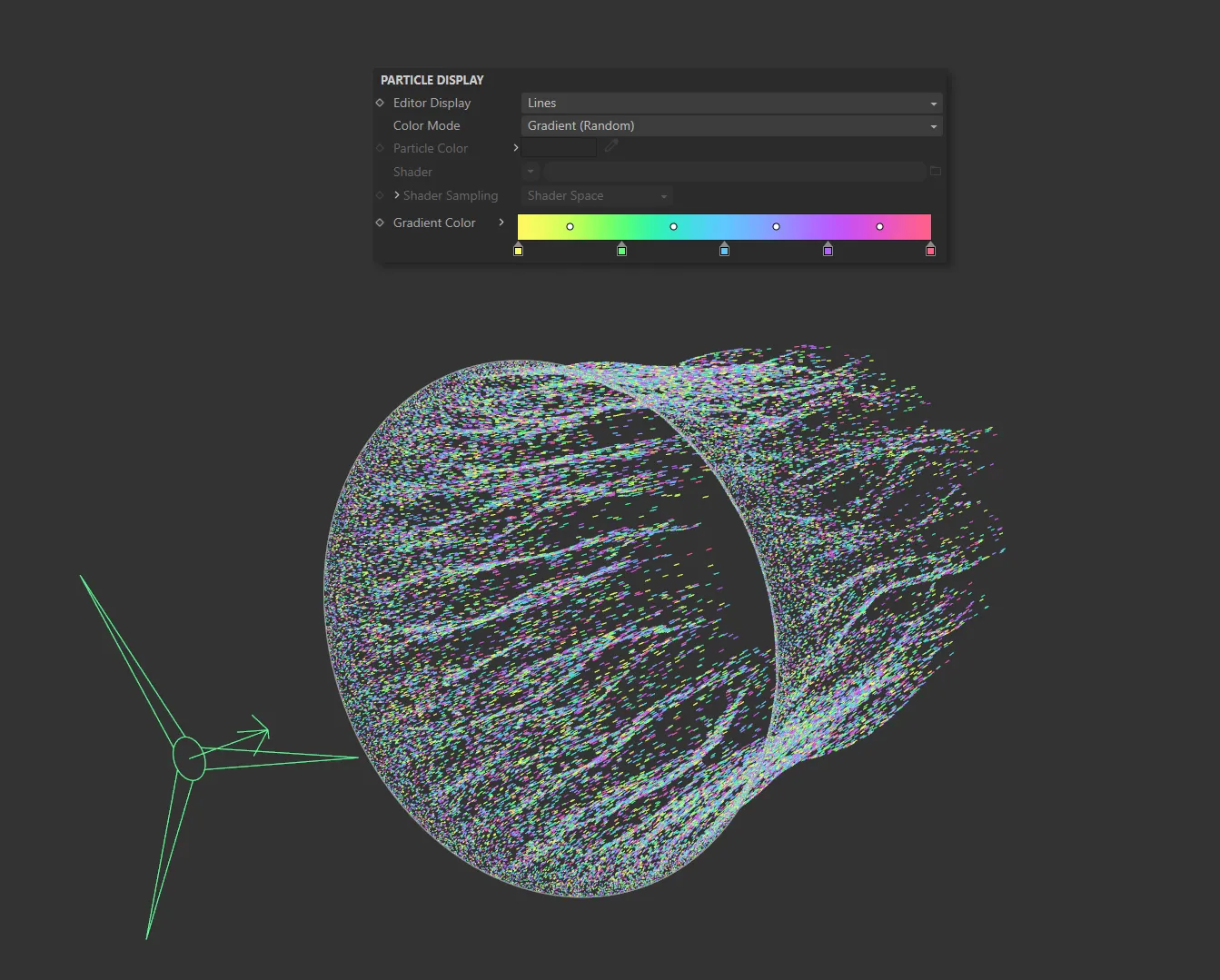
In this image, the Color Mode is set at Gradient (Random), with the particles color coming randomly from the Gradient Color setting.
Gradient (Parameter)
Section titled “Gradient (Parameter)”The particle color is chosen from the Gradient Color gradient but the color chosen is determined by the Gradient Parameter drop-down.
This means that you will not be able to change the particle color with (for example) a Color Modifier or any other method that changes the color.
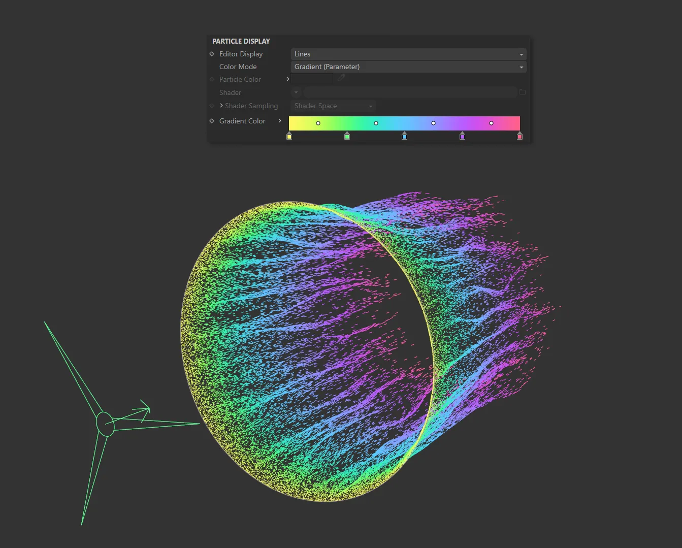
Here the Color Mode is set to Gradient (Parameter). The particles are being colored from the Gradient Color setting by their age.
Use Shader
Section titled “Use Shader”In this mode particles are colored by a shader placed into the Shader link field.
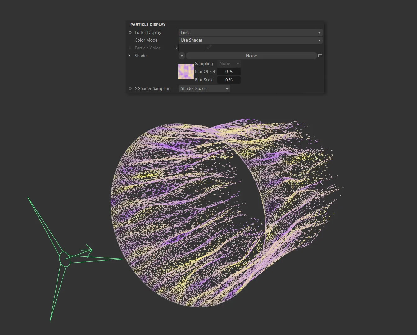
In this image, a Noise shader is coloring the particles in the Color Mode of Use Shader.
Particle Color
Section titled “Particle Color”The color of the particle in the viewport.
This is used in the editor and in the X-Particles material if that is set to use the particle color.
The default is a light green.
Shader
Section titled “Shader”A link field for the shader to use.
If Color Mode is set to Use Shader there is the option to use a shader to generate the color.
In these modes, additional parameter options become available.
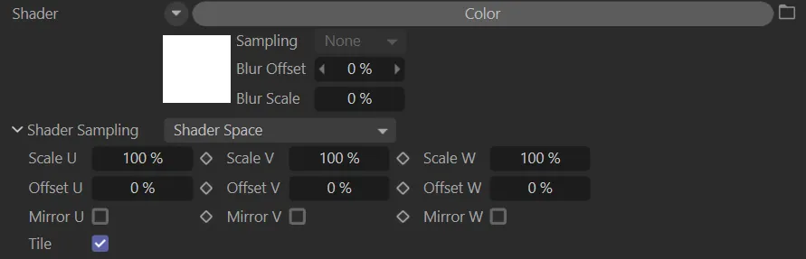
Additional Shader parameter options.
Shader Sampling
Section titled “Shader Sampling”Set as Shader Space, by default.
The alternative is Random.
Shader Space
Section titled “Shader Space”This will sample the color at the particle position in the 3D world.
Random
Section titled “Random”This will sample the shader at a different random point in each frame.
Scale U, Scale V, Scale W
Section titled “Scale U, Scale V, Scale W”These three parameters control the size of the shader across the sample space.
If the Tile parameter is checked, a bitmap will be tiled across the sample space and the number of tiles is controlled by these parameters.
If Tile is unchecked, the bitmap is simply scaled.
Offset U, Offset V, Offset W
Section titled “Offset U, Offset V, Offset W”The shader will be offset by these amounts in the respective direction.
Mirror U, Mirror V, Mirror W
Section titled “Mirror U, Mirror V, Mirror W”Checking these boxes will mirror the shader across the respective axis.
If a bitmap is used, enabling this will cause it to be tiled across the sample space.
The number of tiles is controlled by the Scale U and Scale V settings.
The parameter has no effect on procedural shaders.
Gradient Color
Section titled “Gradient Color”This is used in Gradient (Random) and Gradient (Parameter) modes.
By default, this is a blue to white gradient.
Gradient Parameter
Section titled “Gradient Parameter”If you need to alter the color during an animation you can use this option or you can use the xpColor modifier.
If you use xpColor , you must choose another color mode rather than this one or the changes made by the modifier will never be seen.
In Gradient (Parameter) mode, the color the particles are given is taken from the Gradient Color setting but the precise color is determined by the chosen setting in this drop-down.
Set as Age, by default.
The other options available are: Speed, Speed (World), Radius, Fluid Density, Fluid Density/Velocity, Granular, Fluid Surface, Mass, Temperature, Smoke, Fire, Fuel, Distance Travelled, Direction, P-P Distance and Rotation.
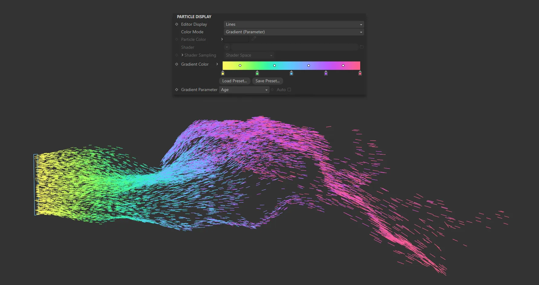
With the Gradient Parameter set to Age, particles are being colored on the color scale in the Gradient Color parameter, dependent on how many frames since they were ‘born’.
As an example, if the parameter is Age (as above), new particles are given the color from the extreme left of the gradient.
Particles at the end of their lifespan are drawn in the color from the extreme right of the gradient.
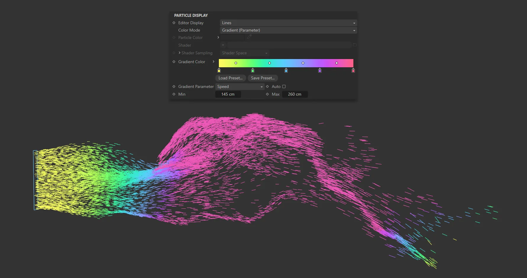
Here the Gradient Parameter is set to Speed, with the fastest traveling particles being pink and the slowest, yellow.
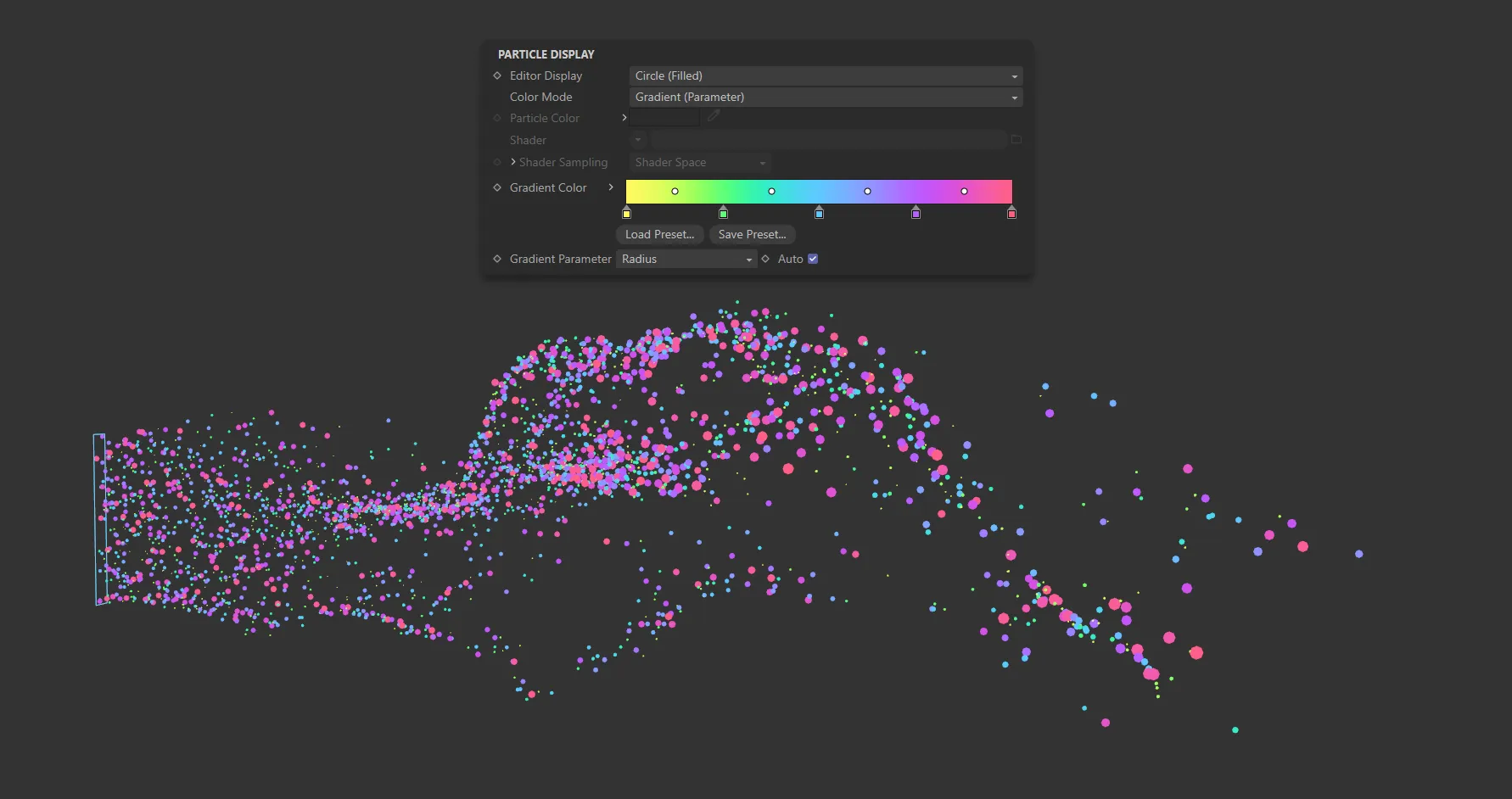
In this image, Gradient Parameter is set to Radius, with the larger particles being colored pink.
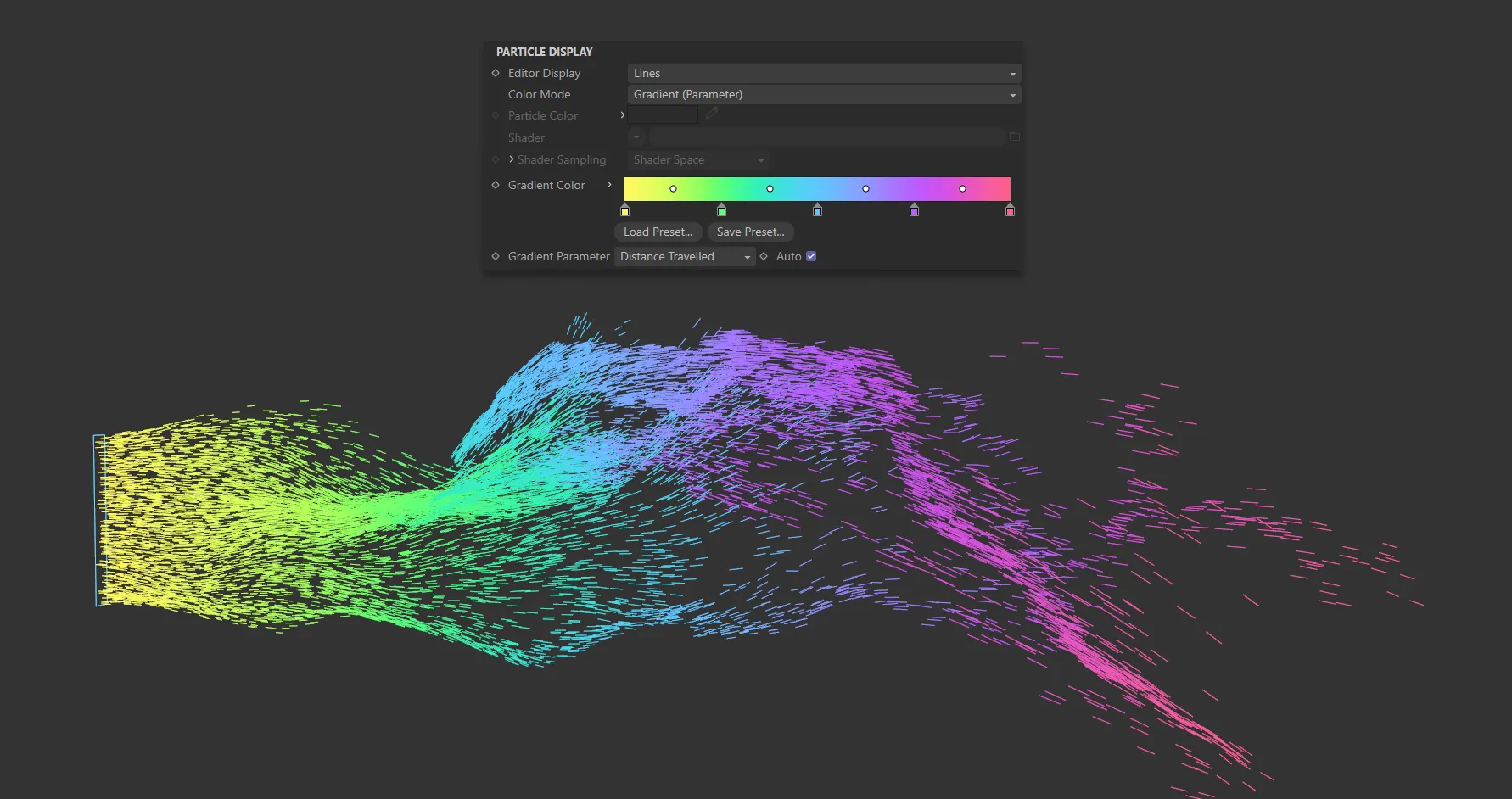
Gradient Parameter is set to Distance Traveled, with pink (on the right of the Gradient Color scale) being the furthest traveled.
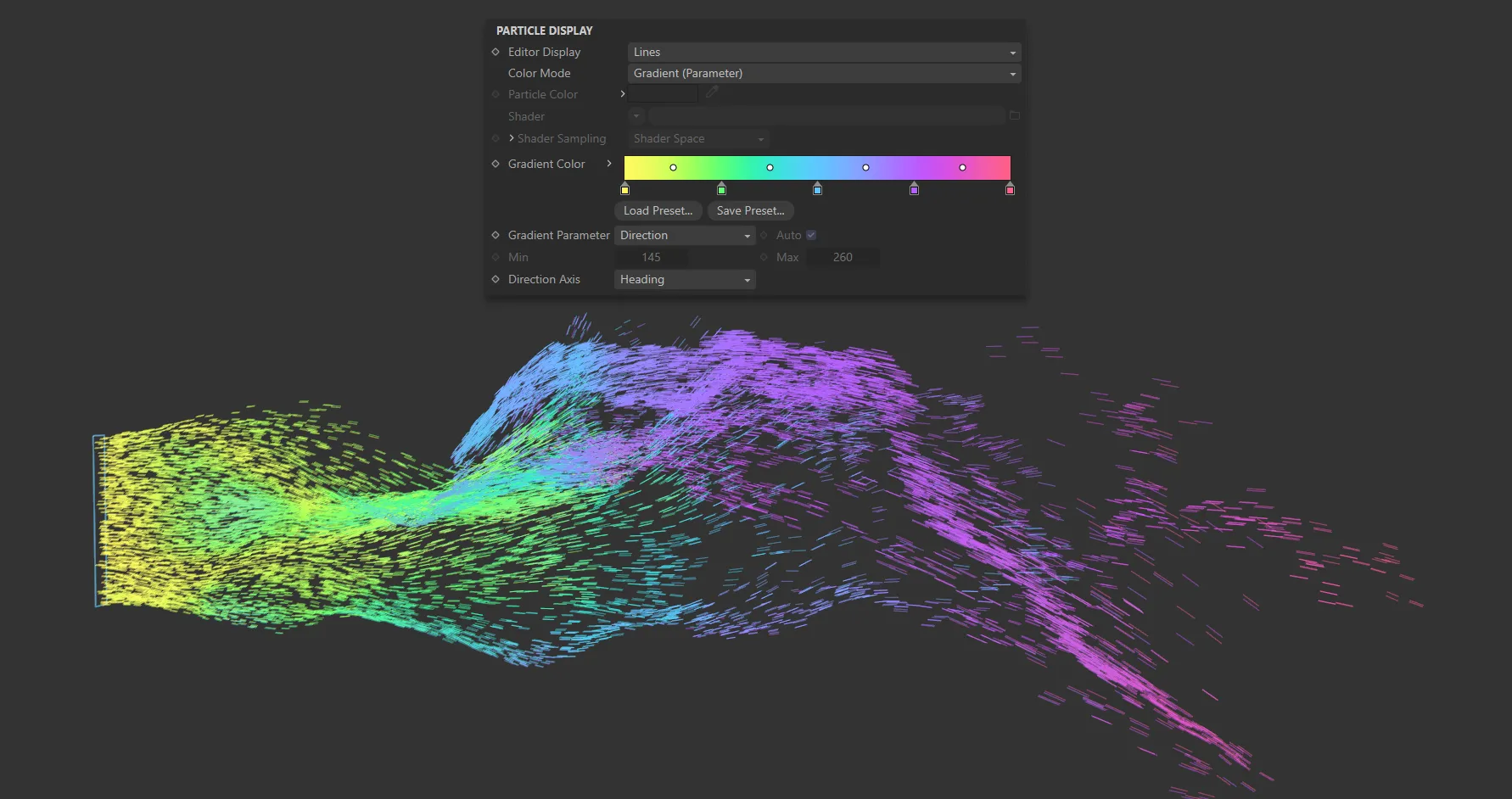
The Gradient Parameter is set to Direction here, with the Direction Axis parameter being activated and set to Heading.
Additional Notes:
To use Speed (World) you must enable World Speed in the emitter’s Extended Data tab.
Fluid Density and Fluid Density/Velocity will only work if an xpFluidFX, xpFluidPBD or nxFluids feature is active in the scene.
The values represent the amount of compression of the fluid.
Granular is a measure of the number of neighbouring particles.
To use it, xpFluidFX or nxFluids must be present and, in the emitter’s Extended Data tab, the Fluid Type must be set to Granular.
Direction is an absolute value; there is no min/max setting possible with this.
Particle direction is a vector, with three components to indicate the amount of movement along each axis.
Each component can be between 0 (zero) and 1; this is used as an index into the gradient to choose the color.
P-P Distance is the distance to the nearest particle from the one to be colored.
It will only work if Nearest Particle Data has been enabled, so that the particle holds the distance to the nearest other particle.
When enabled, the color gradient is automatically mapped to the range of values in that property.
For example, if Speed is chosen in Gradient Parameter, the slowest particles are given the color at the left edge of the gradient, while the fastest ones are given the color at the right edge.
If this is disabled, you can choose the range to map to the gradients using the Min and Max settings.
This is not available with the Direction, P-P Distance, or Rotation options.
With P-P Distance, you must set the range in the Min and Max settings.
Min, Max
Section titled “Min, Max”The minimum and maximum values to use when the Auto parameter is disabled.
These settings are also unavailable with the Direction parameter.
Direction Axis
Section titled “Direction Axis”This is used only if Gradient Parameter is set to Direction or Rotation.
The options in the menu are the individual axes, Heading, Pitch or Bank, or all three axes combined.
Direction
Section titled “Direction”When using this mode, if you select one of the individual direction axes, the emitter will select a color from the gradient using that axis alone.
For example, if Heading is selected and the particle direction has no contribution from the heading, the color from the left hand end of the gradient is used.
If its direction is solely along the positive or negative world X-axis, with no change in pitch or bank, the color from the right hand end of the gradient is used.
The same is true for the Pitch and Bank axes.
If you select HPB Combined, the final color is made up of contributions from all three axes.
The Heading takes the first one-third of the gradient, the Pitch the middle third, and the Bank the last third.
The three colors are then added together to make the final particle color.
Rotation
Section titled “Rotation”A rotation of zero degrees around the selected axis will return the color at the left edge of the gradient, while a rotation of 360 degrees will return the color from the right-hand edge of the gradient.
If you choose HPB Combined as the axis, the three individual axis values are added together and converted to the range 0 (zero) to 360 degrees.
HUD tab
Section titled “HUD tab”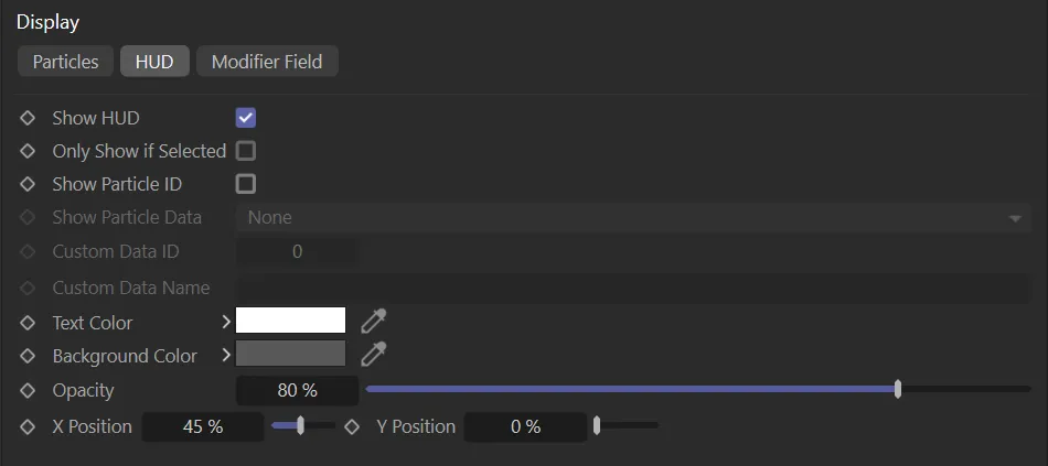
HUD tab menu.
Show HUD
Section titled “Show HUD”If enabled, shows the HUD (Head-Up Display) in the editor.
Only Show if Selected
Section titled “Only Show if Selected”If enabled, the HUD will only be shown if Show HUD is enabled and the emitter is selected in the object manager.
Show Particle ID
Section titled “Show Particle ID”If enabled, each particle will have a small label showing its unique ID number.
You can use this with Question objects which test for the particle ID.
Show Particle Data
Section titled “Show Particle Data”This drop-down menu lets you choose an item of particle data to be displayed alongside its ID.
Show Particle ID must be checked for this option to become available.
The possible data items that can be displayed are: Age (Frames), Age (Seconds), Radius, Speed, Mass, Temperature and Custom Data.
Custom Data ID, Custom Data Name
Section titled “Custom Data ID, Custom Data Name”If you choose Custom Data from the Show Particle Data drop-down, these two fields become available.
You can then enter the ID and/or the name of a custom data item.
Text Color, Background Color, Opacity
Section titled “Text Color, Background Color, Opacity”These settings allow you to change the colors used in the HUD and its opacity.
X Position, Y Position
Section titled “X Position, Y Position”These settings give the location of the HUD on the screen, expressed as percentages of the screen width and height.
You can change these to alter the HUD location.
Modifier Field tab
Section titled “Modifier Field tab”This tab enables you to display the vectors generated by Motion modifiers.
With this display option, you can see the direction imparted to the particle and the effect on particle speed.
In this animation, Show Field is enabled, to display the modifier field, before alterations are made to the Size and Resolution settings and, finally, the display Type (changed from Line to Arrow).
Some cannot do so, because of the way they work.
Those which do produce a display are as follows: xpAttractor, xpCover (but only if the particle speed changes), xpExplode (only if Set Speed at Start Only is disabled), xpFollowSurface, xpGravity, xpRotator, xpSoundDisplacement (but only when the animation is playing and only when particle velocity changes), xpSpeed, xpSplineFlow, xpStrangeAttractors, xpTurbulence, xpVortex (you must disable the Auto parameter and set the min/max values manually) and xpWind.
Other modifiers do not affect the velocity (that is, they only affect speed or direction).
This means that, with some modifiers, certain conditions must be met to show a display, i.e. the velocity must be changed, which isn’t always the case.
Show Field
Section titled “Show Field”Check this box to display the modifier field vectors.
Direction Only
Section titled “Direction Only”If this is enabled, the size of each displayed vector is identical.
The speed effect is then only shown by the color.
If this is unchecked, the length of the displayed vector will be proportionate to the effect on the speed.
Set as Line, by default, this drop-down menu controls the vector display.
The other options are: Dot and Arrow.
The vectors are displayed as either, small dots, thin lines or arrows.
Resolution
Section titled “Resolution”For every point in 3D space, there will be a vector value, but that is an infinite number of vectors and they cannot all be shown.
You can alter the number of vectors shown with this drop-down menu.
The options are: Low, Medium, High or Custom.
The default setting is Low, which is often good enough for most purposes.
Custom
Section titled “Custom”With this option you can choose your own resolution by changing the Cell Size parameter.
Cell Size
Section titled “Cell Size”Use this parameter to determine the display resolution when Resolution is set to Custom.
Min, Max
Section titled “Min, Max”These are the lower and upper limits of the display field respectively.
Also, that if the falloff area is outside the field boundary, no vectors will be shown.
The colors from this gradient are used to color the vector display according to the effect the modifier would have on particle speed.
As the speed change increases, the selected color moves towards those from the right-hand end of the gradient.
Transparency
Section titled “Transparency”You can change the transparency of the displayed vectors with this parameter.
If this is enabled, the range of possible speed changes on the particle is calculated automatically.
This gives the best spread of colors from the gradient, since the minimum calculated speed change will use the color from the left of the gradient and the maximum change uses the color from the right of the gradient.
Very importantly, the speed does not mean the particle speed.
It means the change in particle speed, which occurs due to the vector in each voxel of the grid.
If the vector does not change the speed, no vector will be displayed.
If you disable this, the range is determined manually from the Min Speed and Max Speed settings.
For example, if Min Speed is set to 50 and Max Speed is set to 150, any vector causing a speed change of 50 or less will use the color at the left-hand end of the gradient; any vector causing a speed change of 150 or more will use the color at the right-hand end of the gradient.
For example, with an xpTurbulence modifier, if you disable this and leave the Min Speed and Max Speed settings at their default values, you will see the vectors disappear.
This is because the actual changes are very small - typically in the range 0 (zero) to 3.5. So you may need to change the min/max settings quite radically to see the vectors if Auto is unchecked.
Very occasionally it may not be possible for the emitter to calculate the min/max values automatically and you will have to uncheck Auto and set these values manually.
Use Time
Section titled “Use Time”In some cases, if a modifier parameter is animated, the vectors may change from frame to frame.
If this is enabled, the vector display will be updated when the vectors change.
Since the continual redrawing of the vectors can slow down playback, unchecking this will turn the display update off.
Min Speed, Max Speed
Section titled “Min Speed, Max Speed”The minimum and maximum values to use if Auto is unchecked.
You may not always want all modifiers to be included in the final display, or perhaps you need to specify one or more modifiers to use but not the others.
You can do this by dragging modifiers into the Modifiers list.
If this drop-down menu is set to Exclude none of the modifiers in the list will be included in the display.
If the drop-down is set to Include only those modifiers in the list will be included in the display.
Modifiers
Section titled “Modifiers”The list of modifiers to include in or exclude from the vector display.
You can use this to specify exactly which modifier will be used to show the modifier vectors.
Copyright © 2026 INSYDIUM LTD. All rights reserved.