xpFollowSpline
xpFollowSpline moves a particle along a spline.
General tab
Section titled “General tab”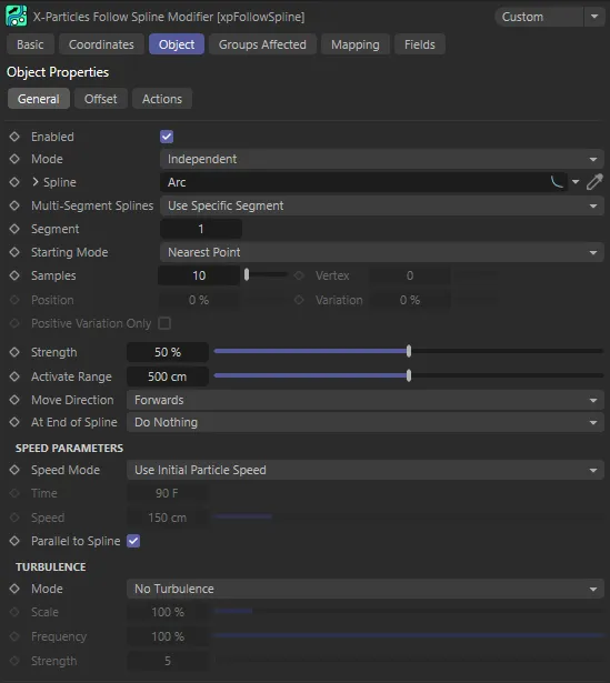
xpFollowSpline General tab menu.
Enabled
Section titled “Enabled”Checking this box activates xpFollowSpline.
Set at Independent, by default.
You can change this to Action-Controlled.
Independent Mode
Section titled “Independent Mode”In this mode, particles will be affected if they come into the field of effect of the modifier.
Action-Controlled Mode
Section titled “Action-Controlled Mode”When in the Action-Controlled Mode setting, the modifier will only act on a particle when told to do so by an action.
Spline
Section titled “Spline”This is the spline the particles will follow.
Spline primitives may be used in here as well as editable splines.
It is possible to use an X-Particles Trail object in this field.
In other words, if you have an xpTrail object in this field and the particles to be affected by the modifier are generated by the same emitter used by the xpTrail object, those particles will be ignored.
However, you can use a second emitter to follow the trails of the one which generates the trails.
Any spline dropped into this field will have its Cinema 4D Object Properties available by using the drop-down arrow.
Multi-Segment Splines
Section titled “Multi-Segment Splines”Set as Use Specific Segment, by default.
If the spline has more than one segment, you can use this drop-down to choose which segment to use.
Use Any Segment
Section titled “Use Any Segment”The modifier will randomly select from all the segments and send the particle to the chosen point on that segment.
Animation to demonstrate Multi-Segment Splines set to Use Any Segment.
Use Specific Segment
Section titled “Use Specific Segment”The modifier will use the segment you specify in the Segment field.
Here, Multi-Segment Splines is set to Use Specific Segment, with Segment 3 selected.
Use Segments in Sequence
Section titled “Use Segments in Sequence”With this option, the modifier will send each particle to different segments in sequence.
That is, if the spline has five segments, particle 1 will go to segment 1, particle 2 to segment 2, and so on.
Particle 5 would go to segment 5, then particle 6 goes to segment 1 (since there are only 5 segments, the cycle is then repeated).
You can do this, but only with separate modifiers under action control.
Use Nearest Segment
Section titled “Use Nearest Segment”In this mode the modifier will find the nearest segment of the spline to the particle and use that segment.
Segment
Section titled “Segment”This is the segment to use when Multi-Segment Splines is set to Use Specific Segment.
Starting Mode
Section titled “Starting Mode”Set at Nearest Point, by default.
When the modifier acts on a particle, the particles may initially be at some distance from the spline.
The first thing the modifier needs to do is move the particles to the spline.
This setting determines where the particles will move to before moving along the spline itself.
The other options are: Nearest Vertex, Specific Vertex and Position Along Spline.
Nearest Point
Section titled “Nearest Point”The modifier will move particles to the point on the spline which is nearest to the particle.
This is not a spline vertex, but a point in 3D space somewhere along the spline.
Nearest Vertex
Section titled “Nearest Vertex”The modifier will move particles to the vertex on the spline which is nearest to the particle.
Specific Vertex
Section titled “Specific Vertex”The modifier will move particles to the spline vertex, which is specified in the Vertex setting.
If a number is entered into Vertex which exceeds the vertex count of the spline, the modifier does nothing.
In this animation, the Starting Mode is set as Specific Vertex, with the 12th Vertex selected.
Position Along Spline
Section titled “Position Along Spline”The modifier will move particles to the point along the spline which is given in the Position setting.
If this happens, you could move the emitter slightly so that it is closer to one point on the spline than any other.
By comparison to the above, the setting here is Position Along Spline, with a Position value of 55% sending particles to the point 55% along the length of the spline, to begin following it.
Samples
Section titled “Samples”This is only available if the Nearest Point option is chosen.
To find the nearest point to the particle, the modifier checks the distance from the particle to a number of points along the spline.
If this value is low, you may see different particles moving to very different points on the spline.
You can reduce the gaps between sample points by increasing this value, but high values will slow the system down.
Vertex
Section titled “Vertex”This is the spline vertex used in the Specific Vertex setting.
Position
Section titled “Position”The position along the spline in percentage terms, used in the Position Along Spline option.
0 (zero) % is the start of the spline; 100% is the end.
Variation
Section titled “Variation”When Position Along Spline is chosen, you can add some variation to the selected location with this setting.
A value of 100% will distribute the particles along the entire spline.
Positive Variation Only
Section titled “Positive Variation Only”If you have added some variation to the starting point on the spline, the actual starting point will be somewhere either side of the chosen starting position.
For example, if the starting position is set to 0 (zero) % and the variation to 10%, the actual starting position will be somewhere between +5% and -5% along the spline.
For a closed spline, like a circle, -5% is the same as +95% along the spline.
95% of the distance along a closed spline is very close to the start of the spline, but that is often not the case for open splines.
For this reason, you can enable this option, to have only a positive variation from the starting position so that you don’t start somewhere which is not on the spline.
Strength
Section titled “Strength”This ‘acuteness of turn’ setting is only used when the particles are moving to their starting position on the spline.
A lower value results in a curved path to the starting position rather than an abrupt change of direction.
However, if this is set too low, the particle may not be able to reach its starting position on the spline.
Activate Range
Section titled “Activate Range”The modifier will start to move the particle to its starting position when its distance to the starting position is within this range.
If some or all of the particles are failing to move to the spline, you may need to increase this value.
With Activate Range set at 50cm, a particle will only move to the starting position if it is within that distance (50cm) of it.
Move Direction
Section titled “Move Direction”The direction the particles move along the spline, Forwards or Backwards.
At End of Spline
Section titled “At End of Spline”This setting determines what happens when the particle reaches the end of the spline (or if the particle is traveling backwards, when it reaches the start of the spline).
Set as Do Nothing, by default, there are three additional options: Loop, Repeat and Reverse.
Do Nothing
Section titled “Do Nothing”When the particle reaches the end the modifier will no longer affect it and the particle will continue to travel in its most recent direction.
This setting causes the particle to loop from the end point to the start point of the spline.
Here, At End of Spline is set to Loop, causing particles to loop around to the start of the spline to continue their journey.
Repeat
Section titled “Repeat”This causes the particle to leave the spline and move to a new starting position (which may be the same as its original starting position), not by traveling back along the spline but in a direct line.
It will then move along the spline as before.
This option is most useful when used with splines that are not closed but will work with closed splines too.
At End of Spline is set to Repeat, in this scene, with particles repeating from the designated start and end positions of the spline.
Reverse
Section titled “Reverse”This will cause the particle to reverse direction and travel back the way it came.
With this setting, you can set the particle to oscillate backwards and forwards along a spline.
In this animation, At End of Spline is set to Reverse. The Position setting of 70% means they only have a short journey from their start until they reverse their steps at the end point of the spline.
Speed Parameters
Section titled “Speed Parameters”Speed Mode
Section titled “Speed Mode”Set as Use Initial Particle Speed, by default.
The speed mode chosen has a significant effect on particle movement around the spline.
The alternatives are: Use Current Particle Speed, Complete Length in Time and Set Speed.
Use Initial Particle Speed
Section titled “Use Initial Particle Speed”The particle will travel around the spline with the speed it has when it starts to follow the spline and will remain fixed from then on.
With this option, the speed cannot be changed by other modifiers but can be altered using data mapping.
Use Current Particle Speed
Section titled “Use Current Particle Speed”The particle will travel around the spline with its current speed.
With this option, the speed can be changed by other modifiers but cannot be changed using data mapping in this modifier.
Complete Length in Time
Section titled “Complete Length in Time”With this setting, the particle may speed up or slow down so that the particle would travel along the complete length of the spline by the value in the Time setting.
With this option, the speed cannot be changed by other modifiers but can be altered using data mapping.
Set Speed
Section titled “Set Speed”The modifier will set the particle speed to the value found in the Speed parameter.
It cannot be changed from then on, except by data mapping.
The time to move along the length of the spline, when Speed Mode is set to Complete Length in Time.
The value to use when Speed Mode is set to Set Speed.
Parallel to Spline
Section titled “Parallel to Spline”If this box is checked, the speed of the particle will be adjusted to ensure it remains parallel to the spline being followed.
Some particles may speed up a little and some will slow down, depending on their relative position to the spline.
When enabled, it gives the smoothest movement of the particles along the spline.
When disabled, you may see jitter in the particle’s movement, which is especially noticeable if you are using an xpTrail object.
However, if you want to alter the particle speed using another modifier, such as an xpTurbulence modifier, you can untick this box, as otherwise you may see little effect from the other modifier.
Turbulence
Section titled “Turbulence”These settings allow you to add some chaotic movement to the particles as they move along the spline.
Set as No Turbulence, by default, this controls how turbulence affects particle movement.
The other options are: Affect Offset, Affect Velocity and Affect Both.
No Turbulence
Section titled “No Turbulence”The default setting.
No turbulence is applied to the particles.
Affect Offset
Section titled “Affect Offset”The turbulence affects the offset from the spline but not its movement along the spline.
Animation to demonstrate the effect of the Mode setting, Affect Onset.
Affect Velocity
Section titled “Affect Velocity”The turbulence affects the speed and direction of movement along the spline but does not directly affect the offset.
By comparison, this animation shows the setting of Affect Velocity.
Affect Both
Section titled “Affect Both”Both offset and velocity are affected.
Finally, this scene has the Affect Both setting, with a combination of the first two options.
Scale,
Section titled “Scale,”This alters the underlying turbulence which is applied to the movement.
Larger scales tend to damp down the movement of the particle, giving smoother movement.
By contrast a smaller scale will produce more chaotic movement.
Frequency
Section titled “Frequency”Changes the frequency of the internal noise generator used by the modifier; the higher the value, the more rapidly the noise changes.
Strength
Section titled “Strength”The higher this value, the more chaotic the movement.
Offset tab
Section titled “Offset tab”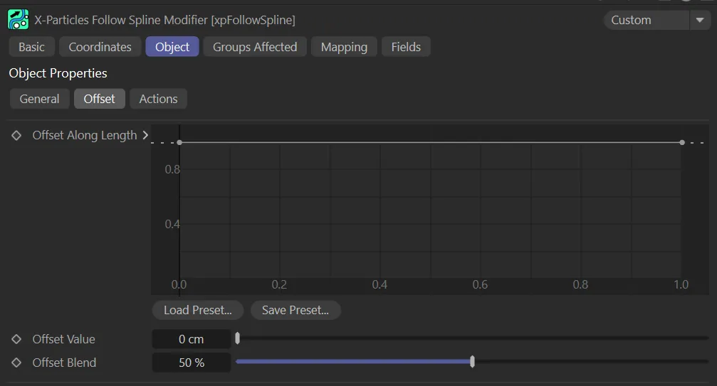
xpFollowSpline Offset tab menu.
Offset Along Length
Section titled “Offset Along Length”This spline control alters the particle offset along the spline length.
This is a percentage value, so 100% gives a maximum offset (from the Offset Value setting) and 0 (zero) % is no offset at all.
The leftmost point on the spline control gives the offset at the start of the spline and the rightmost point the offset at the end of the spline.
The Offset Value of 200cm, means that particles are offset 200cm from the base spline, in this animation. The Offset Along Length spline curve setting is designed so that the offset increases towards the halfway point of the base spline. Particles therefore become more offset as they travel along the spline, then compress back towards the center when they reach the start.
Offset Value
Section titled “Offset Value”The maximum offset from the spline.
The actual offset will be somewhere between zero and this value.
Offset Blend
Section titled “Offset Blend”This setting controls how the object is offset from the spline along the spline axes.
When set to 50% (the default) the particles are offset in all directions around the spline.
If it is set to 0 (zero) %, the offset is only along one axis (which one depends on the orientation of the spline axis); if it is set to 100% offset is along a different axis.
In both cases, the particle stream will appear to be flattened rather than forming a tube around the spline.
Actions tab
Section titled “Actions tab”You can drag any actions into this list and they will be executed when the particle is first captured by a spline or it reaches the end of its travel along the spline.
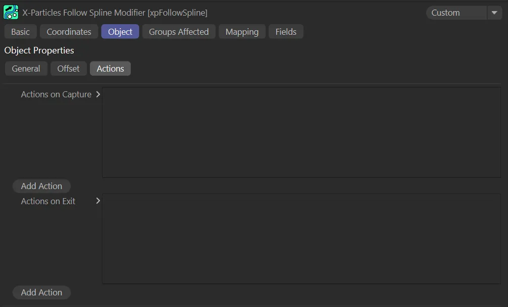
xpFollowSpline Actions tab menu.
Actions on Capture, Actions on Exit
Section titled “Actions on Capture, Actions on Exit”The lists of actions to be carried out at the start and end of travel along the spline.
Add Action
Section titled “Add Action”Clicking either button will add an action to the scene and drop it into the relevant action list.
Groups Affected tab
Section titled “Groups Affected tab”Groups
Section titled “Groups”To specify the group, drag and drop the desired Group object into this field.
This setting is useful if you want to ensure that the spawned particles are, or are not, affected by xpFollowSpline.
Mapping tab
Section titled “Mapping tab”The modifier’s settings can be mapped to particle data.
Use the dedicated manual page, below, for instructions on how this works.
Fields tab
Section titled “Fields tab”You can use the Fields options to control where xpFollowSpline operates.
Copyright © 2026 INSYDIUM LTD. All rights reserved.