xpSound
The xpSound modifier is slightly different to most other modifiers in that it can do two things.
It can change the emitter to influence emission rate and change particle parameters when they are first created.
It can also change particles during the course of the animation as with any other modifier.
General tab
Section titled “General tab”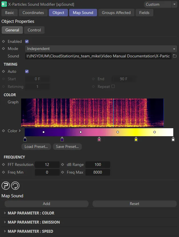
xpSound General tab menu.
Enabled
Section titled “Enabled”Checking this box enables the xpSound modifier.
Set at Independent by default.
You can change this to Action-Controlled.
Independent Mode
Section titled “Independent Mode”In this mode, particles will be affected if they come into the field of effect of the modifier.
Action-Controlled Mode
Section titled “Action-Controlled Mode”When in the Action-Controlled Mode setting, the modifier will only act on a particle when told to do so by an action.
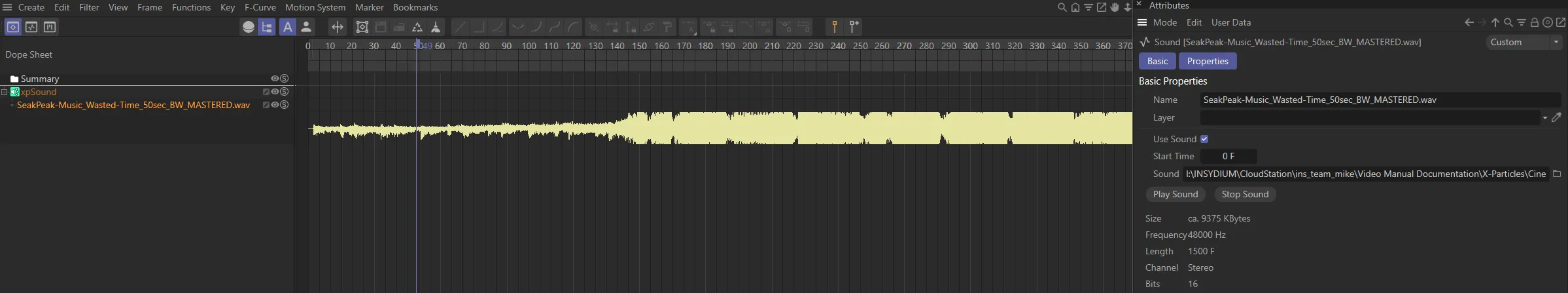
The sound file to use.
Click the button with three dots to load a sound file, which must be in .wav format.
To play the sound, you must add a sound track to the C4D timeline window.
From the Timeline, click Create, then Add Special Tracks, then scroll down to Sound.
Adding a special track, via the C4D Timeline’s Create tab.
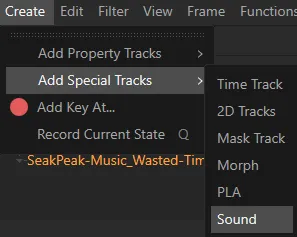
The C4D menu to access a sound track.
Further details are contained in the C4D reference documentation.
Timing
Section titled “Timing”Enabled, by default, the modifier uses the sound in time with the scene timeline.
Auto must be disabled for the following settings to become available.
Start, End
Section titled “Start, End”These are time values which control when, on the scene timeline, the audio is mapped to the particles. For example, if Start is zero and End is three seconds, the audio file will play for three seconds and then stop.
Retiming
Section titled “Retiming”This enables the audio’s timing to be changed.
For example, if Start is zero and End is three seconds, with Retiming at the default value of 1, the audio file will play for three seconds and then stop.
If Retiming is increased to 2, the audio file will still only play for three seconds, but it will play twice as fast.
Repeat
Section titled “Repeat”Checking this box will loop the sound file.
The graph is a representation of the complete sound file.
It is a graph of frequency intensity (on the vertical, or Y axis) over time (on the horizontal, or X axis).
The frequency ranges from the minimum frequency at the bottom (i.e. bass frequencies) to the maximum frequency at the top.
This range (minimum to maximum) can be changed by adjusting the Freq Min and Freq Max settings.
The cyan vertical line on the graph is the current time in the sound file.
This is the color gradient used for the graph.
It is only used for the graph color, so you can change it to anything you like without affecting the output.
The color used depends on the intensity (amplitude) of each frequency, low amplitudes using the color on the left of the gradient and high amplitudes the colors to the right.
Frequency
Section titled “Frequency”This section controls how the frequencies in the sound are analysed.
It uses a process called Fast Fourier Transform (FFT) to do this.
FFT Resolution
Section titled “FFT Resolution”This controls how many discrete chunks (FFT bins) the frequency range is split into.
Lower values give a coarser result. Increasing the value will impact on calculation time.
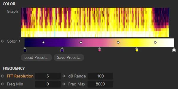
FFT Resolution value set at 5.
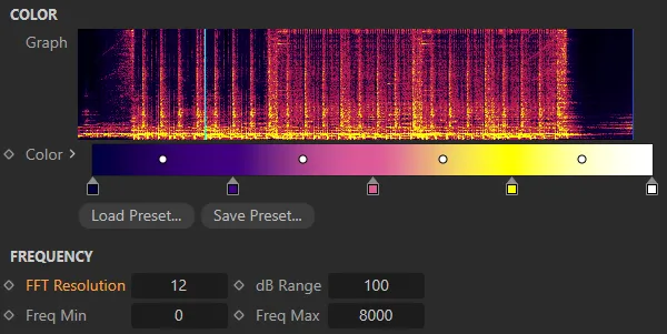
Here, the FFT Resolution is raised to 12.
dB Range
Section titled “dB Range”The audio intensity is converted into decibels (dB).
Reducing this value will start to remove low-amplitude sound and you will see the colors in the graph move towards the left hand side of the gradient.
Lower it too much and the frequency graph may become almost black (with the default colors) and the modifier will have little or no effect.
If you increase this value, more low amplitude sound is used and the effect is greater.
Freq Min, Freq Max
Section titled “Freq Min, Freq Max”These values control the frequency range used.
Increasing Freq Min will cut out lower frequencies; increasing Freq Max will bring in higher ones.
Whether you need to change these values will depend on the nature of the sound file.
Control tab
Section titled “Control tab”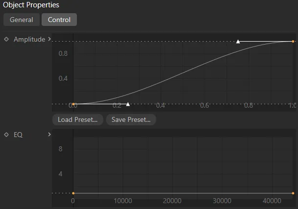
xpSound Control tab menu.
Amplitude
Section titled “Amplitude”This spline control enables you to map the amplitude values returned from the FFT; acting like an audio filter.
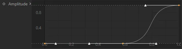
Amplitude spline control.
This is the same as the Amplitude spline but for frequencies rather than amplitude.
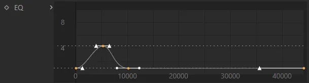
EQ spline control.
Map Sound tab
Section titled “Map Sound tab”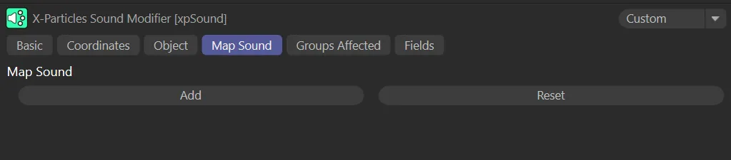
xpSound Map Sound tab menu.
This tab is initially empty, but you can map various particle data items to the sound parameters.
Click this button to add a map.
This will reveal the following additional parameters.
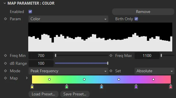
Map Sound tab, additional parameters with a Param setting of Color.
The default gradient map is shown above.
This is only available when mapping particle color.
For all other parameters, a curve control is used.
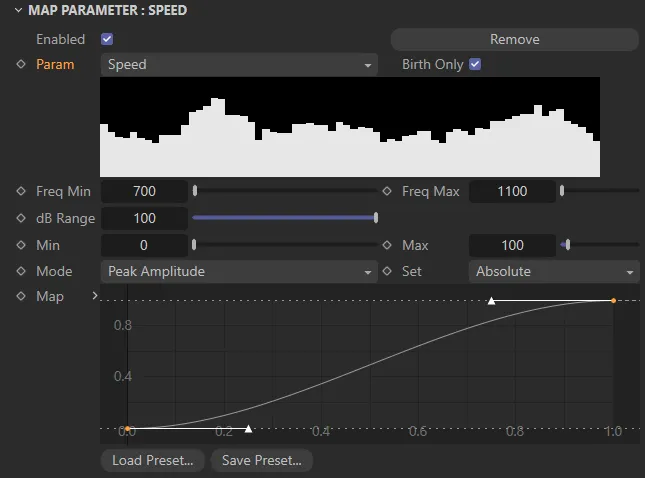
Map Sound tab, additional parameters with a Param setting of Speed.
Click this button to remove all maps.
You will be asked to confirm this before the maps are deleted.
Enabled
Section titled “Enabled”Uncheck this box to disable the map.
This is convenient for testing combinations of maps, since you can then turn maps on and off to see what difference they make.
Remove
Section titled “Remove”Click this button to remove this map (but leave all others intact).
Set as Color, by default.
This is the particle or emitter parameter to map.
The additional options are shown below.
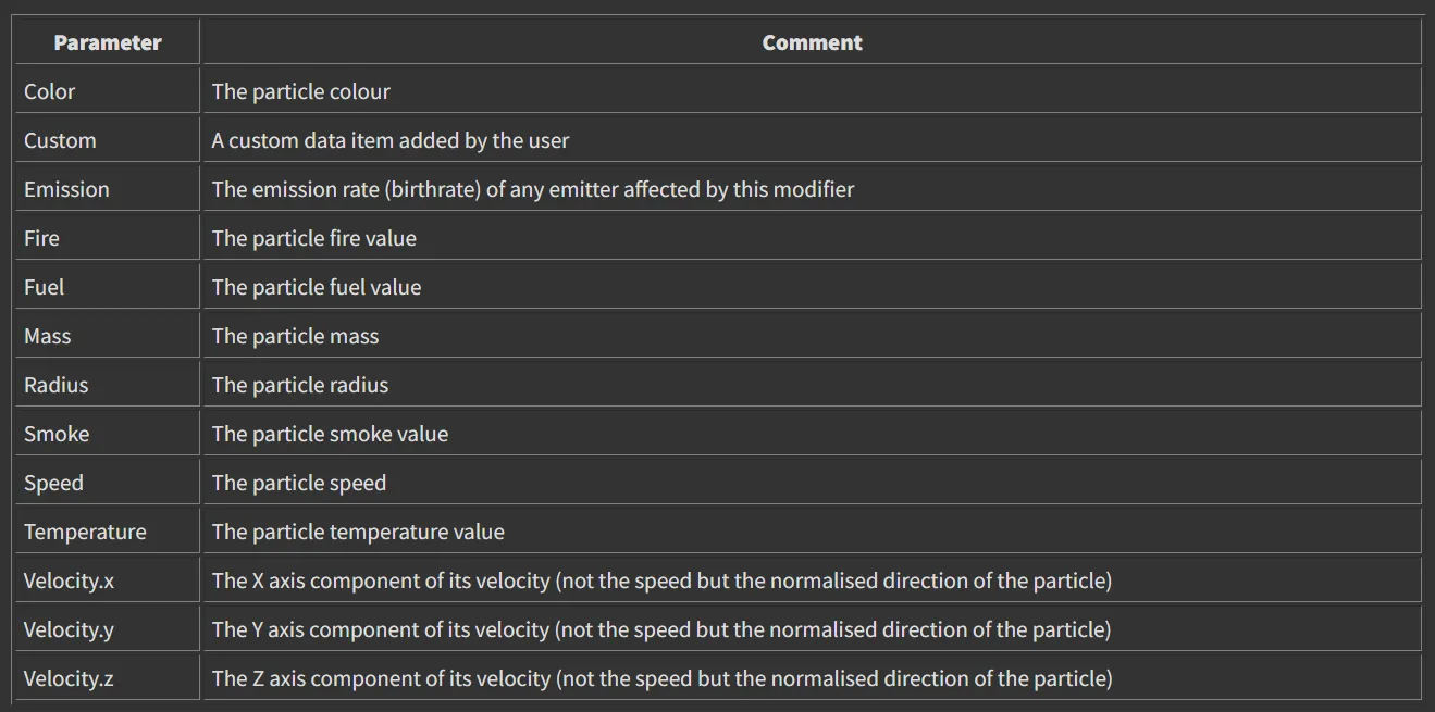
Param option settings.
Birth Only
Section titled “Birth Only”If enabled, the particle parameters will only be set when they are first created.
If it is unchecked, the parameters will also be changed during playback, as with most other modifiers.
This is not available if Param is set to Emission.
Freq Min, Freq Max
Section titled “Freq Min, Freq Max”When using Mode set to Peak Frequency (or to Combined for Color maps only), this is the frequency range used to map the parameter.
dB Range
Section titled “dB Range”This is the same as for the Freq Min and Freq Max settings, but for use when Mode is set to Peak Amplitude (or to Combined for Color maps only).
It is the range of amplitudes used to map the parameter to the color gradient or spline.
The minimum value is always zero so, if this setting has a value of 70, the actual range is 0 to 70.
If the peak amplitude in the sound file during playback is zero, the particle parameter will be mapped to the left-hand end of the color gradient or the leftmost point in the control spline.
If the peak amplitude reaches or exceeds the value in this setting, the particle parameter will be mapped to the right-hand end of the color gradient or the rightmost point in the control spline.
Set to Peak Amplitude, by default, this is the mapping mode to use.
The other options are: Combined and Peak Frequency.
Combined
Section titled “Combined”This uses a combination of the other two options.
It is only available for Color maps.
Peak Amplitude
Section titled “Peak Amplitude”The particle parameter (e.g. color, speed, etc.) depends on the peak amplitude in the sound file at the time of playback.
The range of amplitudes used is controlled by the dB Range setting.
Peak Frequency
Section titled “Peak Frequency”The particle parameter (e.g. color, speed, etc.) depends on the peak frequency in the sound file at the time of playback.
The range of frequencies used is controlled by the Freq Min and Freq Max settings.
There are four options, which determine how the calculated mapped value is used: Absolute (the default), Add, Multiply and Subtract.
Absolute
Section titled “Absolute”The calculated value is used without further change.
The calculated value is added to the current parameter value.
Multiply
Section titled “Multiply”The calculated value is multiplied by the current parameter value.
Subtract
Section titled “Subtract”The calculated value is subtracted from the current parameter value.
This can be either a color gradient, which is only available in Color maps (the particle color will be mapped to this gradient) or a spline control used for all other map types (the particle parameter will be mapped to the range specified by the Min and Max values using this spline).
Min, Max
Section titled “Min, Max”These settings are not available in Color maps.
For all others, they represent the range of mapped values for the selected parameter.
For example, if Speed is the mapped parameter, the particle speed will be set to somewhere between these values.
The actual value which is set depends on the mapping mode and the selected range for amplitude and/or frequency.
The nature of the value will clearly vary depending on the mapped parameter.
In an Emission map this represents the particle birth-rate of an emitter.
For a Radius map, it is the particle radius.
These values will therefore need to be changed, depending on the parameter being mapped.
Only available in Custom maps.
This is a name you can give to your custom data item.
Groups Affected tab
Section titled “Groups Affected tab”Groups
Section titled “Groups”To specify the group, drag and drop the desired Group object into this field.
This setting is useful if you want to ensure that the spawned particles are, or are not, affected by xpSound.
Fields tab
Section titled “Fields tab”You can use the Fields options to control where xpSound operates.
Copyright © 2026 INSYDIUM LTD. All rights reserved.