tfGrid
tfGrid adds a grid operator, with adjustment handles, to your terrain; with these, you can adapt and manipulate the landscape, including a grid brush to smooth, elevate, paint and sculpt the land.
tfGrid also offers a Control Grid Source setting (the grid you’re manipulating with tfBrush) as a custom operator output map. This means that the control grid can directly be rendered using the operator shader and inspected in the Preview tab, and the Grid Monitor.
Once activated, the tfGrid needs to be made a child of the terrain to operate.
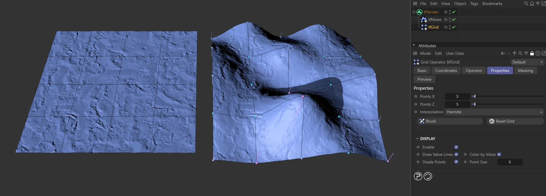
A 5x5 grid with points visible.
Properties tab
Section titled “Properties tab”The grid generates points and each of the blue points can be clicked and dragged up or down inside the viewport to create deformation.
Once the points have been moved, they leave value lines, which indicate how far they have been deformed from their default state.
The deformed points also change color.
The most deformed lines and points turn pink, with those in between being a lilac color.
Points X
Section titled “Points X”Determines the number of points on the X-axis.
Fewer points will create more deformation in the grid.
Conversely, more points will allow for more detailed distortion of the terrain.
Points Z
Section titled “Points Z”Determines the number of Points on the Z-axis.
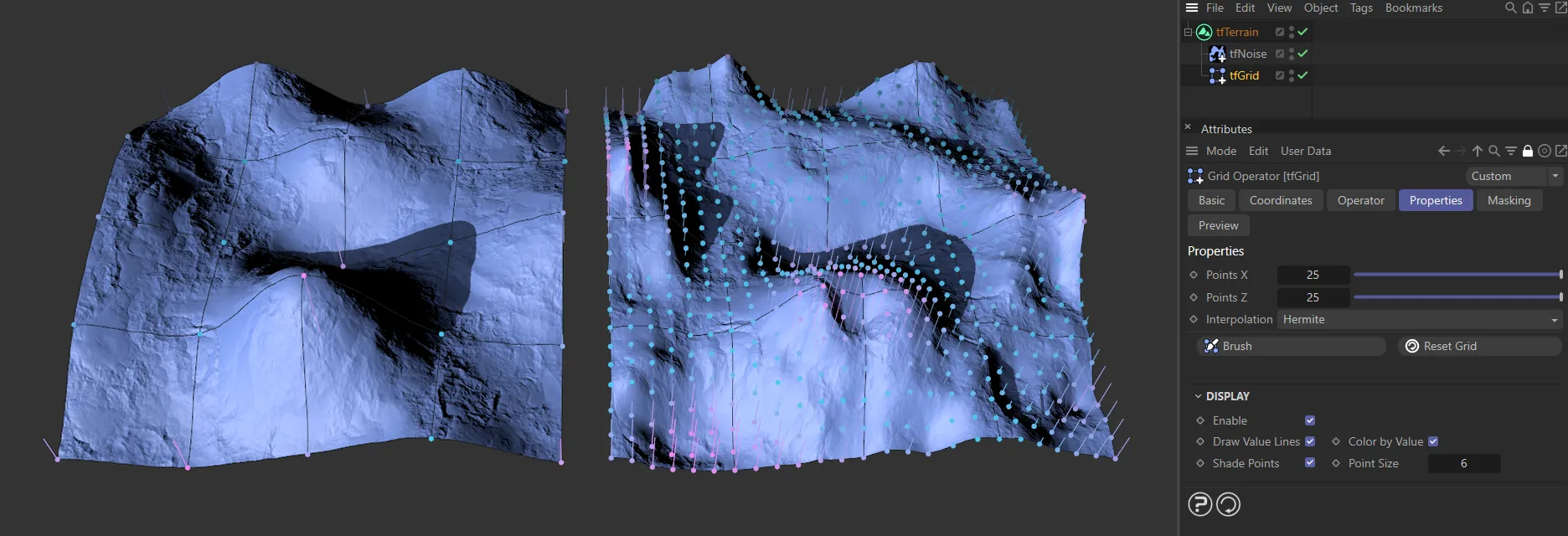
The tfGrid on the left has the default setting of 5 x 5 points. On the right, this has been increased to 25 x 25 points.
Interpolation
Section titled “Interpolation”Set at Hermite, by default.
The other options are: Nearest, Bilinear, Cosine and Bicubic.
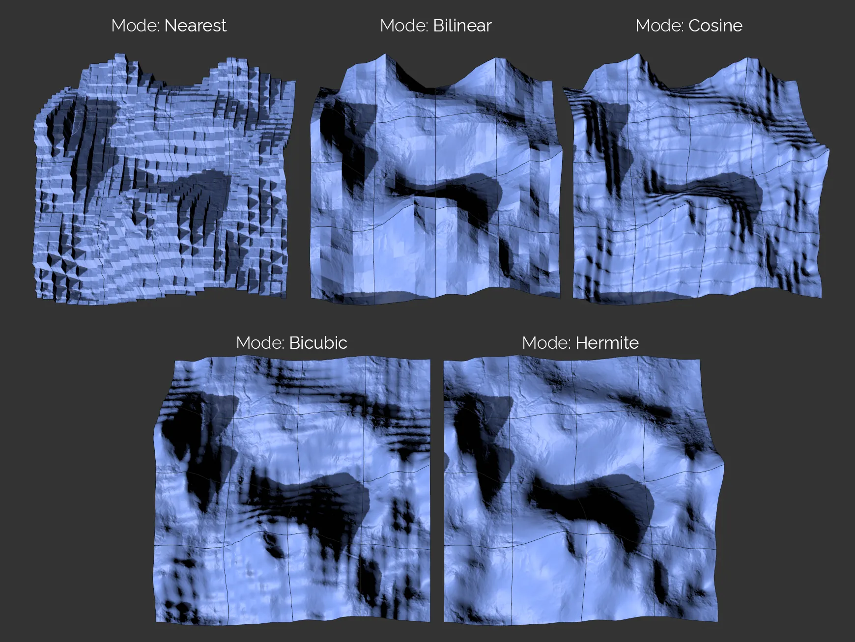
The five Interpolation settings available.
Nearest
Section titled “Nearest”Gives a ‘blocky’ look, with no interpolation at all, as shown above.
Bilinear
Section titled “Bilinear”The Bilinear setting is smooth between points, but gives hard edges.
Cosine
Section titled “Cosine”Cosine interpolation creates a smooth result, even on steps, flattening the slope on grid points.
Bicubic
Section titled “Bicubic”Similar to Cosine, this setting gives smooth deformation in the grid.
Hermite
Section titled “Hermite”This is very smooth, detailed and high quality, but rendering is slightly slower than the other modes.
Clicking on this button takes you into the tfBrush tool, with its own settings (covered in depth in its own page).
Here you can ‘paint’ in the deformation intuitively, inside the viewport.
Clicking and dragging will create a deformation of points based on the Falloff curve.
Animation to demonstrate the effect of the tfBrush feature.
Options
Section titled “Options”Radius
Section titled “Radius”This slider increases and decreases the radius of the brush.
The radius can also be adjusted by holding down the middle button on your mouse and dragging horizontally.
This animation shows the effect of the Radius slider with tfBrush.
Strength
Section titled “Strength”Set at 50%, by default, this can be reduced, to give a lighter touch, or increased, to give a heavier touch to the deformation.
The strength can also be adjusted by holding down the middle button on your mouse and dragging vertically.
In this animation, the Strength slider is being demonstrated, elevating the terrain.
Airbrush Mode
Section titled “Airbrush Mode”Depending on how you access tfBrush, the default setting will be Elevate in tfGrid or Brush in tfWarp.
The other settings in tfGrid are: Off, Smooth, Set and Transfer.
Off mode
Section titled “Off mode”This gives you a very responsive and precise deformation control.
Animation demonstrating the control with Airbrush Mode set as Off.
Elevate mode
Section titled “Elevate mode”Holding the left mouse button and moving the tool over the terrain will elevate the grid points within the tool radius.
The longer you hold down the mouse, the more elevation you will get.
Holding CTRL will negate the tool strength, inverting the effect, hence lowering the points.
Holding SHIFT will temporarily switch to Smooth mode.
Holding SHIFT and CTRL will temporarily switch to Smooth mode and negate the tool strength, making it a ‘contrast’ tool.
In this animation, the Airbrush Mode is set to Elevate, demonstrating the different controls.
Elevate Random Strength
Section titled “Elevate Random Strength”Only available in the Elevate mode, this will apply a noise to the grid points, giving some natural variation.
The noise pattern will change with every brush stroke.
Intensity
Section titled “Intensity”Increases or decreases the intensity of the Random Strength settings.
Increases or decreases the scale of the Random Strength settings.
Animation to illustrate the Random Strength settings of Scale and Intensity.
Smooth mode
Section titled “Smooth mode”The tool will gradually and gently smooth out the terrain within the tool radius, by blending the current height with the average height of all points currently within the tool radius.
The longer you hold down the mouse, the more the points will be smoothed to an average deformation elevation based on the points within the grid brush.
Holding CTRL will negate the tool strength, inverting the effect, hence increasing local contrast between mountains and valleys.
Holding SHIFT will temporarily switch to Elevate mode.
Holding SHIFT and CTRL will temporarily switch to Elevate mode and negate the tool strength, making it a ‘lower’ tool.
This animation shows the effect of Airbrush Mode set to Smooth.
Set mode
Section titled “Set mode”In Set mode, tfBrush will blend the control grid points between their current altitude and a precise altitude that can be set in tfBrush’s attributes to manually create plateaus, terraces and plains.
Holding SHIFT will temporarily switch to Transfer mode and apply the average altitude of the points within tool range at the time of starting the brush stroke.
Animation to demonstrate the Airbrush Mode of Set.
Transfer mode
Section titled “Transfer mode”In Transfer mode, tfBrush behaves almost like in Set mode, but instead of applying the altitude set in tfBrush’s attributes, it will use the average altitude of the points within tool range at the time of starting the brush stroke.
This makes it possible to click on any area of the terrain and propagate that altitude to other areas, matching their altitude with the one from the brush stroke’s starting point.
Holding SHIFT will temporarily switch to Set mode and apply the altitude set in tfBrush’s attributes.
This animation illustrates the slightly different effect of Transfer as the Airbrush Mode.
Surface
Section titled “Surface”By default, tfBrush will use all tfGrid points that are within the tool range in screen space.
This can result in distortions if the user paints while looking at the terrain at a flat angle.
If the Surface option is activated, tfBrush will instead use the points that are within tool range in 3D space.
This frees the tool from being dependent on the view angle and it will change the mouse cursor display to a 3D sphere.
The final animation shows the Airbrush Mode set to Elevate. By activating the Surface option, the painting is elevated from 2D into 3D space.
Set Altitude
Section titled “Set Altitude”Only available in the Set and Transfer modes, this parameter sets the altitude level, as explained above.
Use Falloff
Section titled “Use Falloff”This is on, as the default setting.
Falloff
Section titled “Falloff”The Falloff curve determines the effect on the elevation patterns.
This will be further amplified by the deformation settings you have chosen.
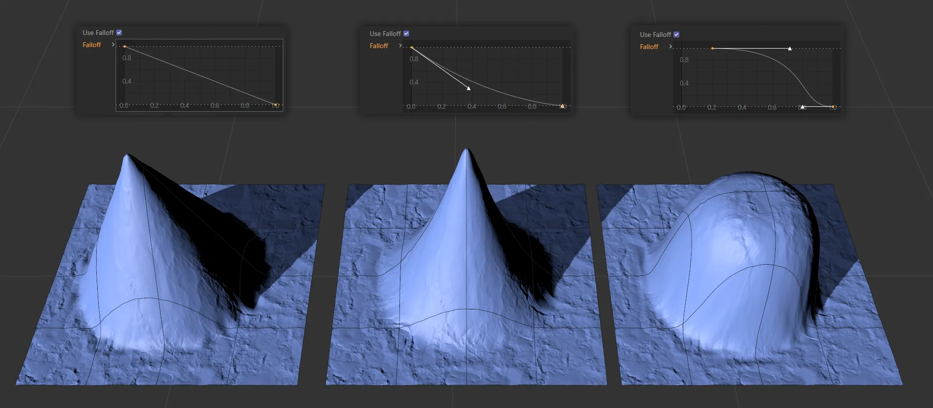
Here, there are three terrains being driven by the Falloff curve settings, above. The first, a linear curve, giving an even deformation; in the center, the default curve; finally an exaggerated bell curve, which results in a flatter hill top and steep decline to the ground.
Load Preset
Section titled “Load Preset”There are various preset falloff shapes available to load in from here.
Save Preset
Section titled “Save Preset”It is possible to save your custom falloff shapes for future use.
Auto-skip slow Operators
Section titled “Auto-skip slow Operators”The Auto-skip slow Operators option will temporarily deactivate successive operator objects that calculate too slowly.
This results in a (temporarily) less truthful viewport display, but it tremendously increases performance while making a brushstroke.
Reset Grid
Section titled “Reset Grid”Resets the grid to the default setting, so that all the points are at 0 (zero) cm.
Display
Section titled “Display”Enable
Section titled “Enable”Enabled, by default, displays the visual indicators in the grid, but they can be switched off.
Draw Value Lines
Section titled “Draw Value Lines”The value lines are on by default, but can be switched off.
Color by Value
Section titled “Color by Value”The color settings for the points (blue, lilac and pink) are on by default.
Once the points have been moved, they leave value lines, which indicate how far they have been deformed from their default state.
The deformed points also change color.
The most deformed lines and points turn pink, with those in between being a lilac color.
Switching this off will turn all the points yellow and the value lines will become green.
Shade Points
Section titled “Shade Points”Points are shaded by distance to the camera, making it easier to understand the control grid topology at a glance.
The nearest points are light blue, getting darker as they are further away.
Point Size
Section titled “Point Size”You can increase or decrease the point sizes.
Control Grid
Section titled “Control Grid”The Control Grid selection is accessed through the Preview tab, as a Source option.
As a height map, it has no interpolation between the control points.
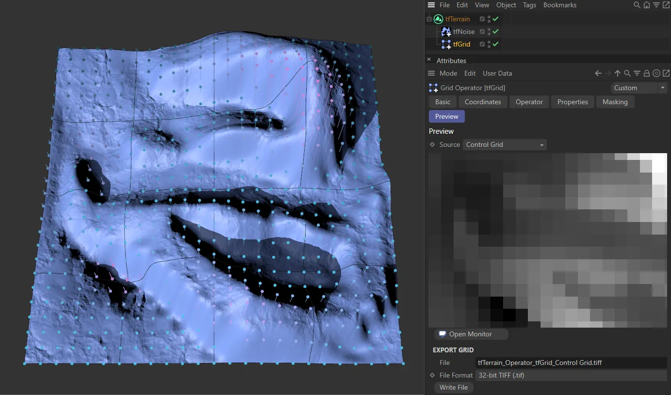
The Control Grid option in the Source parameter.
Export Grid
Section titled “Export Grid”This link field will give the address where the file will be saved to.
Clicking on the file icon to the right of the link field will open up the home computer file system.
File Format
Section titled “File Format”Select the format you wish to save as.
Write File
Section titled “Write File”Click this button to save the file.
Copyright © 2026 INSYDIUM LTD. All rights reserved.