mtEdgeSpline
Overview Video
Section titled “Overview Video”Introduced in Build 1480
mtEdgeSpline generates custom splines from the base geometry.
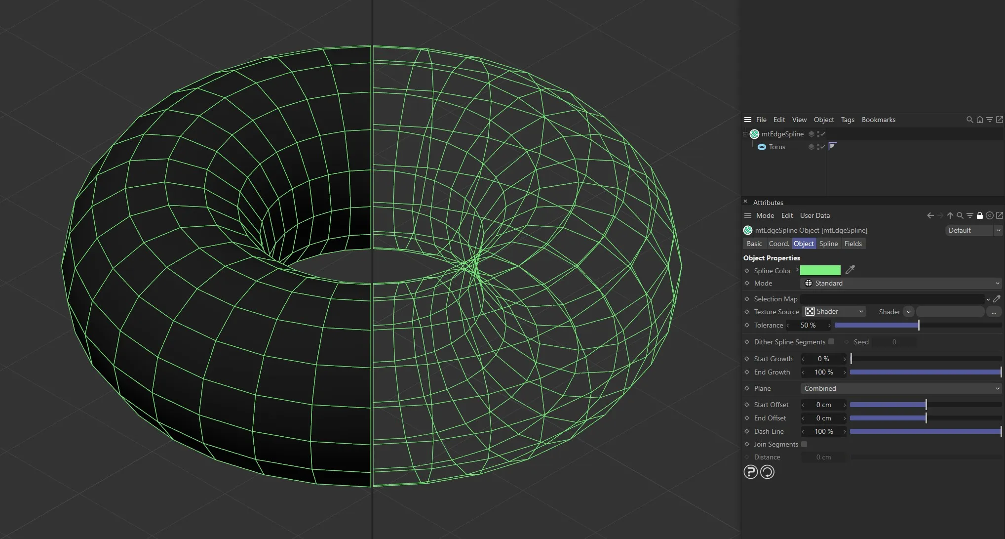
Torus as a child of mtEdgeSpline, with Mode set as Standard.
Object tab
Section titled “Object tab”Spline Color
Section titled “Spline Color”You can choose the generated spline color using the color picker.
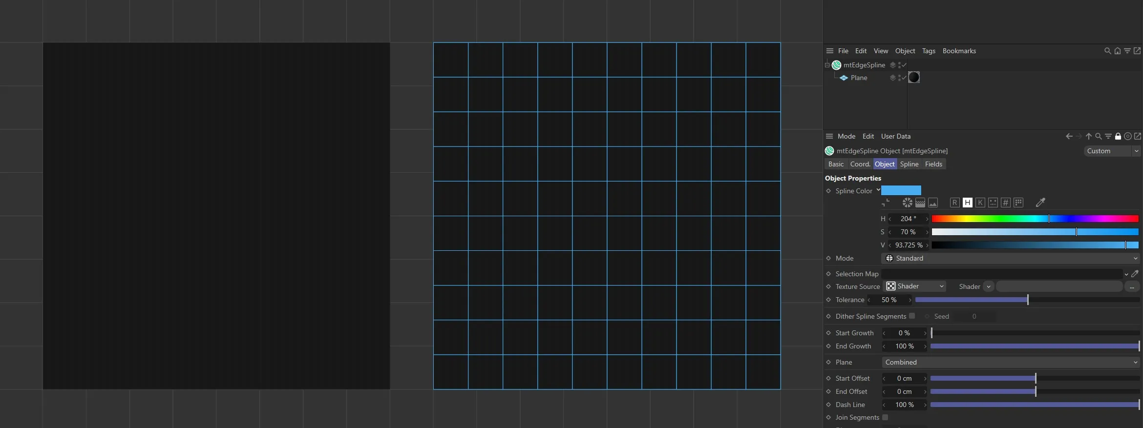
Spline Color has been set to blue for the Plane on the right.
There are five different spline types to choose from: Standard, Curvature, Contour, Outline and Intersection.
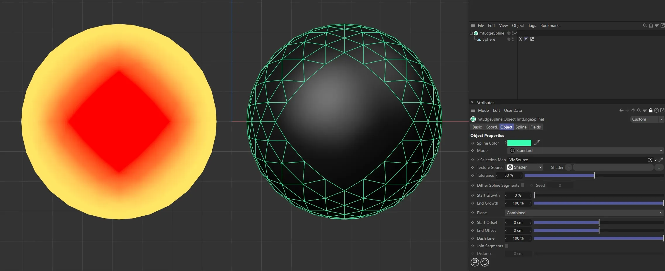
Standard
Section titled “Standard”Edges are generated based on the existing mesh geometry.
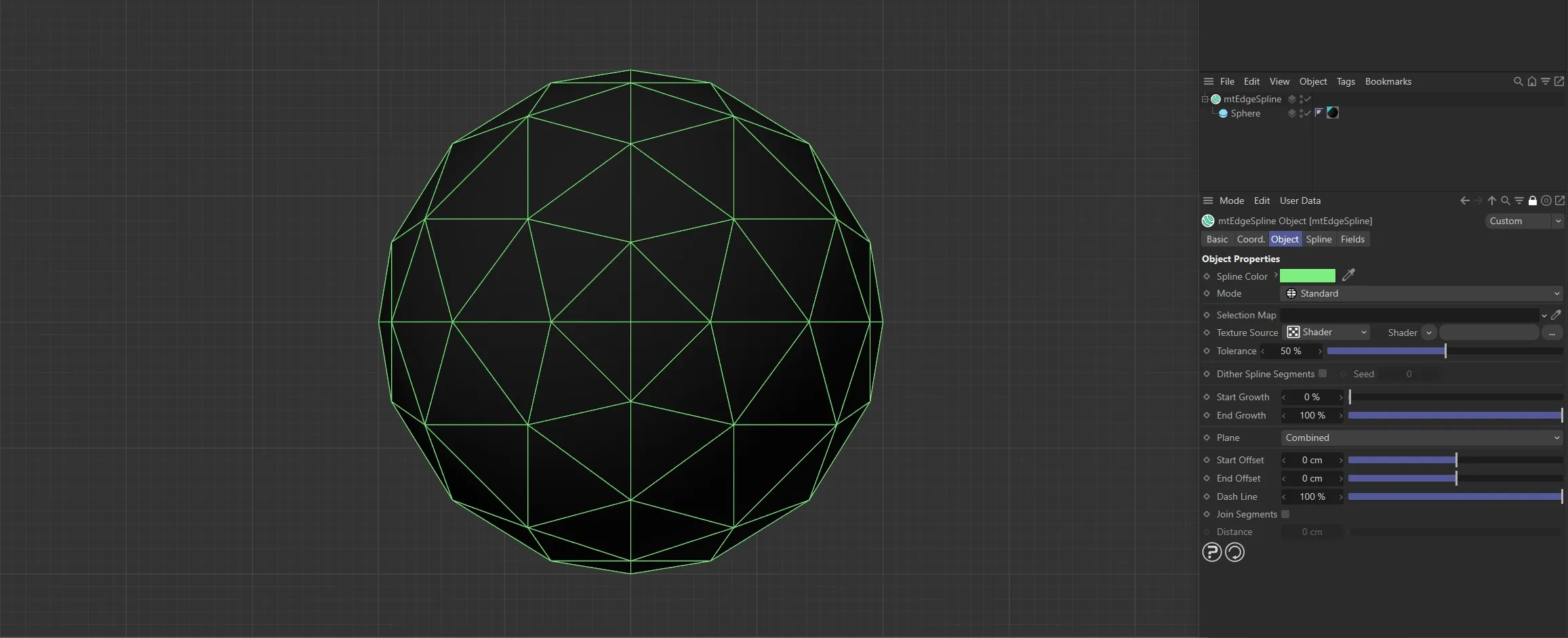
The mtEdgeSpline Mode is set to Standard for this Sphere. All of the original base mesh edges are being used to generate the spline.
Curvature
Section titled “Curvature”Splines are generated based on the curvature of the geometry.
Use the Curvature Angle slider to set the threshold.
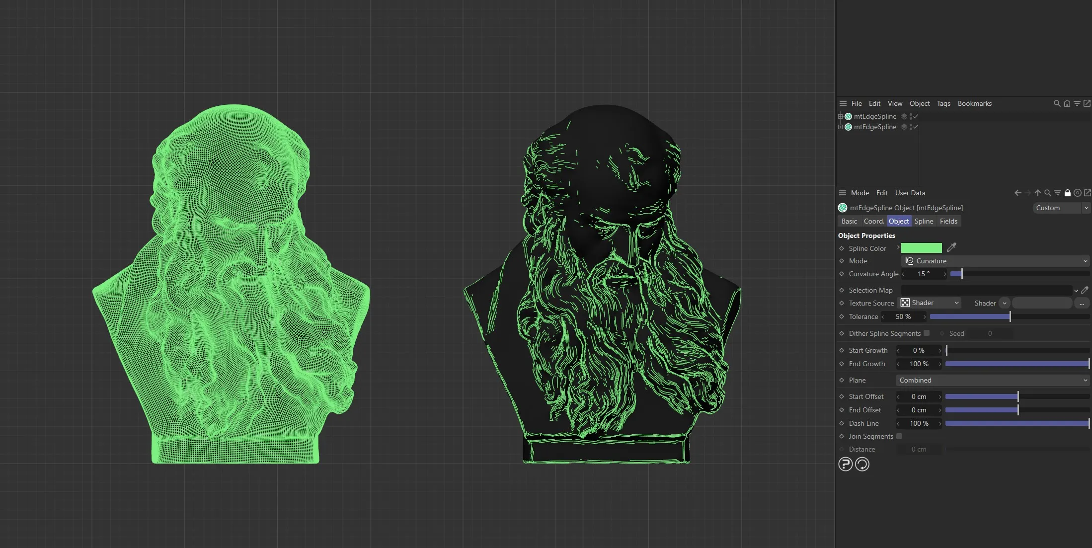
mtEdgeSpline generator Mode for both set to Curvature. The left generator has a Curvature Angle of 0 (zero) degrees. The right generator has a Curvature Angle of 16 degrees.
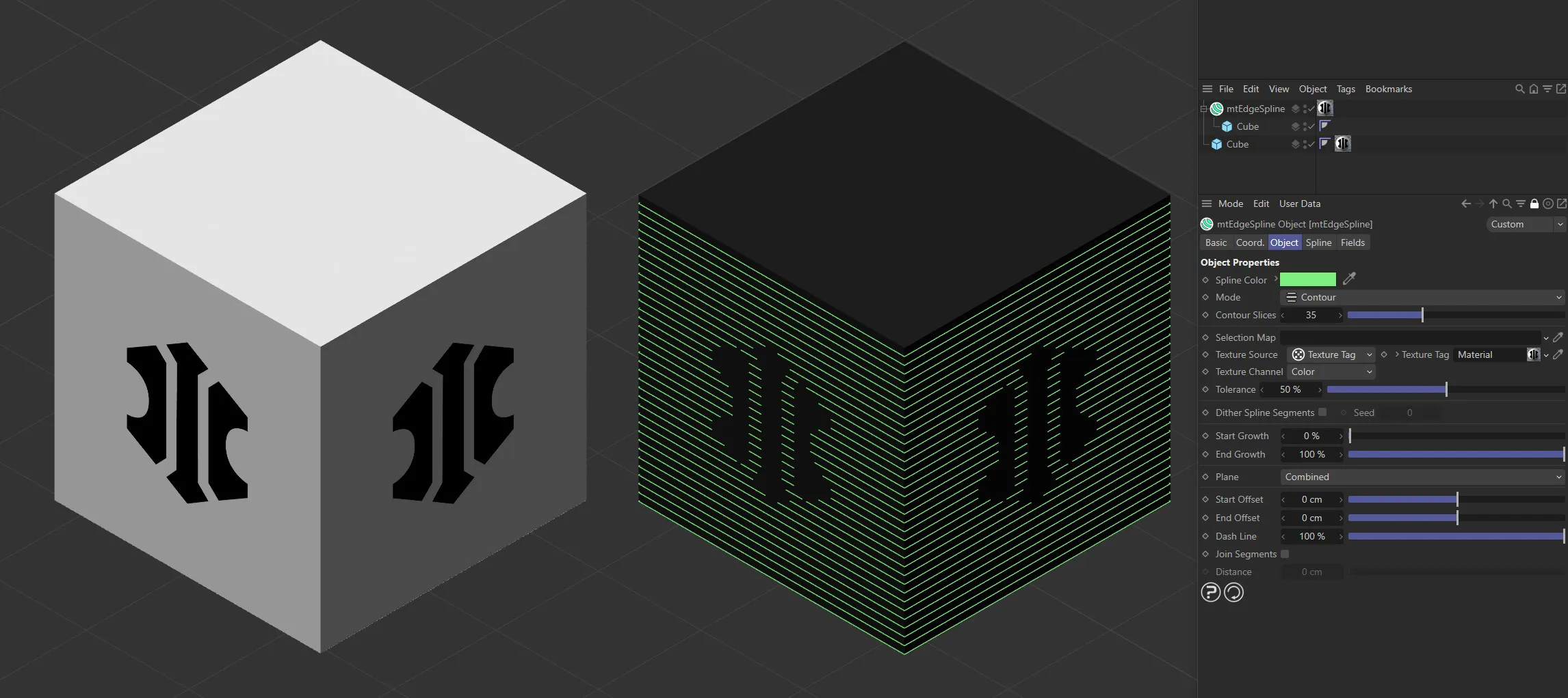
Contour
Section titled “Contour”Evenly-spaced contour splines are generated.
Use the Contour Slices setting to adjust the amount.
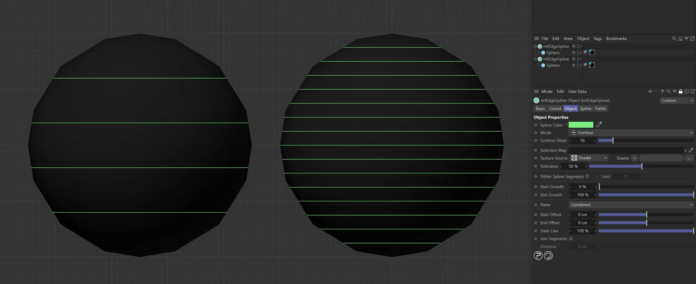
mtEdgeSpline Mode is set to Contour. The left generator has Contour Slices set to 5 and the right generator has Contour Slices set to 16.
Outline
Section titled “Outline”Splines are generated based on the object silhouette.
This is dependent on the viewing angle, so splines will behave dynamically with moving cameras.
With an Outline Angle of 0 (zero) degrees, splines are restricted to the silhouette.
You can create thicker outlines and shading effects by increasing the Outline Angle value.
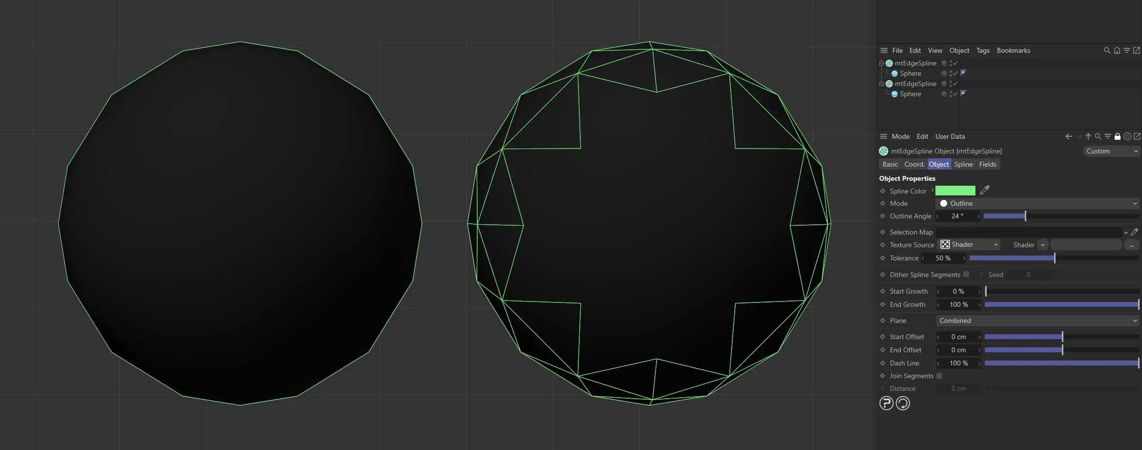
Both mtEdgeSpline generators Mode setting is Outline. The left generator has an Outline Angle of 0 (zero) degrees. The right generator has an Outline Angle of 24 degrees.
Intersection
Section titled “Intersection”Splines are generated where the surfaces of objects intersect.
Drag objects, which you want the base geometry to intersect, into the Objects link field.
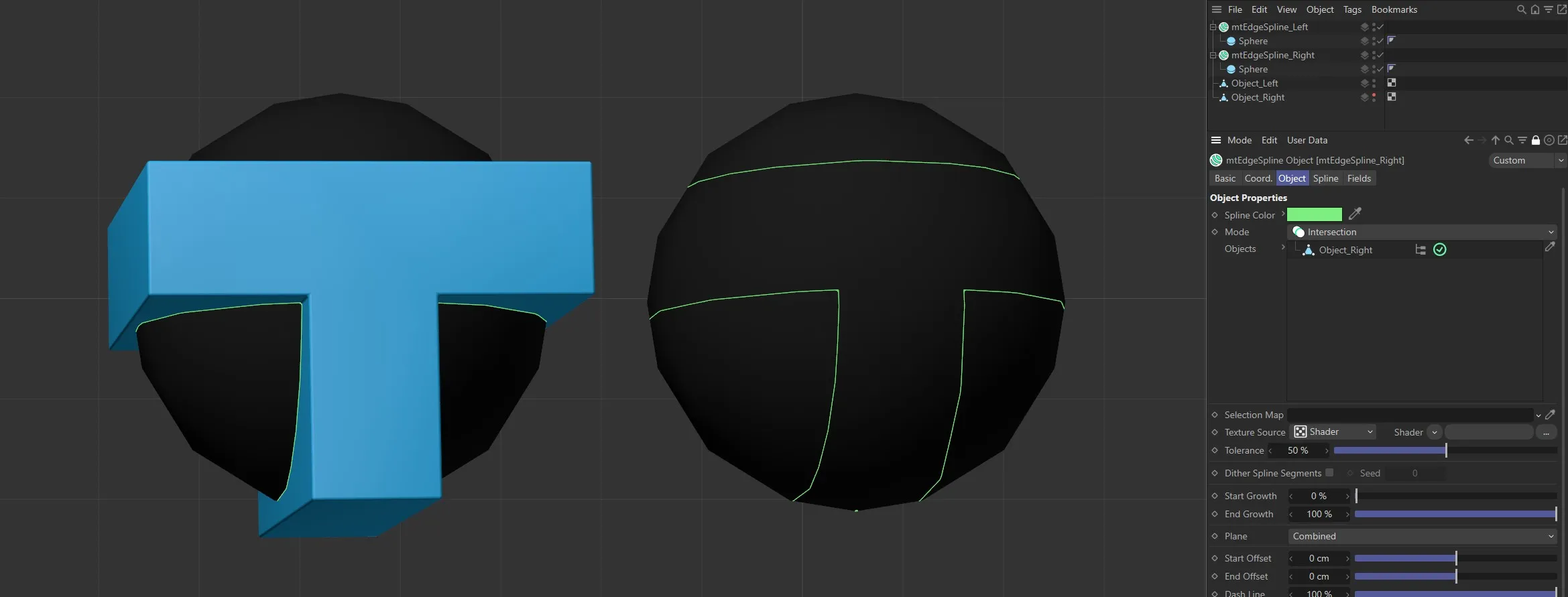
Both Spheres have mtEdgeSpline generator object Mode set to Intersection, both with identical intersecting objects. The intersecting object on the left is visible and the resulting generated spline is visible on the right.
Selection Map
Section titled “Selection Map”You can use a vertex map or selection tags to define where splines are generated.
Drag the tag from the Object Manager into the Selection Map link field.
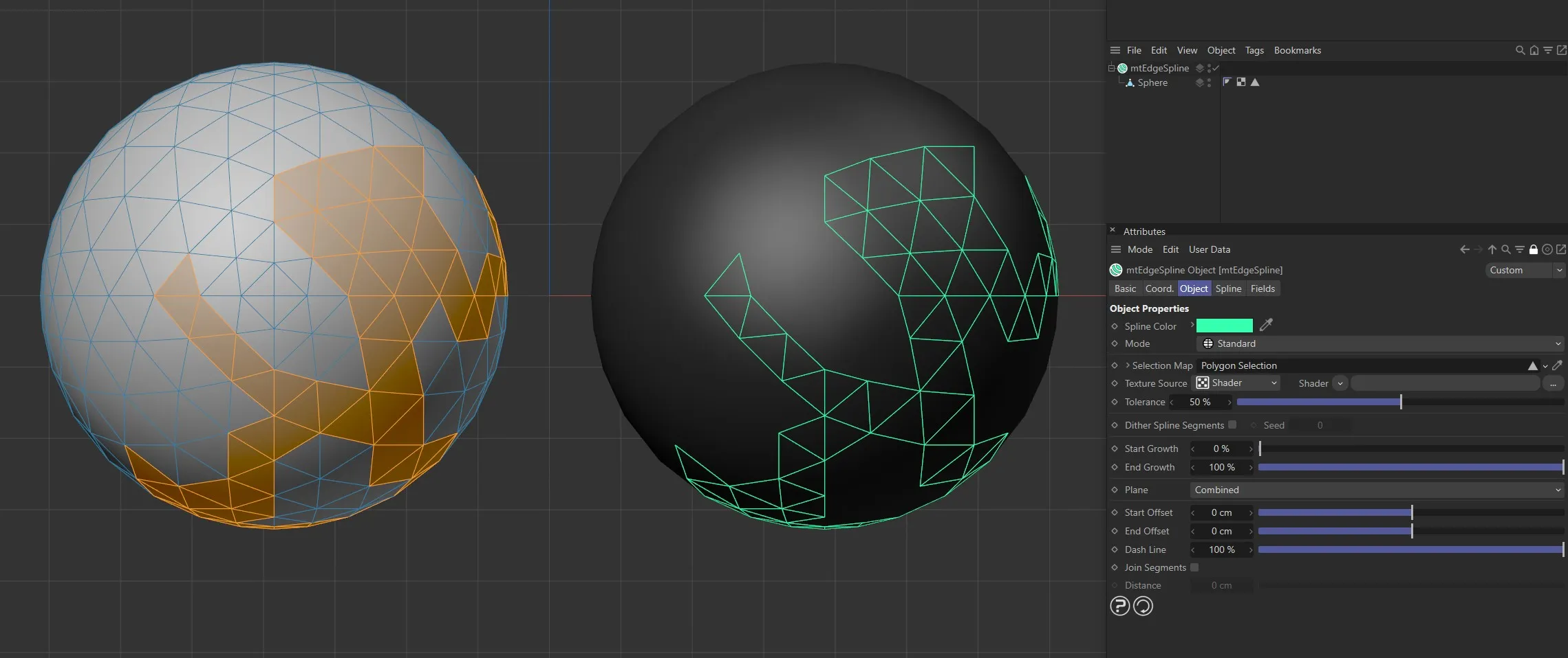
The Sphere on the left has a polygon selection tag, which is displayed in the viewport. An identical Sphere is on the right, as a child of a mtEdgeSpline, driving the generated edge spline.
The Sphere on the left has a vertex map, which is displayed in the viewport. An identical Sphere is on the right, as a child of a mtEdgeSpline. The vertex weights are driving the generated spline setting.
Texture Source
Section titled “Texture Source”You can use shaders, images and even animated video sequences to control where splines are generated.
There are two options: Shader and Texture Tag.
Both use color value to define which areas are selected.
Shader mode
Section titled “Shader mode”Shader
Section titled “Shader”Use the Shader drop-down arrow to select an image, sequence or shader.
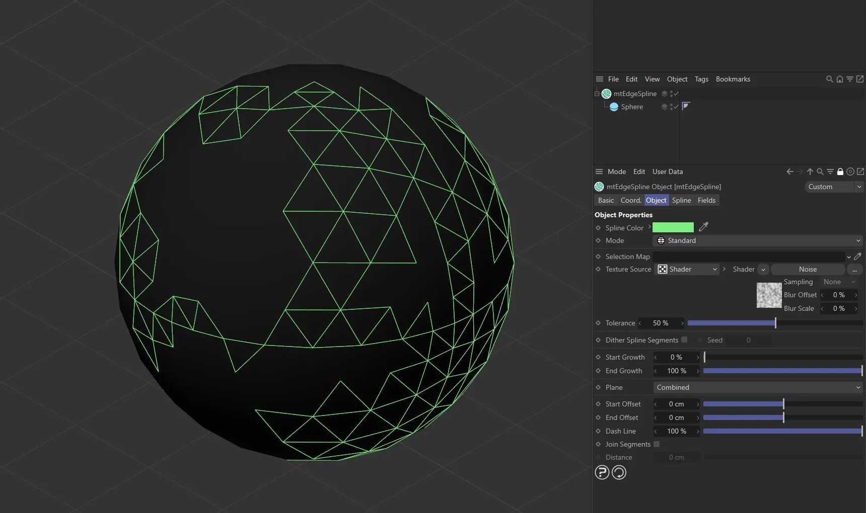
The Noise shader with mtEdgeSpline is driving the generated spline setting on this Sphere.
Texture Tag mode
Section titled “Texture Tag mode”This mode requires a Cinema 4D material.
Place the material on the mtEdgeSpline and you will see a texture tag appear alongside it in the Object Manager.
Drag this texture tag into the link field.
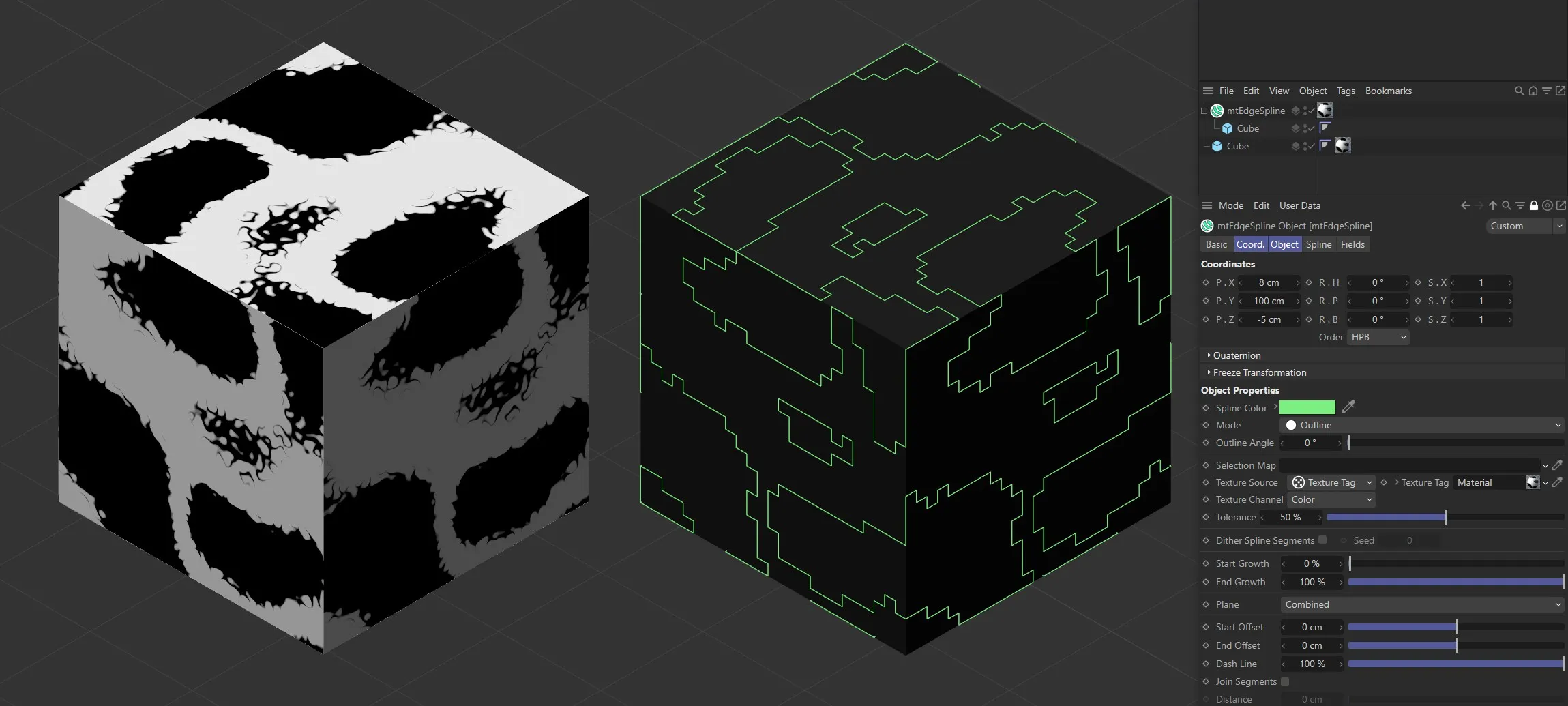
Noise shader with mtEdgeSpline Mode set to Outline, with Outline Angle at 0 (zero) degrees.
Bitmap with mtEdgeSpline Mode set to Contour.
Animated video sequence driving the generation of splines with Mode set to Intersection.
Texture Channel
Section titled “Texture Channel”Use the Texture Channel pull-down to select which material channel you wish to reference.
This is set to Color by default.
Tolerance
Section titled “Tolerance”Use the Tolerance slider to adjust the point at which splines are generated.
Lower tolerance values will allow darker areas to be included.
Higher tolerance values will allow only lighter areas to be included.
Illustrating the Tolerance slider, which is driven by the Noise shader.
Dither Spline Segments
Section titled “Dither Spline Segments”When using a Texture Source you are able to create a feathered edge effect by dithering the spline segments.
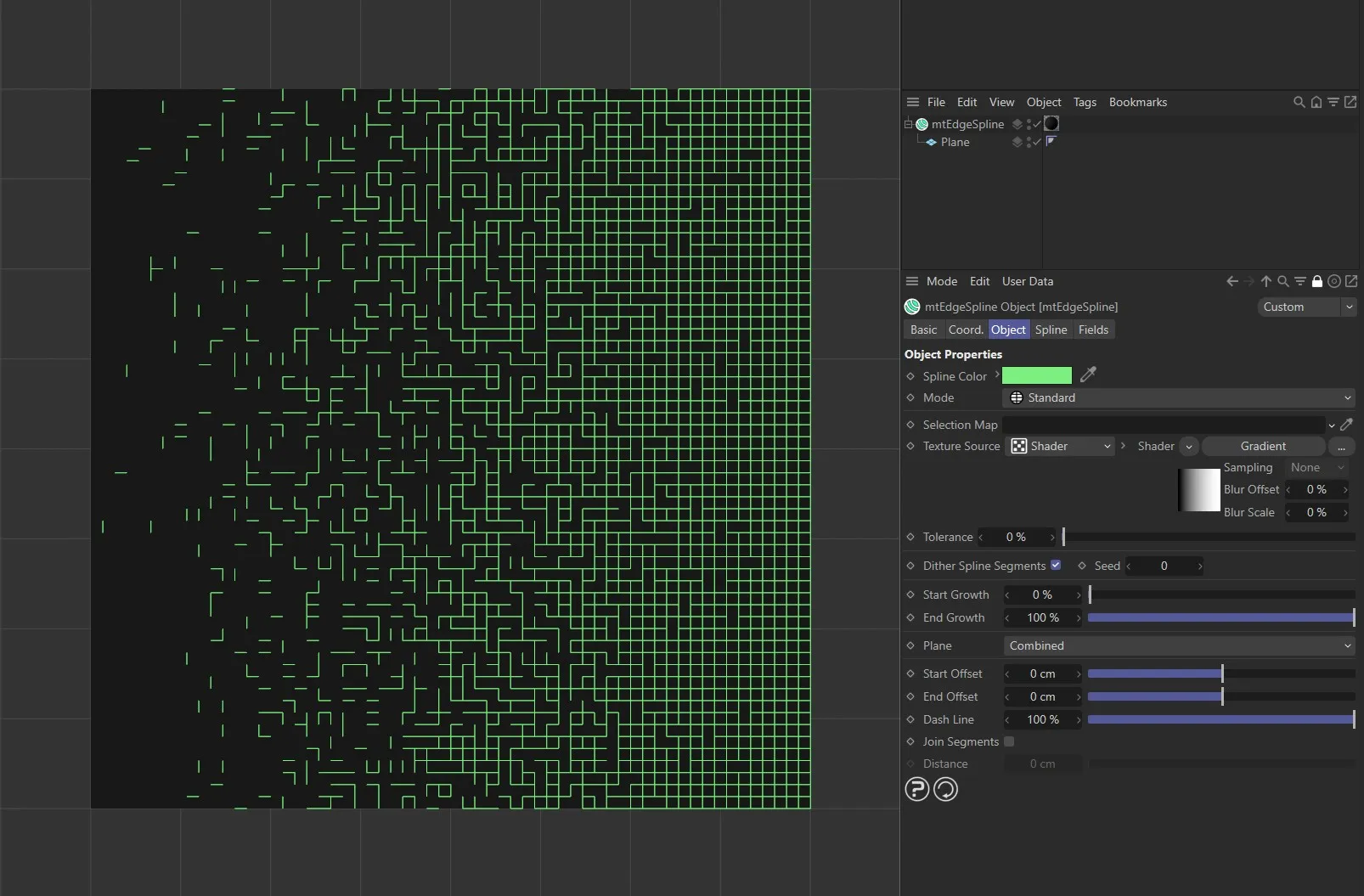
Dither Spline Segments enabled with mtEdgeSpline, driven by a Gradient shader.
Change the Seed value to generate a new random dither.
Scale Offsets
Section titled “Scale Offsets”Clones and offsets the edge spline in steps, determined by the Scale Offset Size value.
By default, the setting is 0 (zero).
Increasing this value, with the Scale Offset Mode set as Incremental will give you a clone for each step.
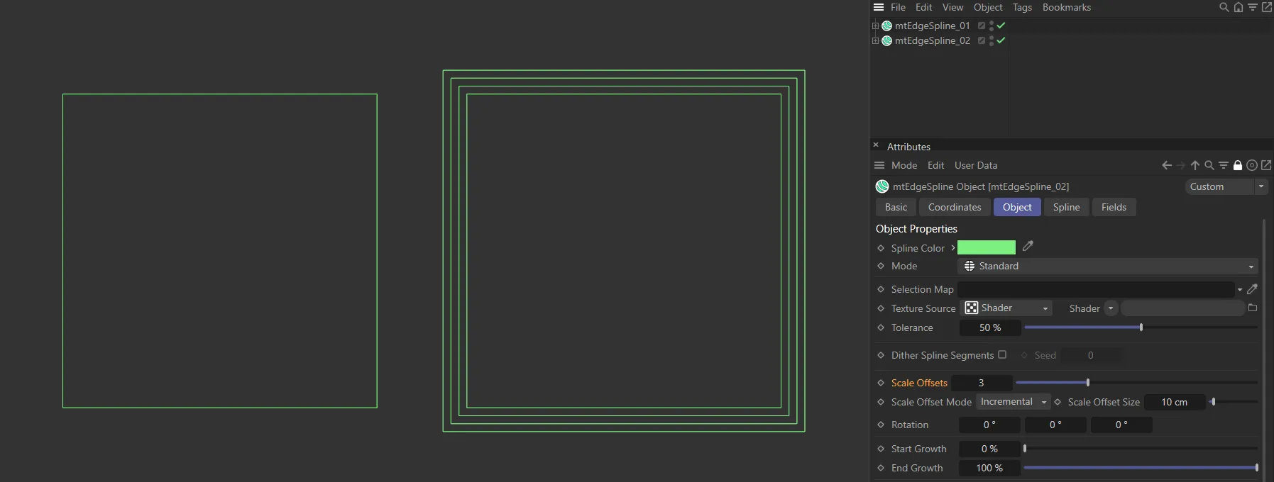
Scale Offsets value at 0 (zero) on the left and 3 on the right, in Incremental mode, expanding the size of the original geometry by two steps, each of 10cm, set in the Scale Offset Size parameter.
Scale Offset Mode
Section titled “Scale Offset Mode”Set at Incremental by default.
The alternative setting is Total.
Incremental mode
Section titled “Incremental mode”Each step is an increment of the previous, based on the Scale Offset Size setting making the object larger with each clone.
For example, a Scale Offsets value of 5, will result in the original object and 5 clones.
Each clone will be offset by the Scale Offset Size value.
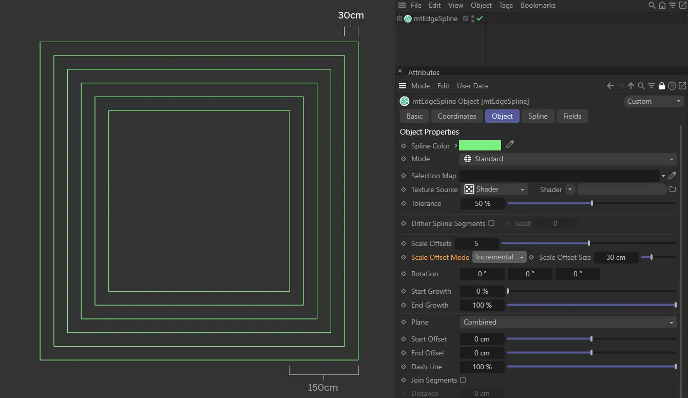
Scale Offset Mode set at Incremental with a Scale Offset value of 5, giving a total offset of (5 x 30cm) 150cm, away from the original spline.
Total mode
Section titled “Total mode”The Scale Offset Size setting is the total offset, with each step being a part of that.
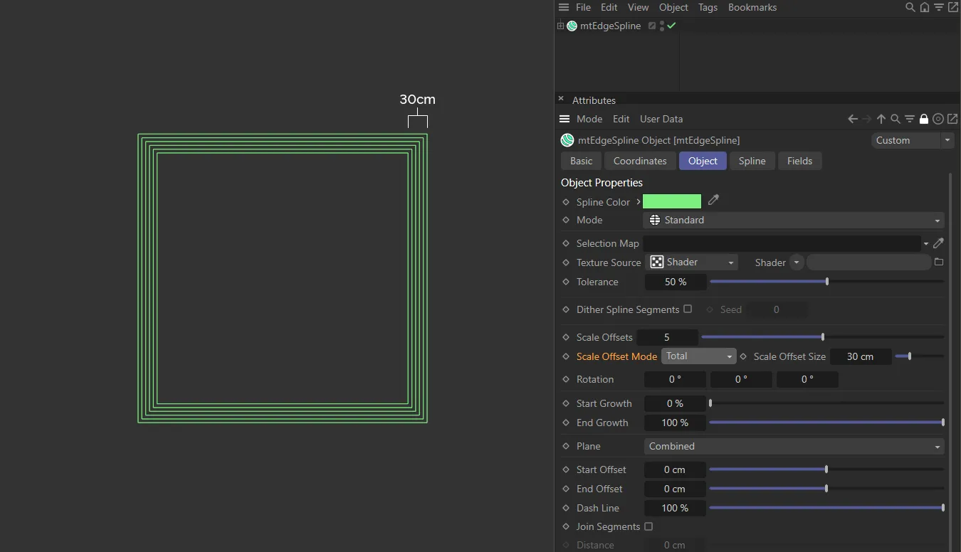
Scale Offset Mode set at Total, again with a Scale Offset value of 5. This time the total offset is 30cm, determined by the Scale Offset Size setting, with the new clones equally distanced in-between.
Scale Offset Size
Section titled “Scale Offset Size”The size of the offset, dependent on the Scale Offset Mode setting.
Rotation
Section titled “Rotation”Rotates the offset in the different axes.
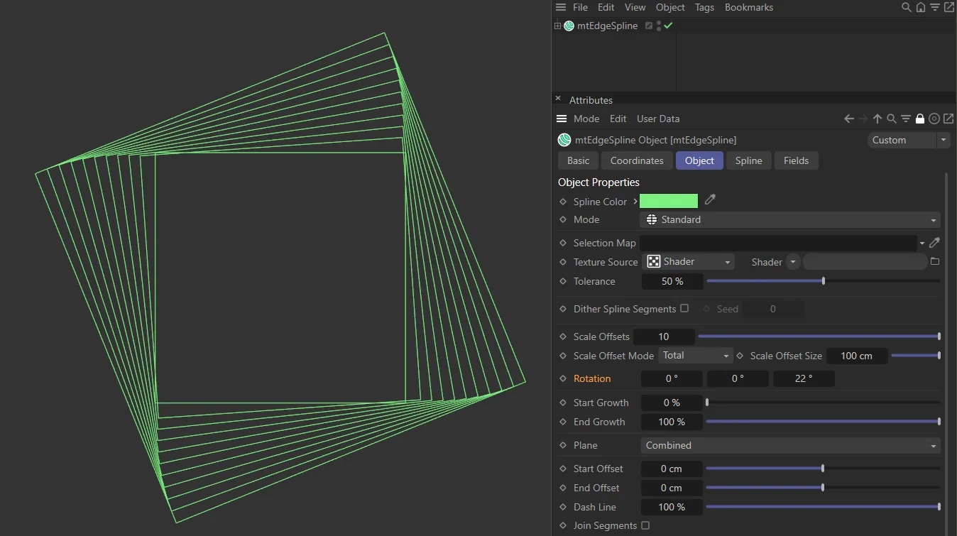
Here the Rotation is set at 22 degrees in the Z-axis, rotating the ten offsets to a total of 22 degrees.
Start Growth
Section titled “Start Growth”You can adjust the length of the spline by changing its start point.
End Growth
Section titled “End Growth”You can also adjust the length of the spline by changing its end point.
Animated sequence with mtEdgeSpline, demonstrating the Start Growth and End Growth sliders.
Combined
Section titled “Combined”Horizontal (U) and vertical (V) splines are both generated.
Only horizontal splines are generated.
Only vertical splines are generated.
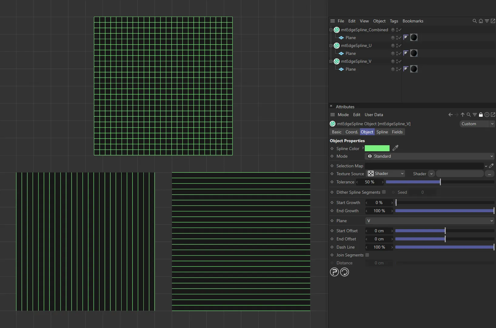
In this image, the first plane, at the top, has Plane set to Combined. As a result, both horizontal and vertical lines are generated. On the lower left, the Plane setting is V. Here, only vertical lines are being generated. On the lower right, the Plane setting is U and only horizontal lines are being generated.
Start Offset
Section titled “Start Offset”Offset the start point of each spline segment.
End Offset
Section titled “End Offset”Offset the end point of each spline segment.
Video sequence, with mtEdgeSpline, demonstrating the Start Offset and End Offset sliders.
Dash Line
Section titled “Dash Line”Lower this slider, from its default value of 100%, to create a dash line effect.
Video sequence with mtEdgeSpline demonstrating the Dash Line slider.
Join Segments
Section titled “Join Segments”mtEdgeSpline creates multiple segment splines.
You can join these segments by activating this setting.
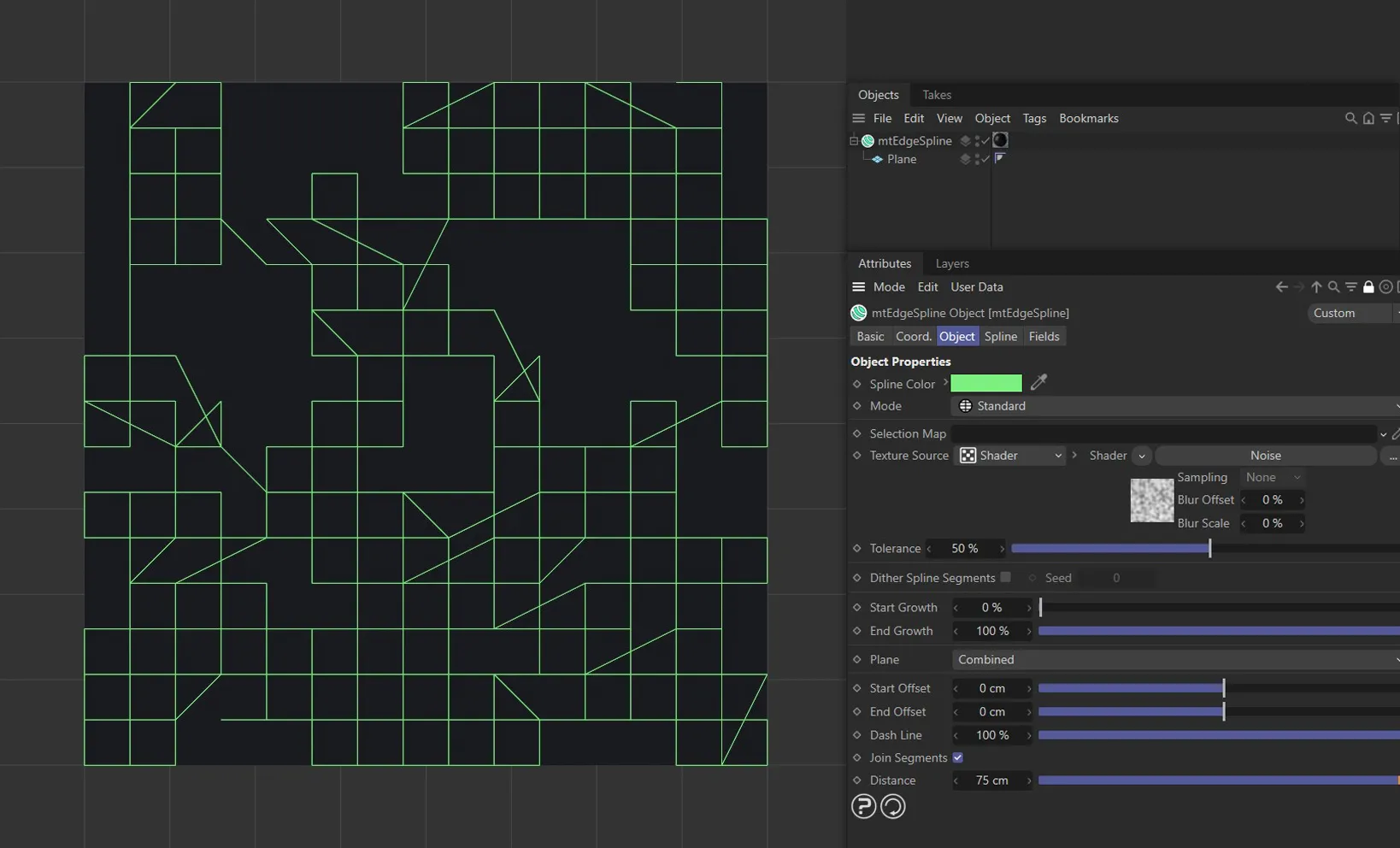
Join Segments, enabled in mtEdgeSpline, joining up segment splines.
Distance
Section titled “Distance”Segments will only be joined if they are within this Distance setting.
Spline tab
Section titled “Spline tab”Choose from Linear, Cubic, Akima, B-Spline or Bezier spline types.
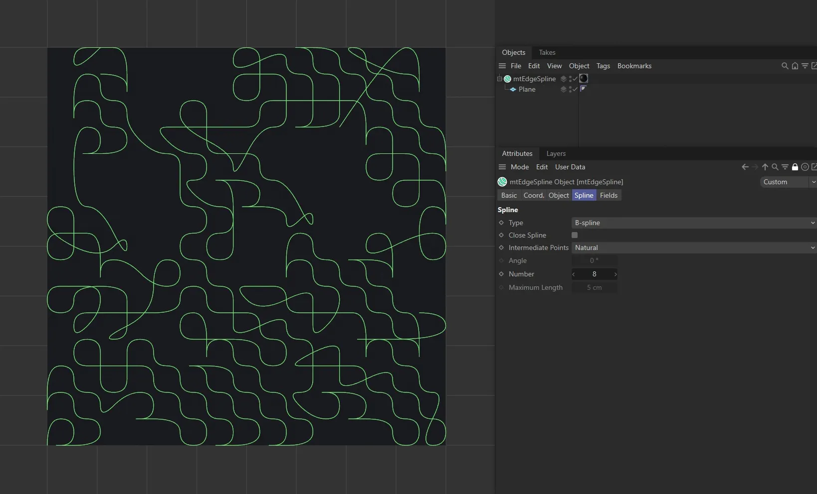
mtEdgeSpline set to B-spline Type.
Close Spline
Section titled “Close Spline”This will create a closed spline by connecting the start and end points.
Intermediate Points
Section titled “Intermediate Points”You can choose how intermediate points are generated from the usual options.
Number
Section titled “Number”In Natural and Uniform modes, use this field to set the number of intermediate points.
In Adaptive and Subdivide modes, use this Angle threshold setting to control the generation of intermediate points on curved edges.
Maximum Length
Section titled “Maximum Length”In Subdivide mode, use this length threshold to limit the generation of intermediate points on straight edges.
Display tab
Section titled “Display tab”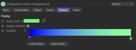
Display tab settings.
Spline Color
Section titled “Spline Color”Set as green, by default, you can change the color of the splines.
Display Gradient
Section titled “Display Gradient”This parameter enables the gradient coloring on the splines in the scene.
Fields tab
Section titled “Fields tab”You can use the Fields options to control where mtEdgeSpline operates.
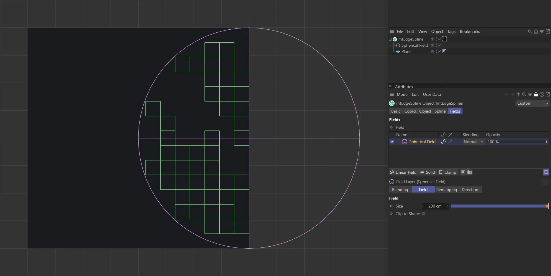
mtEdgeSpline with a Spherical Field driving the spline generation.
Copyright © 2026 INSYDIUM LTD. All rights reserved.