xpColor
xpColor is used to control and animate particle color.
Object properties
Section titled “Object properties”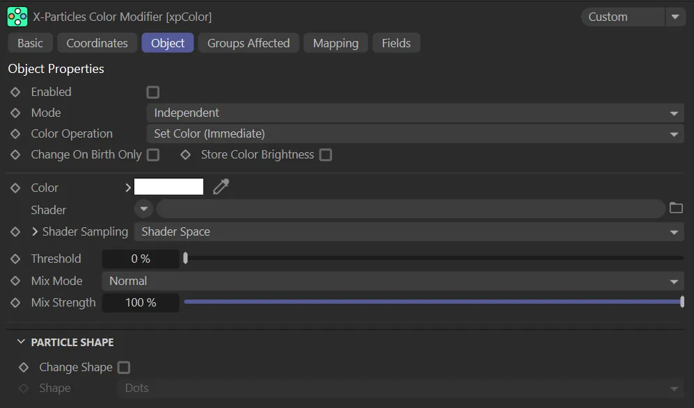
xpColor Object tab menu.
Enabled
Section titled “Enabled”Check this box to enable the xpColor modifier.
Animation to demonstrate xpColor being enabled and the resulting particle change to the Color setting of red.
Set at Independent, by default.
You can change this to Action-Controlled.
Independent Mode
Section titled “Independent Mode”In this mode, particles will be affected if they come into the field of effect of the modifier.
Action-Controlled Mode
Section titled “Action-Controlled Mode”When in the Action-Controlled setting, the modifier will only act on a particle when told to do so by an action.
Color Operation
Section titled “Color Operation”The default mode is Set Color (Immediate) but there are a lot of other options, as shown in the image below.
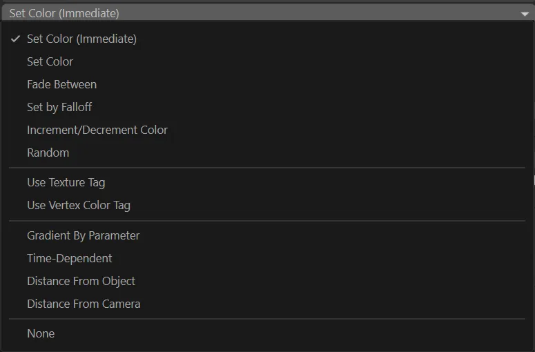
Color Operation menu.
Set Color (Immediate)
Section titled “Set Color (Immediate)”In this mode, the modifier will change the color as soon as the particle is in the modifier’s field of effect.
It is not an incremental change, as with Set Color, but it does require the particle to be within the modifier’s falloff field and will still be affected by the Threshold setting, if that is greater than zero.
This animation demonstrates the change of color within the modifier’s field; specifically the effect. Raising the Threshold setting adds a random variation to the point at which particles are affected.
Set Color
Section titled “Set Color”This option sets the color incrementally.
It only works if the modifier is using a field.
The rate of color change is driven by the field’s falloff.
If no field is active, this option will be no different from Set Color (Immediate).
A less uniform color change can be achieved by using the Threshold setting, explained further down this page.
In this animation, the same increase of the Threshold value is occuring, except the Color Operation mode is now Set Color; the immediate change, seen above, is not taking place.
Fade Between
Section titled “Fade Between”Similar to Set Color, but is simpler to use to get a smooth change in color.
With Fade Between, you simply set the color to change to and adjust the Fade Value to control the rate of change.
Choosing this option will reveal these additional two parameters.
Change Every
Section titled “Change Every”Sets how often the color is changed if Color Operation is set to Fade Between.
The default is one frame, so the particle color may change every frame.
Animation to show the effect of the Color Operation when set to Fade Between.
Fade Value
Section titled “Fade Value”Controls the rate at which the color changes if Color Operation is set to Fade Between.
The higher the value, the faster the change.
A value of 100% will cause an immediate change (assuming there is no falloff) while a value of 0 (zero) % will result in no color change at all.
This value can be mapped, if desired, to give even closer control.
Increasing the Fade Value percentage changes the color much faster, in this animation.
Set by Falloff
Section titled “Set by Falloff”In this mode, the color changes while the particle is in the modifier’s falloff, but reverts to the original color as it passes out of the falloff zone.
In this animation, with Color Operation set to Set by Falloff, the field is driving the color change.
Increment/Decrement Color
Section titled “Increment/Decrement Color”In this mode, the modifier will change the color by a set amount, as long as the particle remains within the modifier’s falloff.
The rate of change is governed by the three rate of change parameters.
You can change the red, green and blue components at different rates, if desired.
Selecting this option reveals additional parameters.
With Color Operation set to Increment/Decrement Color, the effect of the Red, Green and Blue Rate of Change sliders is demonstrated here.
Red/Green/Blue Rate of Change
Section titled “Red/Green/Blue Rate of Change”These parameters are used in conjunction with the Increment/Decrement Color mode.
The maximum value is 255, which will cause an instant color change.
A value of zero will result in no change.
Values less than zero will reduce the color values for each component.
Random
Section titled “Random”The modifier assigns a random color to each particle.
This animation shows the effect of the Color Operation setting of Random, with a random color being assigned to each particle.
Use Texture Tag
Section titled “Use Texture Tag”With this mode, you can drag a texture tag into the Texture Tag link field and the particle color will be sampled from the shader in that tag.
The sampled color will be blended with the color from the Color setting, depending on the Mix Mode and Mix Strength settings.
The following two parameters will be available.
In this animation, the Color Operation is set to Use Texture Tag. The Material in the Texture Tag field is animated, driving the color change on the Torus primitive over time. This then drives the particle color change.
Texture Tag
Section titled “Texture Tag”Only available in Use Texture Tag mode.
Drag the tag to be sampled into this field.
Channel
Section titled “Channel”Only available in Use Texture Tag mode; this is the channel to sample from (Color, Luminance, etc.).
The channel does not have to be used in the material.
You can set up an unused channel and sample from that if desired.
Use Vertex Color Tag
Section titled “Use Vertex Color Tag”If you select this option you can drag a vertex color tag into the link field which appears and the modifier will take the particle color from the tag.
Gradient by Parameter
Section titled “Gradient by Parameter”In this mode, the xpColor modifier functions in a similar way to if you had selected Gradient Parameter from the Color Mode menu in the emitter’s Display tab.
Using this method can offer more control, as you can use fields to determine where, in 3D space, the color changes are occurring, while still using parameters, such as age.
In this animation, with Color Operation set to Gradient By Parameter (and the Gradient setting driving the new colors), the field is determining where the color change is taking place.
Time-Dependent
Section titled “Time-Dependent”This mode displays a color gradient and, when the particle enters the modifier’s falloff, it will change the color to the color on the left of the gradient.
Then, over time, it will change the color to the color on the right of the gradient.
How long it takes to make the full change is governed by the Time to Completion parameter.
When the color change is complete, what the modifier does then is governed by the On Completion parameter.
The On Completion setting of Do Nothing is demonstrated here. After the Time to Completion value of 25 frames has been reached, each particle maintains its final color.
The On Completion setting of Wrap to Start is demonstrated here. Again, at the Time to Completion value of 25 frames, the color will be changed back to the color at the left of the gradient and the process repeated.
With Color Operation set to Time-Dependent and On Completion in the Reverse mode, every 25 frames the color gradient is reversed, as driven by the Time to Completion value set.
Distance from Object
Section titled “Distance from Object”This is the same as for the Time-Dependent mode but the rate of change is governed by the distance of the particle to an object in the scene.
With this mode, two additional settings are available: Nearest Distance and Furthest Distance.
All particles closer to the object than the nearest distance will have the color at the left of the gradient, while all particles farther away from the object than the furthest distance will have the right-hand gradient color.
Particles with a distance from the object in between the two distance values will have a color somewhere along the length of the gradient.
This animation demonstrates the Distance From Object setting. The Gradient setting again drives the color, with the yellow color on the left of the gradient being applied to particles closest to the Cube object and the pink, on the right, applied to those furthest away.
Distance from Camera
Section titled “Distance from Camera”Exactly the same as the Distance From Object mode, except that the current camera is used instead of a scene object.
In this animation, the Color Operation setting of Distance From Camera is shown. No matter where the camera moves to, the particles furthest away from it are changed to the pink color at the right of the Gradient setting and the closest take on the yellow, which is at the left.
Change on Birth Only
Section titled “Change on Birth Only”If enabled, the color is only changed for newly-created particles.
After that, the modifier will not affect the particle at all.
Store Color Brightness
Section titled “Store Color Brightness”If enabled, when the color is changed, the overall brightness will be stored as a particle data item.
This can then be used in data mapping.
Only available in Set Color, Set Color (Immediate), Fade Between and Set By Falloff modes.
This sets the particle color, in combination with color from a shader (if present).
Shader
Section titled “Shader”A link field for a channel shader.
If Color Operation is set to Set Color (Immediate), Set Color, Fade Between or Set By Falloff, there is the option to use a shader to generate the color.
In these modes, further parameters become available.
In this animation, a Noise shader, with the default Shader Sampling setting of Shader Space, is driving the color and the effect of increasing the Threshold parameter is being shown.
Shader Sampling
Section titled “Shader Sampling”This menu determines how the shader is sampled.
The default setting is Shader Space; this will sample the color at the particle position in the 3D world.
Random (Variable) will sample the shader at a different random point in each frame.
With the same set up, in this animation the Shader Sampling mode is Random (Variable), sampling the shader at a different random point in each frame.
Finally, in Random (Fixed) the shader will be sampled at a point which will always be the same point for each particle, but will be a different point for different particles.
This third animation shows the Shader Sampling mode of Random (Fixed), sampling the shader at the same point for each particle.
Scale U, Scale V, Scale W
Section titled “Scale U, Scale V, Scale W”These three parameters control the size of the shader across the sample space.
If the Tile parameter is enabled, a bitmap will be tiled across the sample space and the number of tiles is controlled by these parameters.
If Tile is unchecked, the bitmap is simply scaled.
Procedural shaders are scaled using these parameters but the Tile parameter has no effect.
Offset U, Offset V, Offset W
Section titled “Offset U, Offset V, Offset W”The shader will be offset by these amounts in the respective direction.
Mirror U, Mirror V, Mirror W
Section titled “Mirror U, Mirror V, Mirror W”Checking these boxes will mirror the shader across the respective axis.
If a bitmap is used, enabling this will cause it to be tiled across the sample space.
The number of tiles is controlled by the Scale U and Scale V settings.
The setting has no effect on procedural shaders.
Gradient
Section titled “Gradient”The color gradient used in the the gradient modes.
Only available if Color Operation is set to Gradient By Parameter, Time Dependent, Distance From Object or Distance From Camera.
In these modes, further parameters become available.
Gradient Parameter
Section titled “Gradient Parameter”Only used in the Gradient By Parameter mode.
The color change is dependent on one of several particle parameters.
The parameters available are: 3D Linear, Age, Direction, Distance Traveled, Fire, Fluid Density, Fuel, Mass, P-P Distance, Radius, Speed, Smoke and Temperature.
To determine the position along the gradient to sample the color, the Min. and Max. settings are used.
You should alter these values to fit the expected range of the parameter used.
Some of these modes have their own particular settings, detailed below.
3D Linear
Section titled “3D Linear”In this mode, the gradient is used to color the particles depending on their position along a specified axis.
There are additional parameters available for this mode.
Linear Mode
Section titled “Linear Mode”The axis to use - X, Y or Z.
Axis Min
Section titled “Axis Min”The lowest position along the axis.
Axis Max
Section titled “Axis Max”The highest position along the axis.
This menu has two options: World and Local.
The position along the axis is the actual position in the 3D world.
the position is relative to the position of the object given in the Object setting.
This can be the emitter itself or any scene object.
Object
Section titled “Object”The object used if Space is set to Local.
If it is left empty, the world position is used instead.
Direction
Section titled “Direction”This is an absolute value; there is no min/max setting possible with this.
You can select the Direction Axis to test; this can be either Heading, Pitch or Bank.
Particle direction is a vector, with three components to indicate the amount of movement along each axis.
Each component can be between 0 and 1 and this is used as an index into the gradient to choose the color.
Fluid Density
Section titled “Fluid Density”This will only work if the SPH Fluid object is active in the scene.
P-P Distance
Section titled “P-P Distance”The distance to the nearest particle from the one to be colored.
It will only work if the Nearest Particle Data box has been checked in the emitter’s Extended Data tab, so that the particle holds the distance to the nearest other particle.
Min, Max
Section titled “Min, Max”These are the values which set the range for the parameter chosen in the Gradient Parameter setting.
These are not available for the Age or Direction parameters.
Direction Axis
Section titled “Direction Axis”The axis to use when Gradient Parameter is set to Direction.
The three options are Heading, Pitch and Bank.
Time to Completion
Section titled “Time to Completion”Only available if Color Operation is set to Time-Dependent. It is the amount of time taken to change the color from the left of the gradient to the color at the right of the gradient.
On Completion
Section titled “On Completion”This parameter is only available if Color Operation is set to Time-Dependent.
It governs what happens when the color change is completed.
The default setting is Do Nothing.
Alternatives are: Wrap to Start and Reverse.
Do Nothing
Section titled “Do Nothing”No further change to the particle color will occur.
Wrap to Start
Section titled “Wrap to Start”The color will be changed back to the color at the left of the gradient and the process repeated.
Reverse
Section titled “Reverse”The color change will be reversed; it will begin to change back to the color at the left of the gradient, taking the time in Time to Completion to reverse the change.
Object
Section titled “Object”The object to measure particle distance from if Color Operation is set to Distance From Camera.
Nearest Distance, Furthest Distance
Section titled “Nearest Distance, Furthest Distance”These parameters are only available if Color Operation is set to Distance From Object or Distance From Camera.
All particles closer to the object or camera than the nearest distance will have the color at the left of the gradient, while all particles farther away from the object or camera than the furthest distance will have the right-hand gradient color.
Particles with a distance from the object or camera in between the two distance values will have a color somewhere along the length of the gradient.
Vertex Color Tag
Section titled “Vertex Color Tag”A link field for a vertex color tag if you set Color Operation to Use Vertex Color Tag.
Threshold
Section titled “Threshold”This is a setting designed to introduce some random chance into the color change.
Each time the color is due to change for a particle, a random number is generated; if that number exceeds the threshold, the change will take place, but if it does not there will be no change.
You can see that a value of 0 (zero) % will always result in a change occurring; a value of 100% will mean that a change never occurs.
Mix Mode, Mix Strength
Section titled “Mix Mode, Mix Strength”Determine how the color from the Color and Shader fields are blended.
The standard four blend options are available.
The Mix Strength parameter governs the relative contribution of each color to the final result.
A value of 100% means that only the shader color is used, while 0 (zero) % will only use the Color field color.
These parameters have no meaning if no shader is present in the Shader field.
Particle Shape
Section titled “Particle Shape”Change Shape
Section titled “Change Shape”The xpColor modifier can also change the particle shape without changing the particle’s group.
The shape change will occur as soon as the particle enters the modifier’s field of effect.
It is not affected by any other parameter and is independent of the choice in Color Operation.
If Change Shape is enabled, this drop-down menu enables you to choose the new shape.
In this animation, with Change Shape enabled, once the particles reach the field, they are changing to the Shape setting of Circle.
Groups Affected tab
Section titled “Groups Affected tab”Groups
Section titled “Groups”To specify the group, drag and drop the desired Group object into this field.
This setting is useful if you want to ensure that the spawned particles are, or are not, affected by xpColor.
Mapping tab
Section titled “Mapping tab”The modifier’s settings can be mapped to particle data.
Use the dedicated manual page, below, for instructions on how this works.
Fields tab
Section titled “Fields tab”You can use the Fields options to control where xpColor operates.
Copyright © 2026 INSYDIUM LTD. All rights reserved.