tfWarp
tfWarp distorts the input height field, giving additional sculpting control on the X and Z axes, using a low-res control grid of 2D displacement vectors.
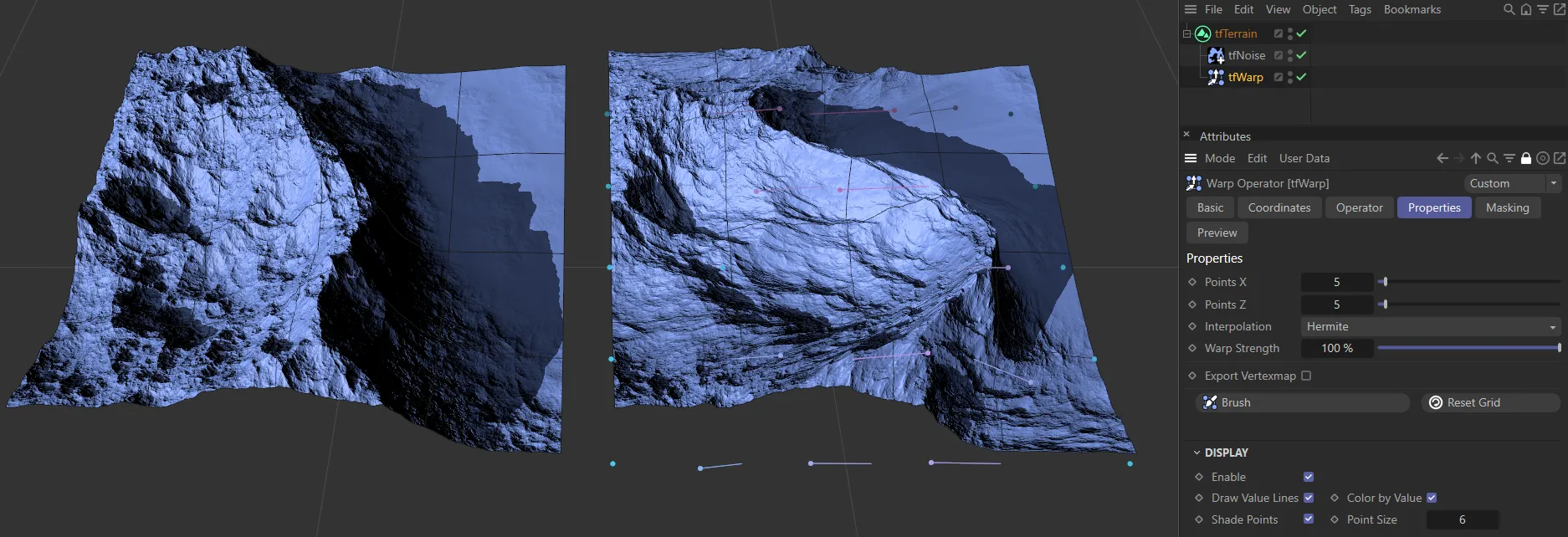
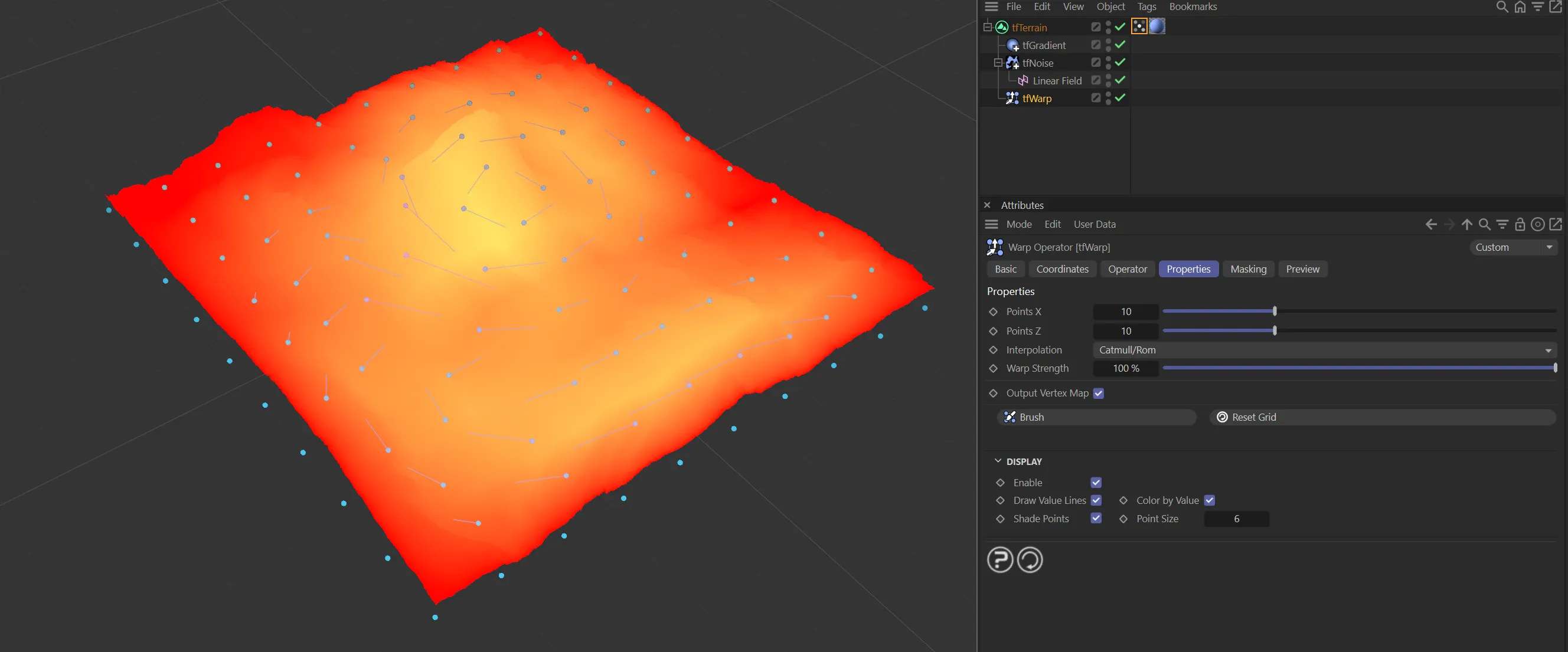
The tfWarp filter on the right-hand terrain is allowing sculpting through points on the X and Z-axes.
Properties
Section titled “Properties”The grid generates blue points (the default is 10 x 10) and each of the blue points can be clicked and dragged left and right inside the viewport to manually manipulate the terrain, creating deformation, or ‘warping’.
Once the points have been moved, they leave value lines, which indicate how far they have been deformed from their default state.
The deformed points also change color.
The most deformed points turn pink, with points in between being a lilac color.
Points X
Section titled “Points X”Controls the number of points in the X-axis.
Fewer points will create more deformation in the grid.
Conversely, more points will allow for more detailed distortion of the terrain.
Points Z
Section titled “Points Z”As above, this controls the number of points in the Z-axis.
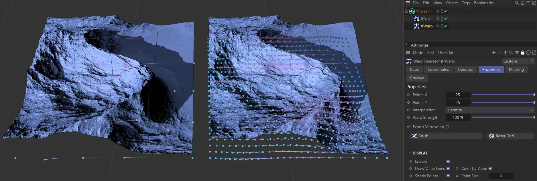
The terrain on the left has the default setting of 5 x 5 points. On the right, this has been increased to 25 x 25 points.
Interpolation
Section titled “Interpolation”Set as Catmull/Rom, by default.
The alternatives are: Nearest, Bilinear, Cosine, Bicubic and Hermite.
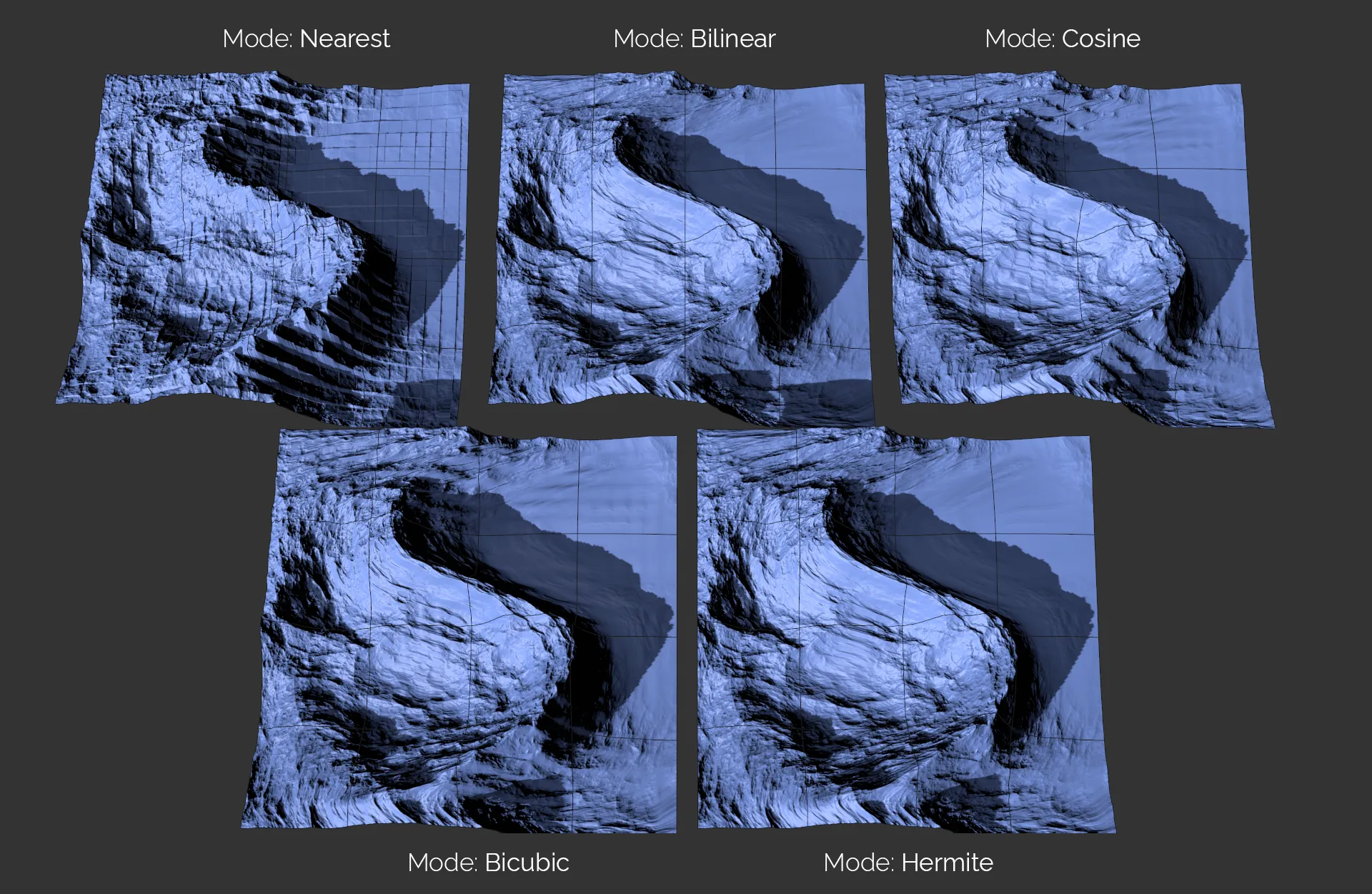
The original five Interpolation settings available (Catmull-Rom now added with 2024.2 update).
Nearest
Section titled “Nearest”Gives a ‘blocky’ look, with no interpolation at all, as shown above.
Bilinear
Section titled “Bilinear”The Bilinear setting is smooth between points, but gives hard edges.
Cosine
Section titled “Cosine”Cosine interpolation creates a smooth result, flattening the slope on grid points.
Bicubic
Section titled “Bicubic”This setting gives smooth deformation in the grid.
Hermite
Section titled “Hermite”This is very smooth, detailed and high quality, but rendering is slightly slower than the other modes.
Catmull/Rom
Section titled “Catmull/Rom”This option looks exactly like the Hermite interpolation but calculates almost twice as quickly.
Warp Strength
Section titled “Warp Strength”Sets the strength of the warping on the terrain.
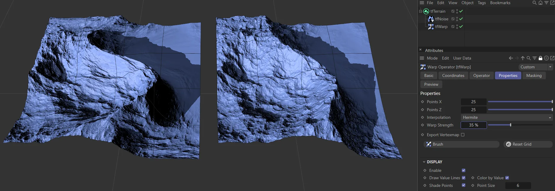
The terrain on the left has a Warp Strength of 100%, whilst it is lowered to 35% on the right-hand terrain.
Output Vertex Map
Section titled “Output Vertex Map”Checking this box will place a vertex map tag on tfTerrain in the Objects Manager.
Vertex map created on the terrain through enabling Output Vertex Map.
Clicking on this button takes you into the tfBrush tool, with its own settings (covered in depth in its own page).
Here you can ‘paint’ in the deformation intuitively, inside the viewport.
Clicking and dragging will create a deformation of points based on the Falloff curve.
Animation to demonstrate the effect of the tfBrush feature.
Radius
Section titled “Radius”This slider increases and decreases the radius of the brush.
The radius can also be adjusted by holding down the middle button on your mouse and dragging horizontally.
This animation shows the effect of the Radius slider with tfBrush.
Strength
Section titled “Strength”Set at 50%, by default, this can be reduced to give a lighter touch, or increase to give a heavier touch to the deformation.
The strength can also be adjusted by holding down the middle button on your mouse and dragging vertically.
In this animation, the Strength slider is being demonstrated, elevating the terrain.
Brush Mode
Section titled “Brush Mode”Depending on how you access tfBrush, the default setting is Brush in tfWarp.
The other settings available are: Pinch, Bulge and Relax.
Brush mode
Section titled “Brush mode”Lets you brush the warp grid points, similar to combing hair.
The Brush Mode in this animation is Brush.
Pinch mode
Section titled “Pinch mode”Pulls warp grid points towards the brush.
This animation shows the effect of Pinch in the Brush Mode.
Bulge mode
Section titled “Bulge mode”Pushes warp grid points away from the brush.
Animation to demonstrate the Brush Mode setting of Bulge.
Relax mode
Section titled “Relax mode”Softly blends the warp grid back to its initial state.
The Brush Mode is Relax in this animation.
Use Falloff
Section titled “Use Falloff”This is on, as the default setting.
Falloff
Section titled “Falloff”The Falloff curve determines the effect on the elevation patterns.
This will be further amplified by the deformation settings you have chosen.
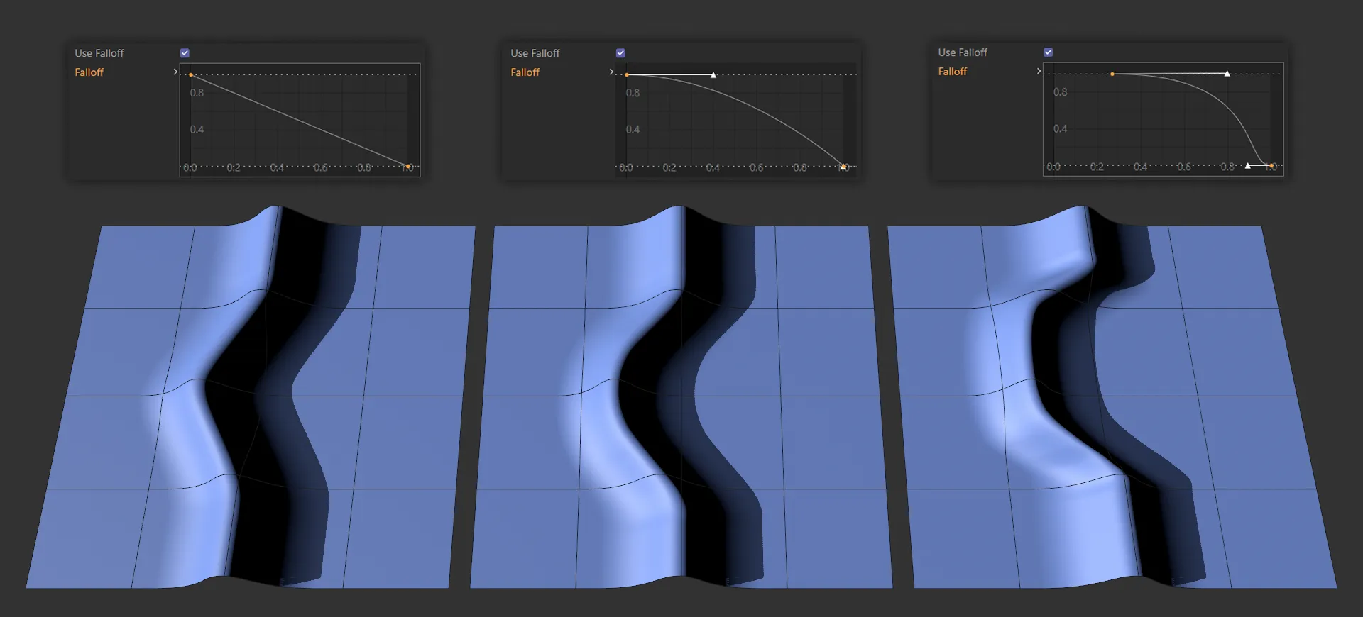
Here, there are three terrains being driven by the Falloff curve settings, above. The first, a linear curve; in the center, the default curve and, finally, an exaggerated bell curve.
Load Preset
Section titled “Load Preset”There are various preset falloff shapes available to load in from here.
Save Preset
Section titled “Save Preset”It is possible to save your custom falloff shapes for future use.
Auto-skip slow Operators
Section titled “Auto-skip slow Operators”The Auto-skip slow Operators option will temporarily deactivate successive operator objects that calculate too slowly.
This results in a (temporarily) less truthful viewport display, but it tremendously increases performance while making a brushstroke.
Reset Grid
Section titled “Reset Grid”Resets the grid to the default setting, so that all the points are at 0 (zero) cm.
Display
Section titled “Display”Enable
Section titled “Enable”Enabled, by default, displays the visual indicators in the grid, but they can be switched off.
Draw Value Lines
Section titled “Draw Value Lines”The value lines are on by default, but can be switched off.
Color by Value
Section titled “Color by Value”The color settings for the points (blue, lilac and pink) are on by default.
Switching this off will turn all the points yellow and the value lines will become green.
Shade Points
Section titled “Shade Points”Points are shaded by distance to the camera, making it easier to understand the control grid topology at a glance.
The nearest points are light blue, getting darker as they are further away.
Point Size
Section titled “Point Size”You can increase or decrease the point sizes.