mtSubDivider
mtSubDivider generates subdivisions on base geometry.
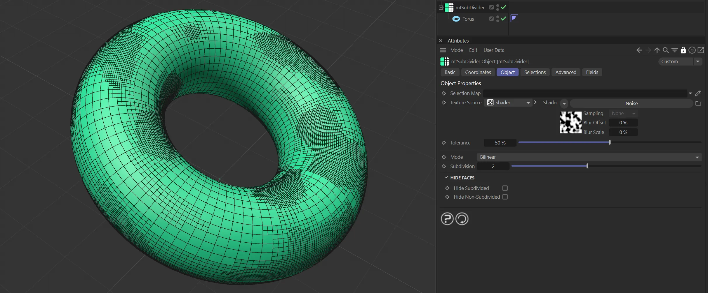
Torus as a child of mtSubDivider, using a Noise shader with Subdivision layers set to 2.
Object tab
Section titled “Object tab”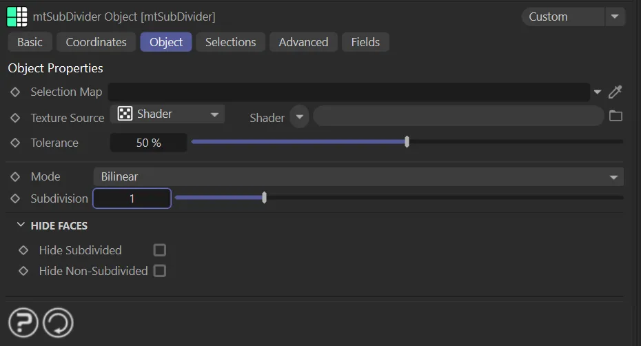
mtSubdivider, Object tab menu settings.
Selection Map
Section titled “Selection Map”You can use vertex map or selection tags to define where subdivisions are generated.
Drag the tag from the Object Manager into the Selection Map link field.
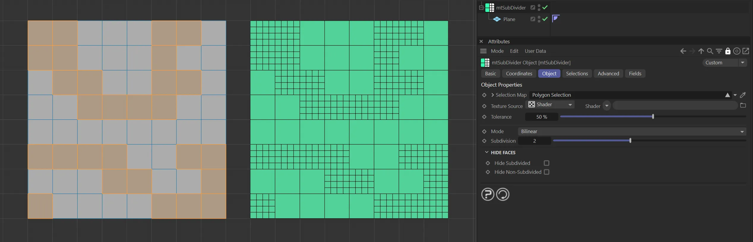
The Plane on the left has a polygon selection tag, which is displayed in the viewport. An identical Plane is on the right, as a child of a mtSubdivider, driving the subdivisions.
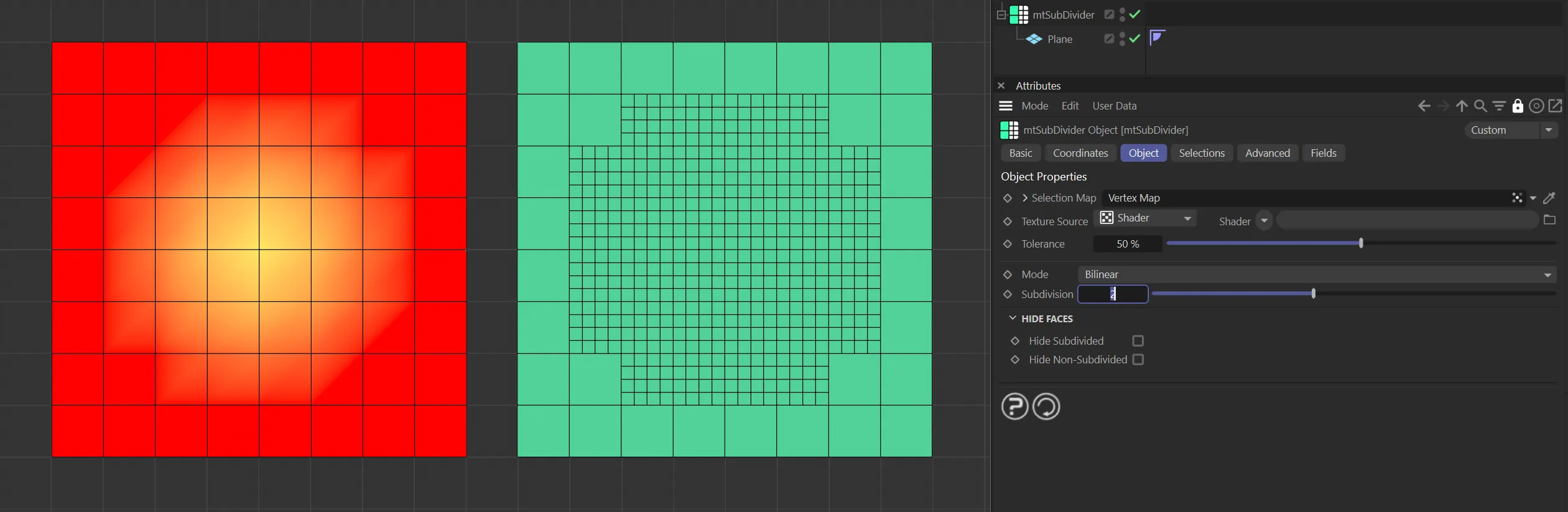
The Plane on the left has a vertex map, which is displayed in the viewport. An identical Plane is on the right, as a child of a mtSubdivider. The vertex weights are driving the subdivisions.
Texture Source
Section titled “Texture Source”You can use shaders, images and even animated video sequences to control where subdivisions are generated.
There are two options: Shader and Texture Tag.
Both use color value to define which areas are selected.
Shader mode
Section titled “Shader mode”Shader
Section titled “Shader”Use the Shader drop-down to select an image, sequence or shader.
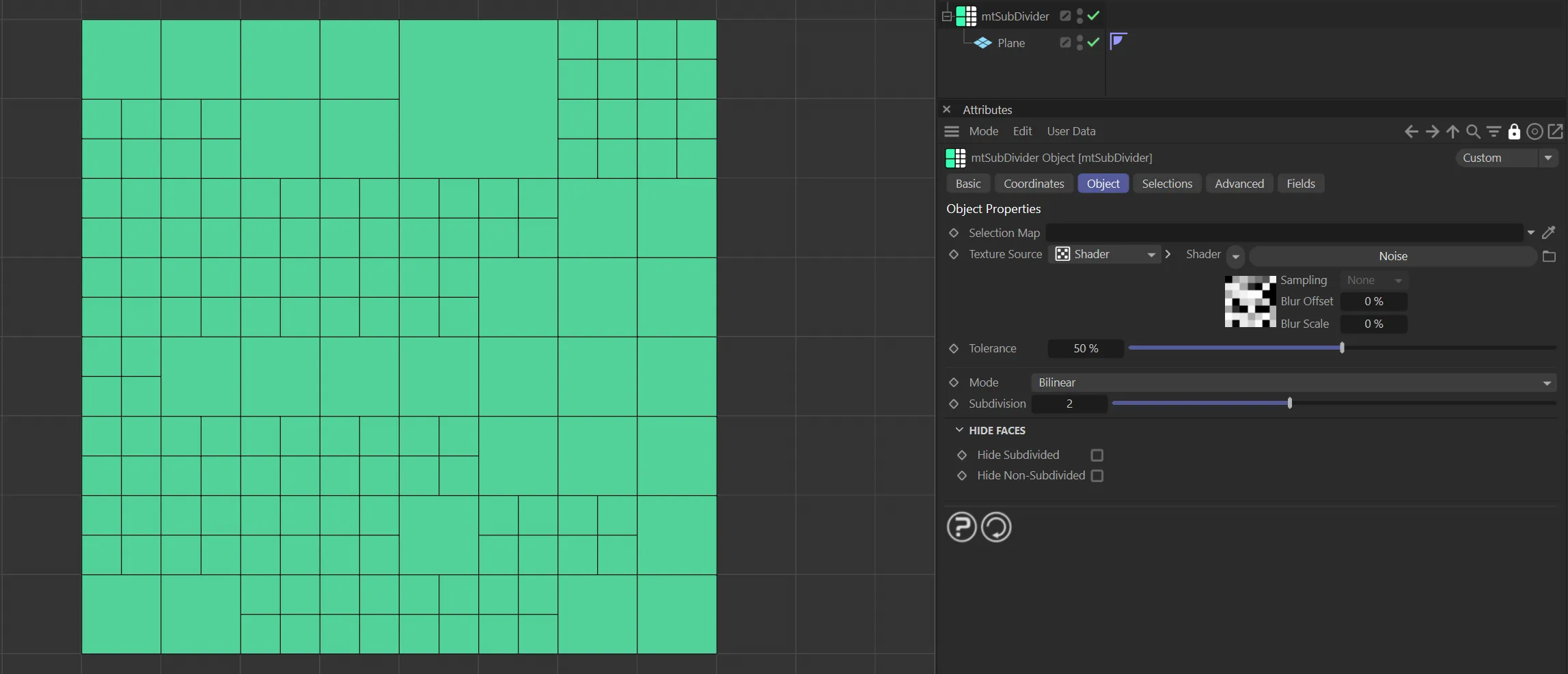
The Noise shader is driving the generated subdivision settings on this Plane.
Texture Tag mode
Section titled “Texture Tag mode”This mode requires a Cinema 4D material.
Place the material on the mtSelect and you will see a texture tag appear alongside it in the Object Manager.
Drag this texture tag into the Texture Tag link field.
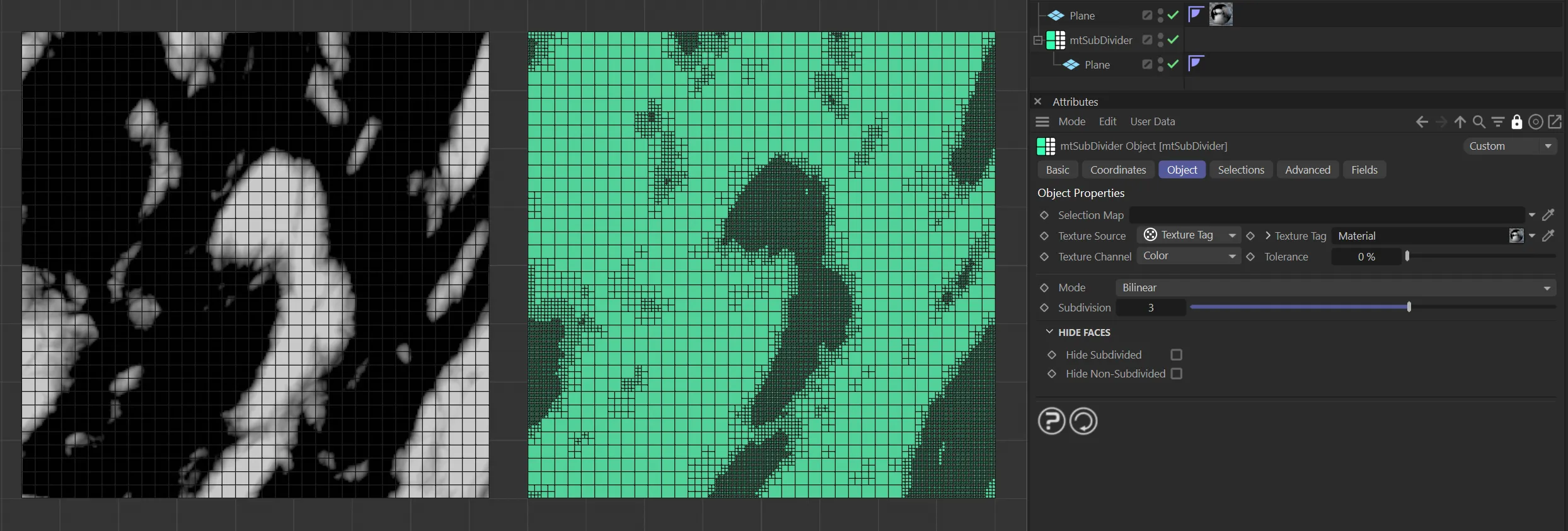
Texture Source set to Texture Tag, with the Noise material on the left driving the subdivision generation on the right-hand Plane.
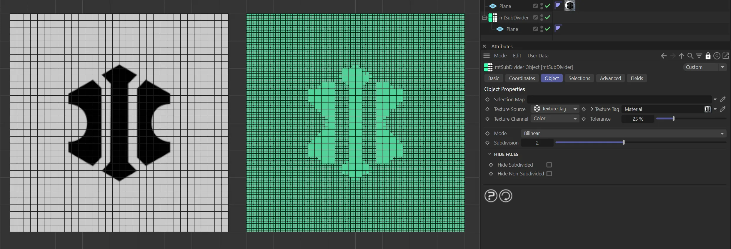
Texture Source set to Texture Tag, with the bitmap material on the left driving the subdivision generation on the right-hand Plane.
Animated video sequence driving the subdivision generation on the right.
Texture Channel
Section titled “Texture Channel”Use the Texture Channel pull-down to select which material channel you wish to reference.
This is set to Color by default.
Tolerance
Section titled “Tolerance”Use the Tolerance slider to adjust the point at which subdivisions are made.
Lower tolerance values will allow darker areas to be subdivided. Higher tolerance values will allow only lighter areas to be subdivided.
Demonstration of the effects of the Tolerance slider with a Noise shader.
Set as Bilinear, by default; this was the previous standard setting.
The alternative subdivision types are: Bilinear Offset, Catmull-Clark, Shards and Whirl.
Bilinear Offset
Section titled “Bilinear Offset”Bilinear Offset mode, as the name suggests, is normal bilinear surface subdivision with the ability to offset the division parameters across the respective axes.
A normal linear surface subdivision occurs, then you can select a local axis to offset in the Axis Offset section, which only becomes available with this mode.
This choice having been made, you can apply the offset strength, control this strength and construct new polygons, potentially all of different sizes.
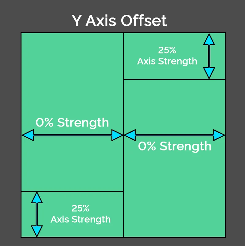
This diagram shows a representation of Bilinear Offset mode, with a Strength of 0 (zero) % but a 25% Axis Offset on the Y axis.
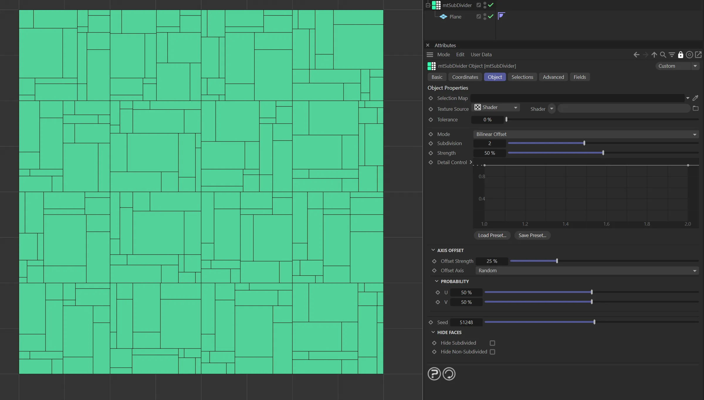
This image shows Bilinear Offset mode, with a Strength of 50 % and a 25% Offset Strength.
Catmull-Clark
Section titled “Catmull-Clark”The Catmull-Clark subdivision surface algorithm, introduced by Edwin Catmull and Jim Clark, is a widely utilised technique for creating smooth surfaces through recursive subdivision of polygonal meshes.
The process can be described in four steps applied at each subdivision level.
Vertex Creation: For each face of the mesh, a new ”face vertex” is generated at the centroid, contributing to the eventual smoothing by averaging the positions of the original vertices of the face.
Edge Splitting: Each edge of the mesh is split by introducing a new ”edge vertex,” computed as the average of the two original vertices and the newly-created adjacent face vertices.
Vertex Updating: The original vertices are updated based on their neighboring original vertices and the surrounding face vertices; the calculation takes into account the original vertex position, the average of the adjacent edge midpoints and the centroid of adjacent faces, with the weights determined by the valence (the number of connecting edges) of the vertex.
Face Division: Each original face is subdivided into new faces by connecting the new face, edge and updated original vertices, thus increasing the density of the mesh/surface.
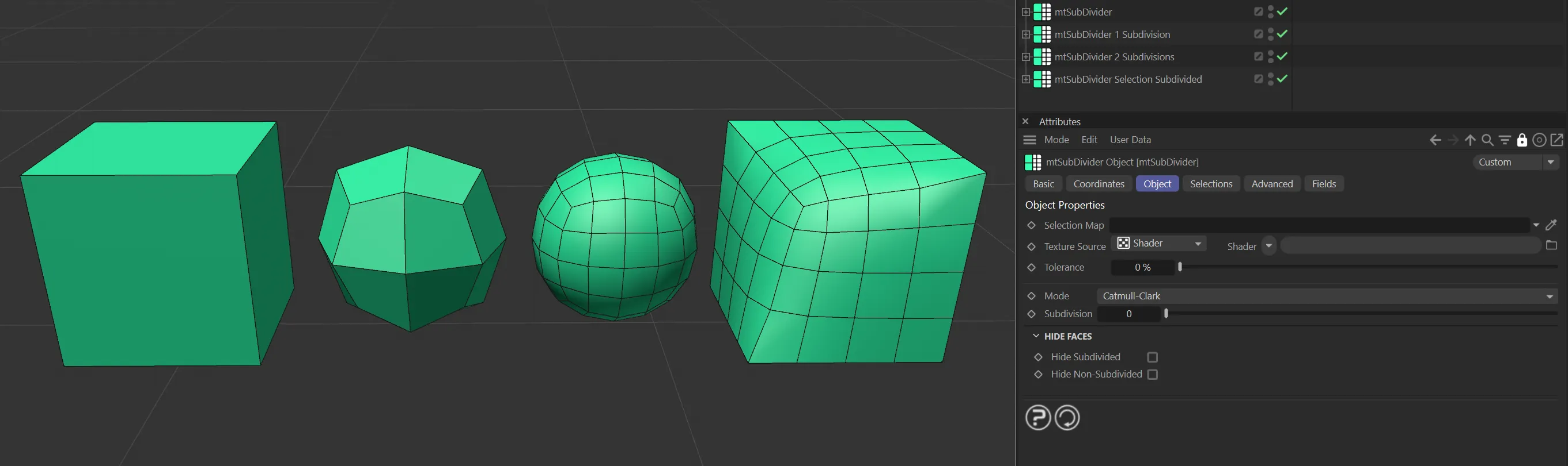
Catmull-Clark mode, displaying various levels of subdivisions. From left to right: undivided, one recursion, two recursions, and three recursions with a polygon selection tag.
Shards
Section titled “Shards”Shards mode works much like the standard bilinear subdivision – it calculates the half edges, puts in a centroid vertex and connects them up.
The Strength parameter then has an effect on the vertex point, producing somewhat interesting surface geometry.
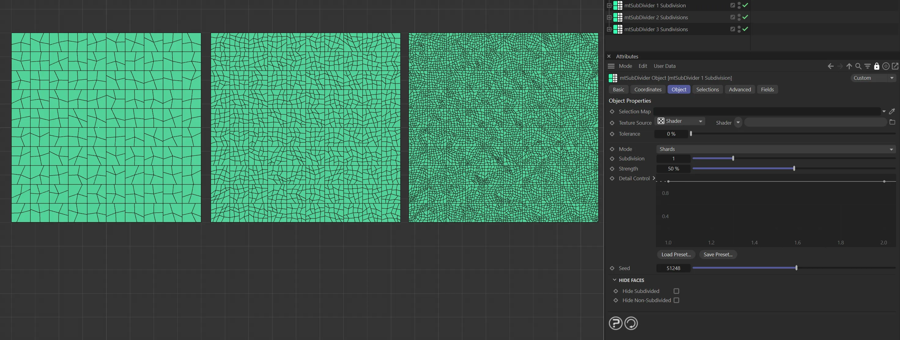
Shards mode, with three levels of Subdivision set, each at 50% Strength. From left to right: one recursion level, two recursion levels and three levels of recursion with a polygon selection tag.
Differing from the other subdivision surface methods, Whirl mode generates (FaceEdges+1) faces on a per original face.
This is four (or three for a triangle) outer faces and a center face, as illustrated below.
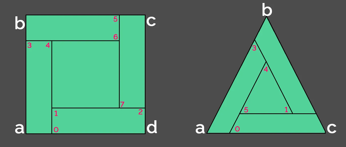
Whirl mode division type representations.
The outer faces are designed to look like they are interweaving, displaying behavior somewhat akin to that of a whirlpool.
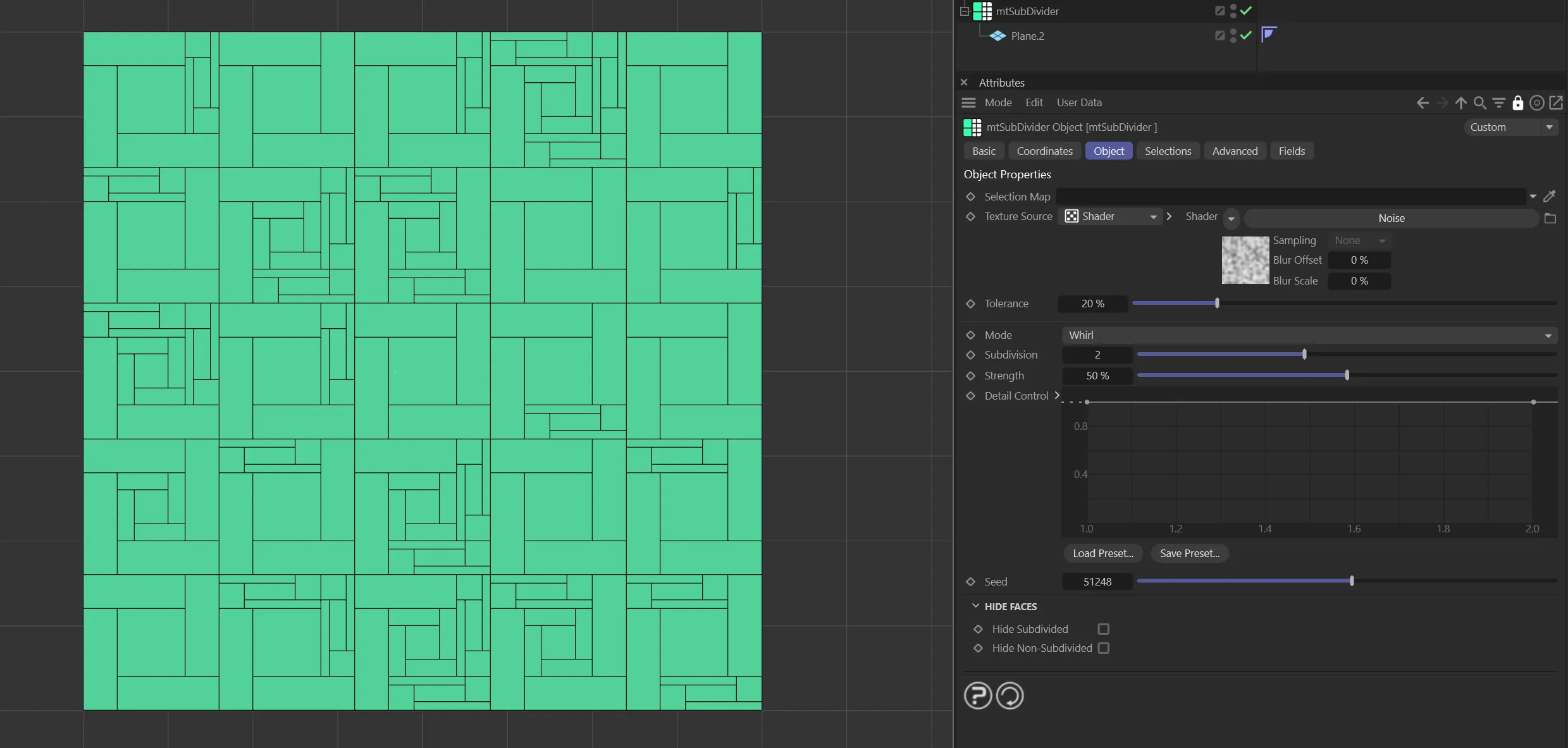
mtSubDivider in Whirl mode, with the Subdivision setting of 2 driven by a noise.
Subdivision
Section titled “Subdivision”You can set multiple levels of subdivision by using this slider.
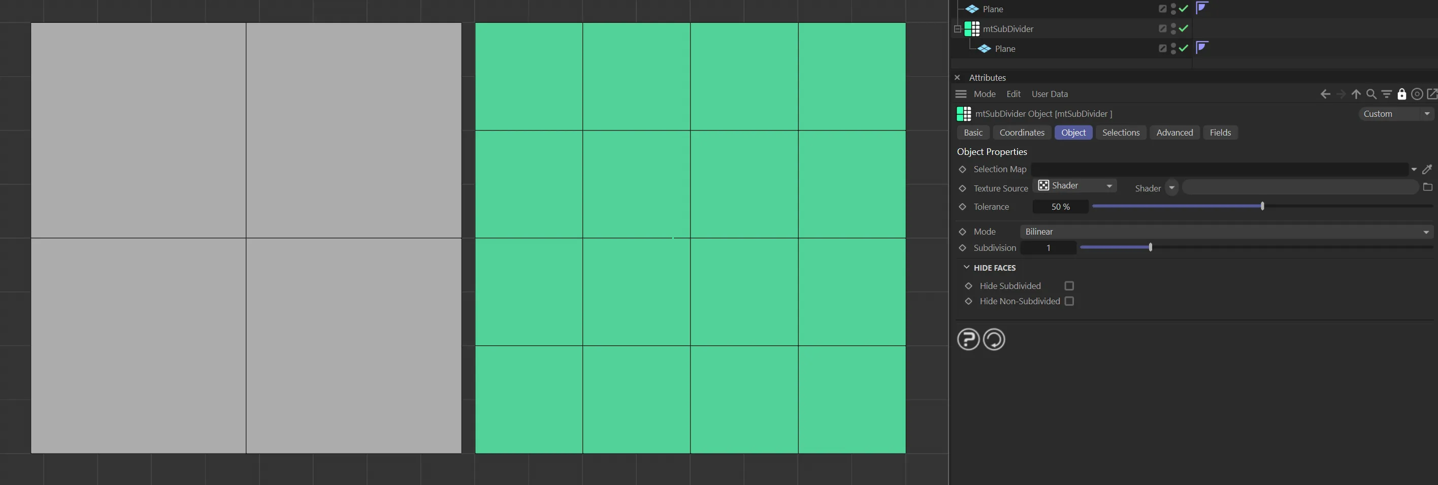
mtSubDivider Subdivision is set to 1. The base mesh has four polygons and the generated mesh has sixteen.
Strength
Section titled “Strength”Available for the Bilinear Offset, Shards and Whirl modes.
This allows extra control and the strength can be modified via a spline on a per-subdivision basis.
The knots on the spline (locked on the x-axis) are automatically added when the level of recursion is increased.
The spline’s view/bounds will automatically resize as needed when the Subdivision value is changed.
Detail Control
Section titled “Detail Control”Available for the Bilinear Offset, Shards and Whirl modes, this is a spline control for the Strength parameter.
Available for the Bilinear Offset, Shards and Whirl modes to add different, random ‘looks’, based on the settings.
Axis Offset
Section titled “Axis Offset”Only available with the Bilinear Offset mode, this gives you the option to apply an offset to the chosen axis.
Offset Strength
Section titled “Offset Strength”This slider applies an offset to the chosen axis by weighting the reference centroid to that side.
This animation shows mtSubDivider in Bilinear Offset mode, demonstrating the Offset Strength parameter.
Offset Axis
Section titled “Offset Axis”Choose a local axis to offset: U, V or per-face Random.
Probability
Section titled “Probability”Also only present in the Bilinear Offset mode, these sliders allow the user to give a weighting to a particular axis.

Probability parameter options.
Controls the weighting of the offset in the u-axis.
Controls the weighting of the offset in the v-axis.
This animation illustrates the effect of the probability weighting in the U and V axes.
Hide Faces
Section titled “Hide Faces”There is the option to change the scene geometry further by hiding polygons, which you have subdivided, to give an interesting look.
Hide Subdivided
Section titled “Hide Subdivided”Subdivided polygons are hidden.
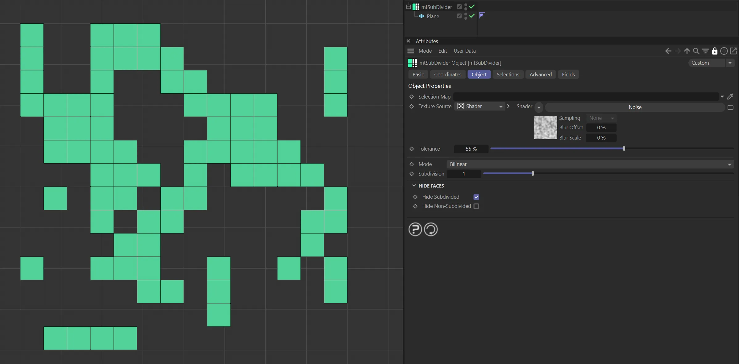
This Plane has Hide Subdivided enabled.
Hide Non-Subdivided
Section titled “Hide Non-Subdivided”Non-subdivided polygons are hidden.
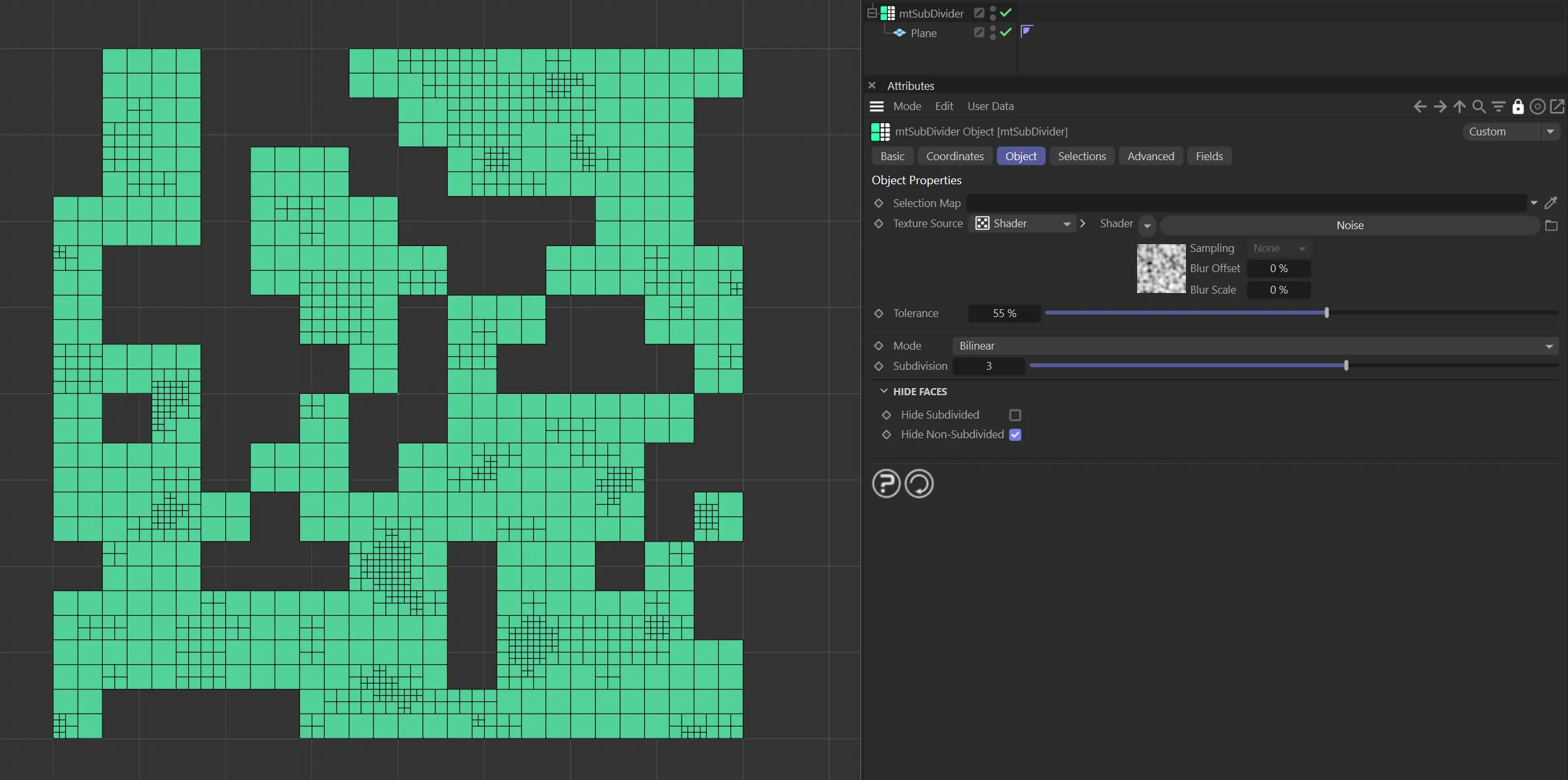
This Plane has Hide Non-Subdivided enabled.
Selections tab
Section titled “Selections tab”You can create polygon selections based on the mtSubdivider operation.
Each selection is stored within a selection tag, which is automatically generated on activation.
Selections can be visualized by activating Display Selection.
You can change the color of the displayed selection using the color picker.
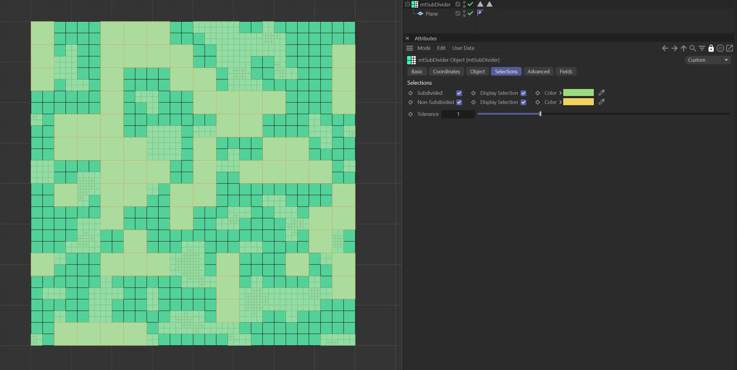
Plane subdivisions visualized in the Selections tab color options.
Subdivided
Section titled “Subdivided”Create a polygon selection from subdivided topology.
Non-Subdivided
Section titled “Non-Subdivided”Create a polygon selection from any remaining base-mesh topology.
Advanced tab
Section titled “Advanced tab”Optimize
Section titled “Optimize”Newly generated topology can include duplicated points and surfaces.
These can be eliminated by selecting Optimize.
Polygons
Section titled “Polygons”One or two point surfaces will be eliminated.
Unused Points
Section titled “Unused Points”Any unused points will be deleted.
Points
Section titled “Points”Duplicated points will be eliminated.
Tolerance
Section titled “Tolerance”Duplicated points are merged if they are within the Tolerance range setting.
Fields tab
Section titled “Fields tab”You can use the Fields options to control where mtSubDivider operates.
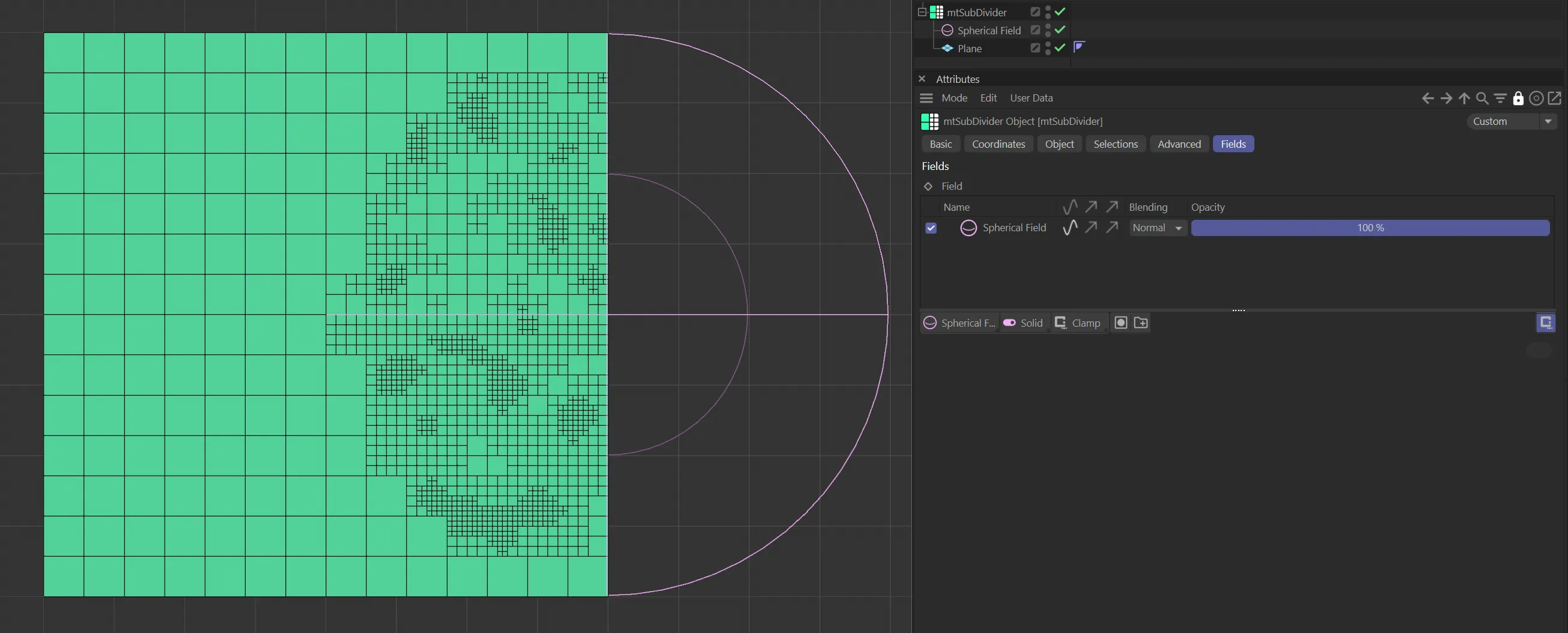
A Spherical Field is being used to subdivide polygons.
Copyright © 2026 INSYDIUM LTD. All rights reserved.