mtRayline
mtRayline generates rays from a starting point, casts them out into the scene and collides them off chosen objects.
Rays can also be cast to bounce within an object’s volume.
Splines are generated from the rays and can be animated.
Object tab
Section titled “Object tab”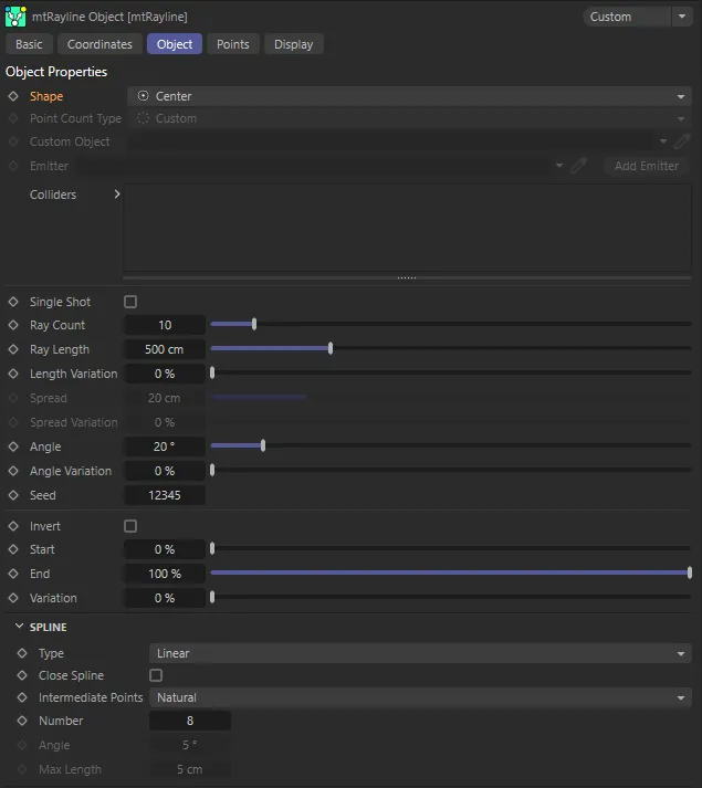
mtRayline User Interface (UI) menu.
Set as Center, by default, this changes the distribution of the starting points for the rays.
The alternatives are: Circle, Line, Custom Object and X-Particles.
Center
Section titled “Center”All rays start at the same central point.
Shape set as Center, with rays starting at the same central point.
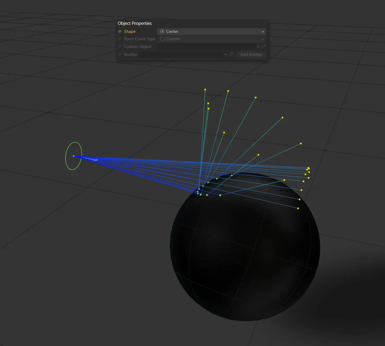
Circle
Section titled “Circle”Rays start from the same point, offset by a radial value, controlled by the Spread settings.
Shape is set as Circle here, with rays in a radial pattern.
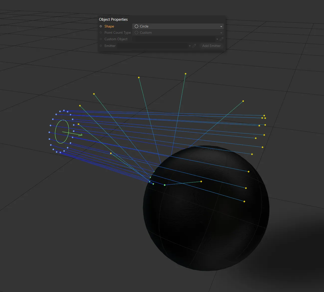
Rays start equally-spaced along a row, controlled by the Spread settings.
Shape in the Line setting.
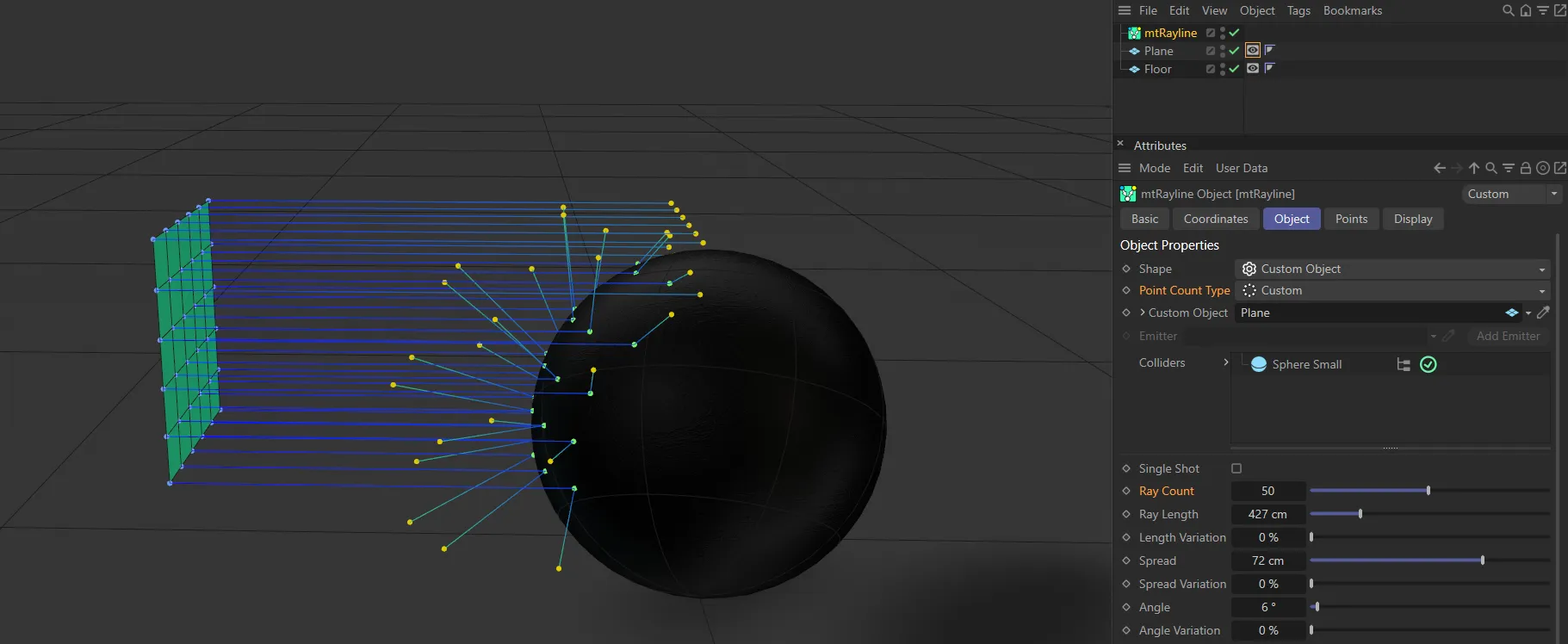
Custom Object
Section titled “Custom Object”Rays start from points of the object in the Custom Object field.
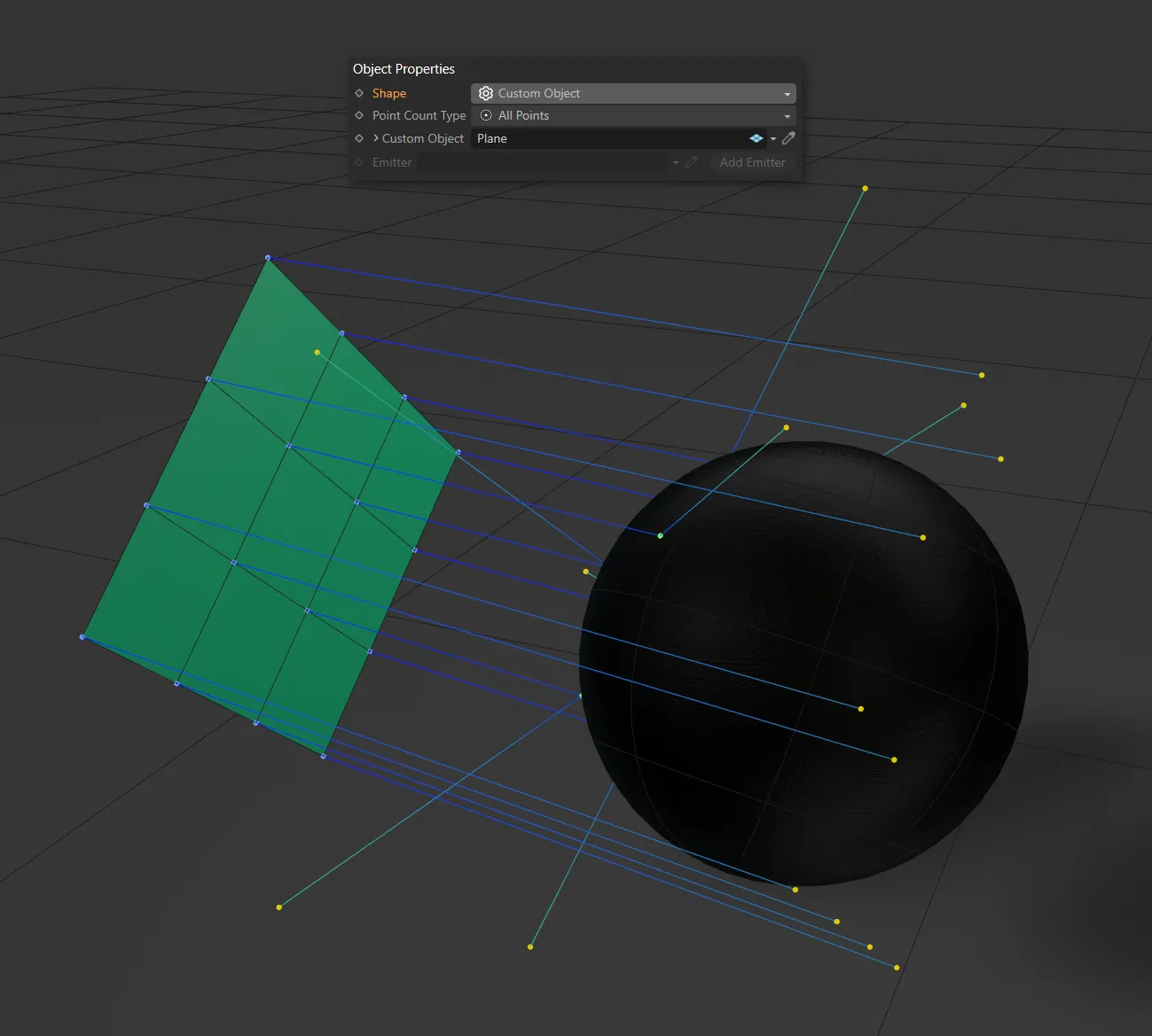
Here, the Shape setting is Custom Object, with a Plane in the Custom Object field.
X-Particles
Section titled “X-Particles”For this setting to work, there must be an emitter in your scene.
You can either drop an emitter into the Emitter field or add an emitter by clicking the Add Emitter button.
Rays will then begin from particles emitted.
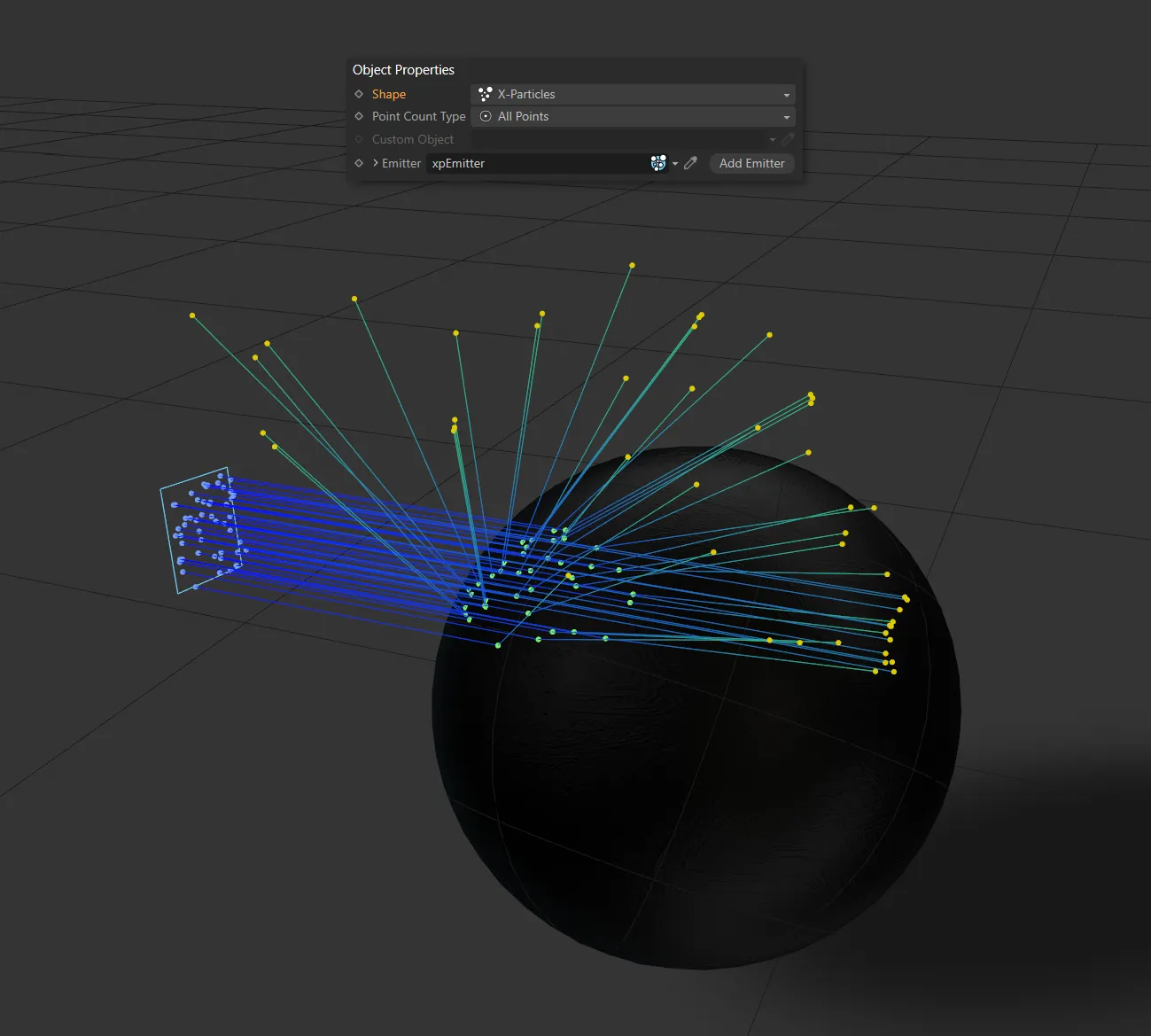
The Shape setting of X-Particles, with rays being emitted from the xpEmitter, in the Emitter field.
The mtRayLine object must exist within the volume of a linked collider object.
Rays will then bounce in the inside of the collider mesh, as in the image below.
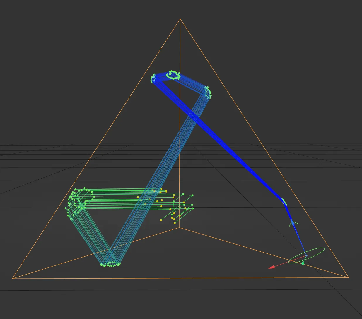
The mtRayline object is inside this Platonic, with a Shape setting of Center and a Ray Count of 25.
Point Count Type
Section titled “Point Count Type”Only available in the Shape settings of Custom Object and X-Particles.
Set as Custom, by default, this has a different control over where the rays originate, based on the point count in the geometry mesh and the Ray Count value.
A ray count generates rays, starting from the first points and increasing the ray count increases the amount of rays until all points are generating rays.
With an emitter. low ray count generates rays from the first particles born; if there are 100 particles but the Count Type is set to Custom Point with a ray count of 5, only the first 5 of 100 particles will generate rays.
The alternative setting is All Points.
Custom
Section titled “Custom”Dependent on the Ray Count value, this gives you control over the pattern of the rays’ emission.
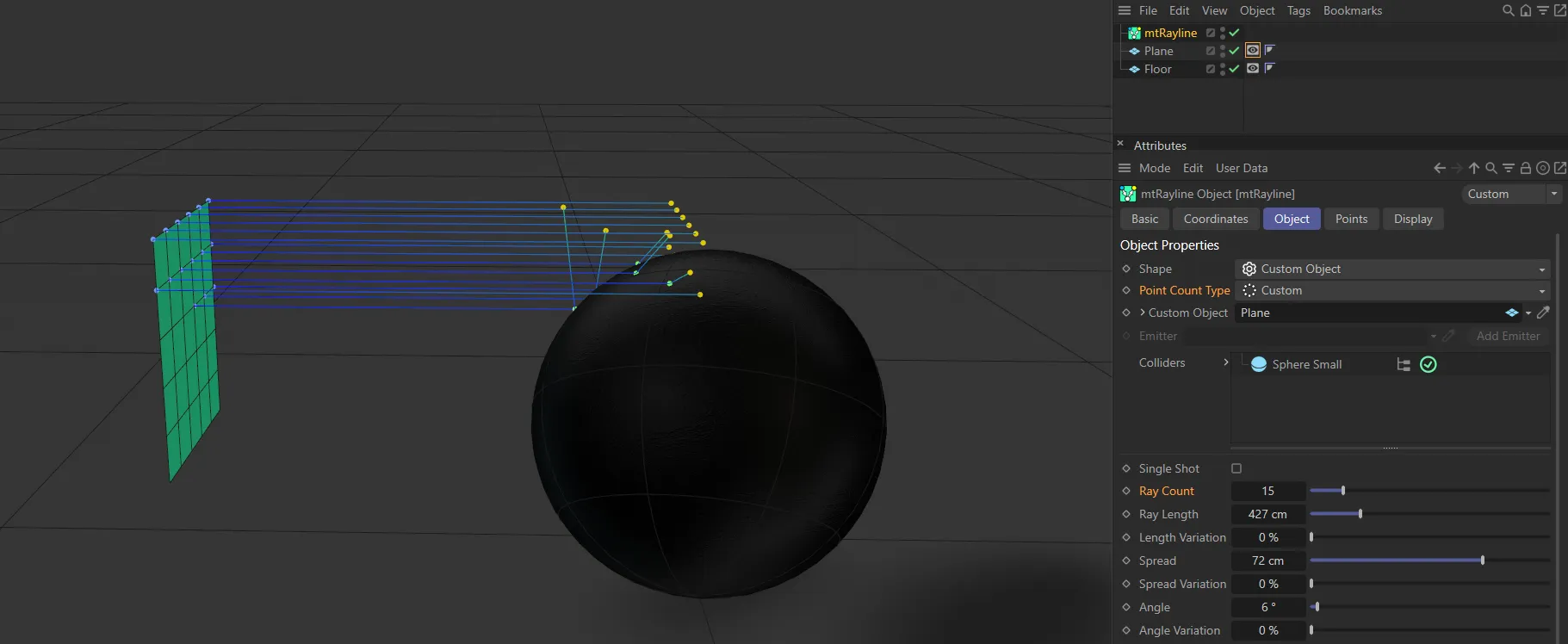
In this image, the Point Count Type is Custom, with a Ray Count value of 15 coming from the Custom Object, which is a Plane.
The same settings as above, but the Ray Count has been increased to 50.
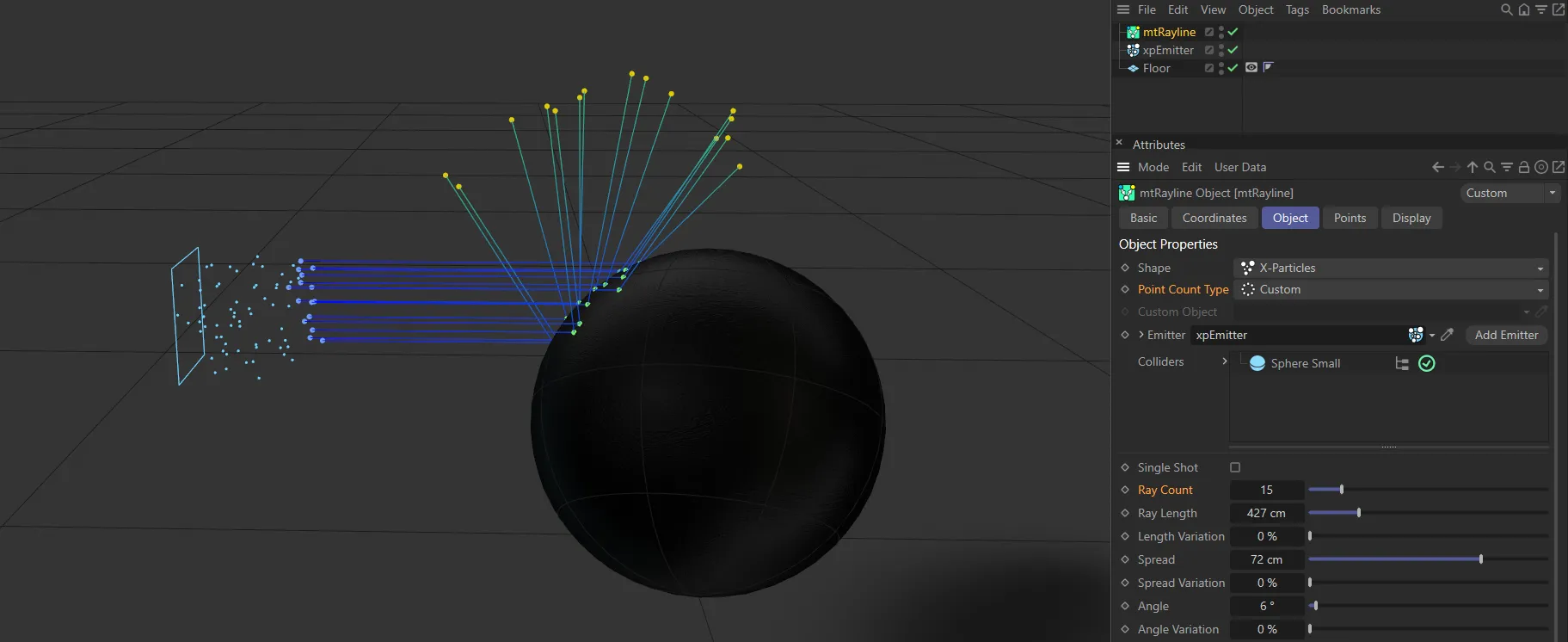
Here the Shape is X-Particles, with particles being emitted. There is a Point Count Type of Custom and a Ray Count of 15, so rays are being generated only from the first 15 particles.
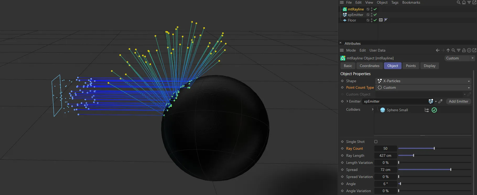
Identical settings as above, except the Ray Count is increased to 50.
All Points
Section titled “All Points”Rays will be emitted from every point on your object or every particle emitted, depending on whether the Shape setting is Custom Object or X-Particles.
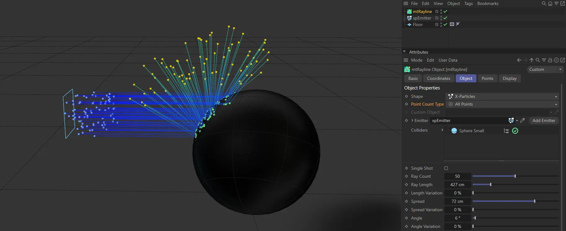
With the Point Count Type of All Points, every particle emitted here is creating a ray.
Custom Object
Section titled “Custom Object”Only available when the Shape setting of Custom Object is selected.
Drop your polygon object into this field to make it the origin of your rays.
Alternatively, use the eye-dropper tool to select an object in your scene.
Clicking on the drop-down arrow next to the parameter will give you access to the Cinema 4D Object tab settings for your object.
Emitter
Section titled “Emitter”Only available when the Shape setting of X-Particles is selected.
Drop your emitter into this field to make particles the origin of your rays.
Add Emitter
Section titled “Add Emitter”Click this button to add a new emitter to your field.
Colliders
Section titled “Colliders”Any item(s) dragged and dropped into this list will become a collider for rays which are in its path.
Items can be disabled by clicking the green arrow (turning it into a red cross) and then rays will simply pass through them.
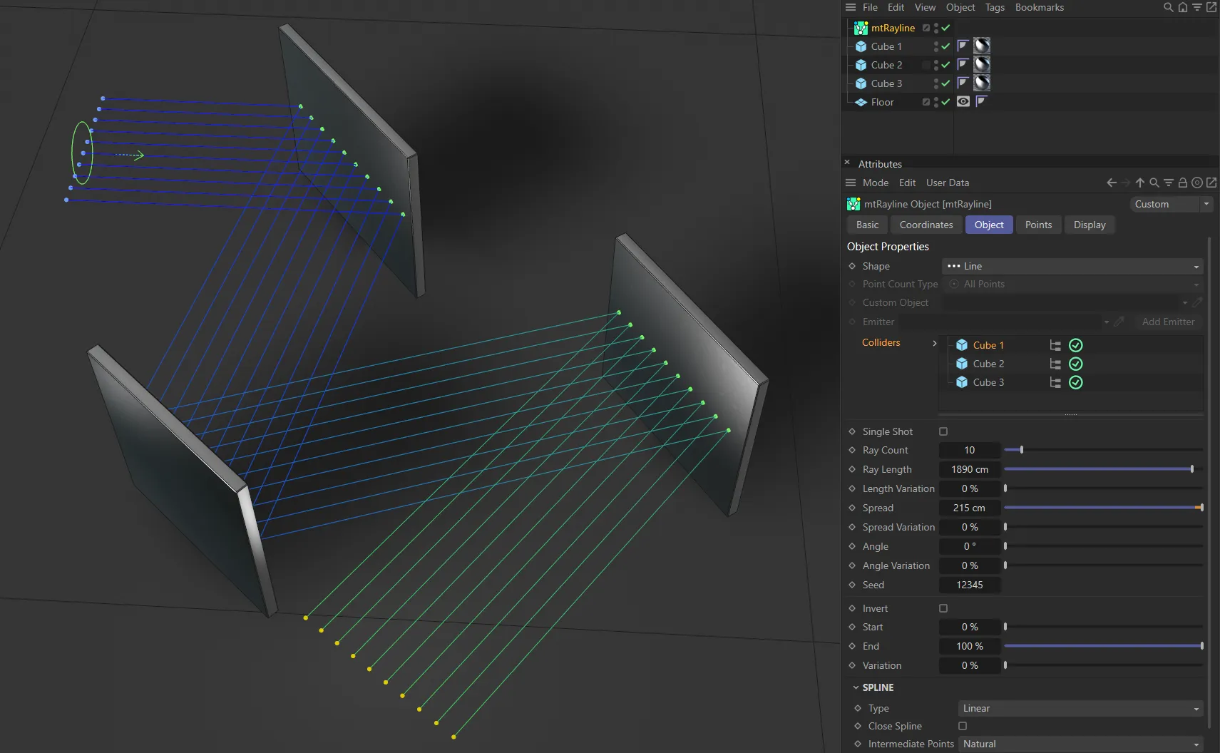
The three Cubes in this scene are all enabled in the Colliders list and rays are bouncing off them.
Single Shot
Section titled “Single Shot”If disabled, rays will bounce off a surface.
If enabled, rays will stop once it intersects/collides with a filter object.
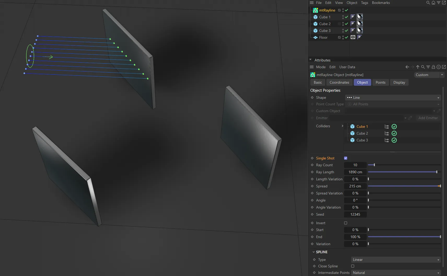
Here, Single Shot is enabled so the rays stop at the first collision, with a Cube primitive.
Ray Count
Section titled “Ray Count”The number of rays being cast.
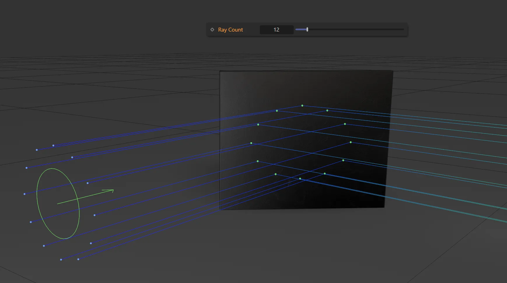
Ray Count value of 12.
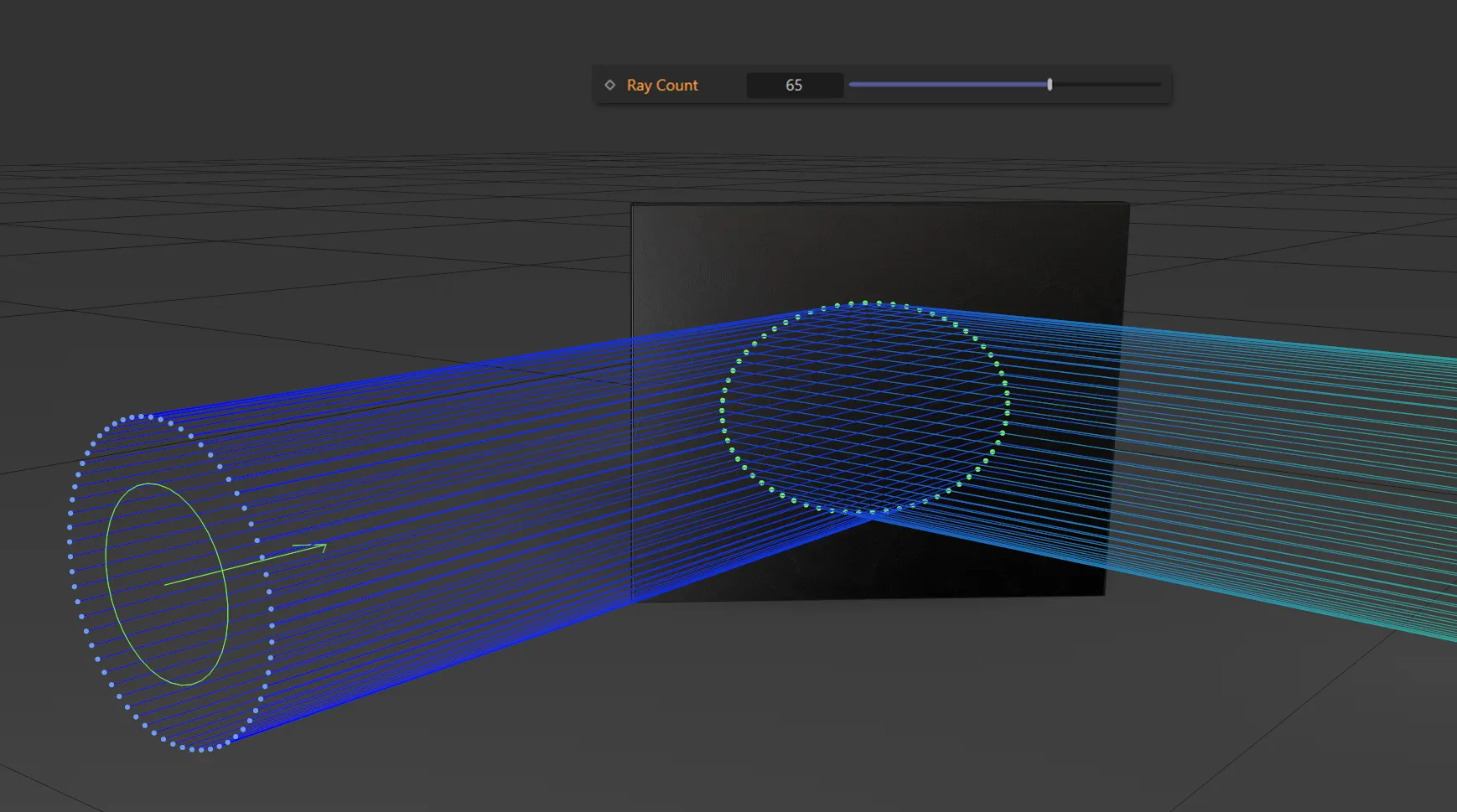
Ray Count increased to 65.
Ray Length
Section titled “Ray Length”The desired length of each ray.
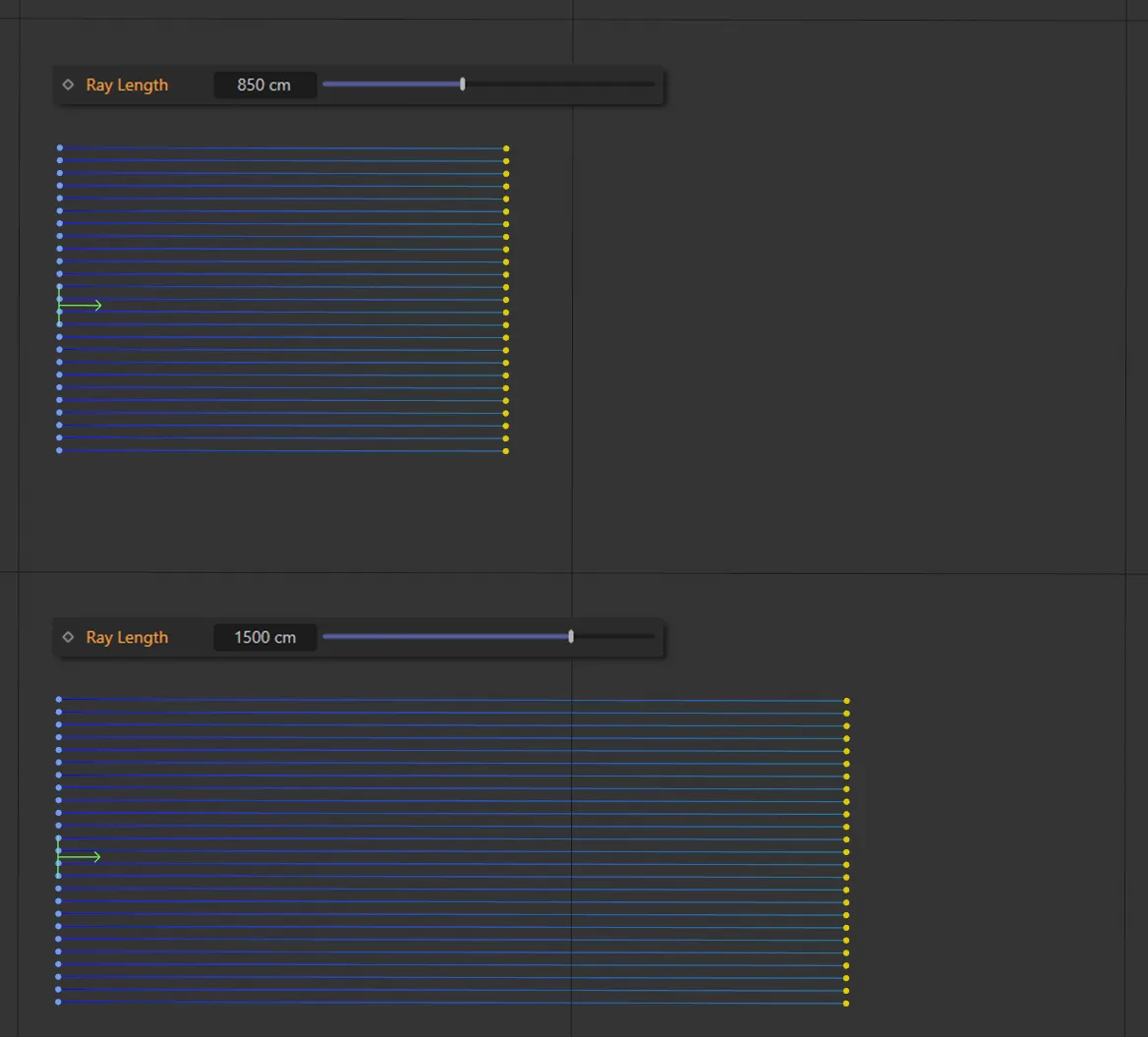
This image shows a Ray Length of 850cm, above, and 1500cm, below.
Length Variation
Section titled “Length Variation”You can add a variation between the length of the rays with this parameter.
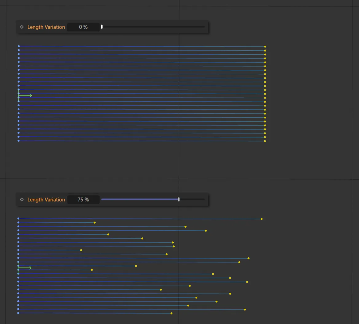
The top has a Length Variation of 0 (zero) % so all rays are the same length. It is raised to 75% below, with clear variety in length.
Spread
Section titled “Spread”If Shape is set to Line or Circle, this is the distance of distribution between the rays’ starting points.
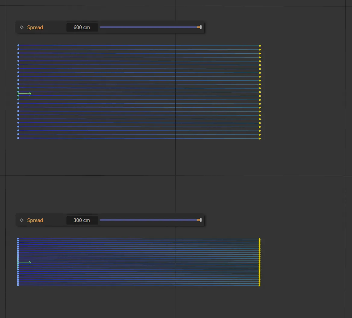
Spread settings of 600cm (top) and 300cm (below).
Spread Variation
Section titled “Spread Variation”Vary the size of spread for each ray, randomly, by this strength.
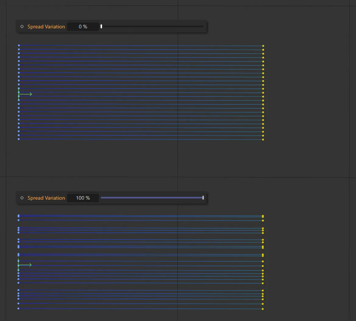
Spread Variation is zero, above, but it is set at 100%, below, giving a different spread setting between each ray line.
The degree by which each ray will offset from the center.
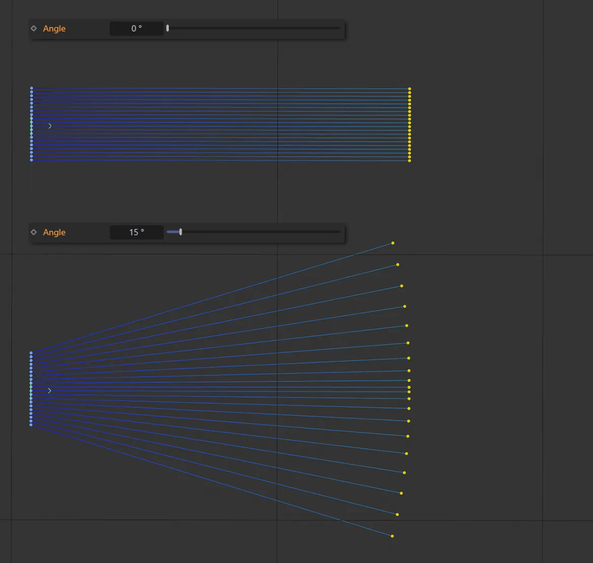
The Angle settings here are 0 (zero) degrees, above, and 15 degrees, below.
Angle Variation
Section titled “Angle Variation”Vary the size of angle for each ray, randomly, by this strength.
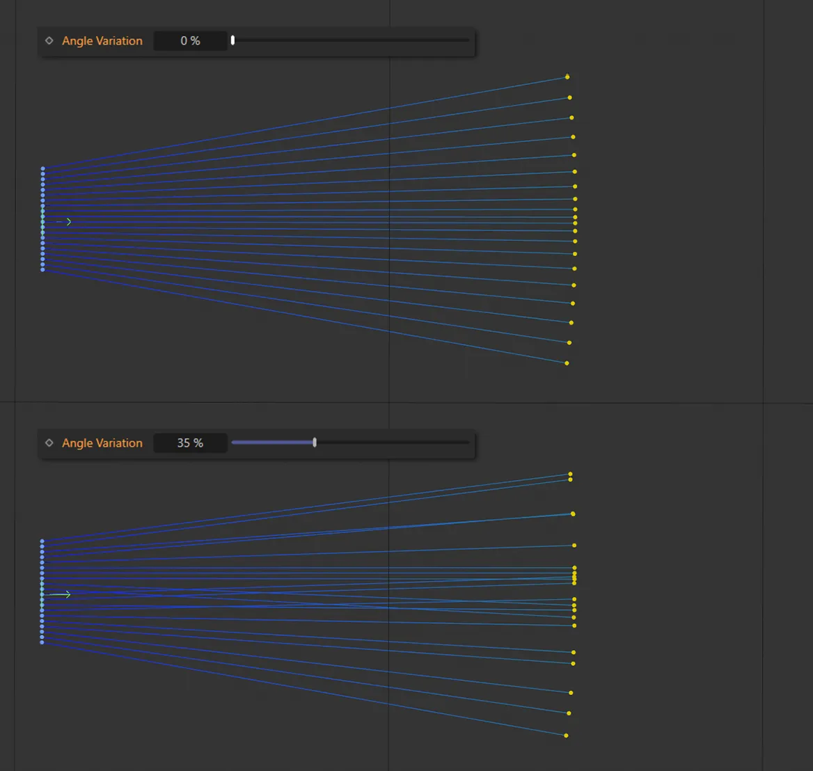
Here there is zero Angle Variation (top) and 35% (bottom) applied.
Give a random value for the ray pattern, dependent on the settings above.
Invert
Section titled “Invert”Ticking this box will invert the following Start and End settings.
Rays will begin at this offset to their original size.
This can be animated for growth effects.
Start is animated here, as it drops from 100% to 0 (zero) % and rays bounce off a rotating scene Pyramid and three Cubes (all set as Colliders).
Rays will end at this offset to their original size.
End is keyframed here, resulting in the rays drawing in from start to end.
Variation
Section titled “Variation”Vary the size of growth for each ray randomly by this strength.
This animation demonstrates a 75% Variation setting on the size of growth for each ray.
Spline
Section titled “Spline”These are the standard Cinema 4D spline options.
Set as Linear, by default, this changes how the spline shape is calculated.
The alternative options are: Akima, Bezier, B-Spline and Cubic.
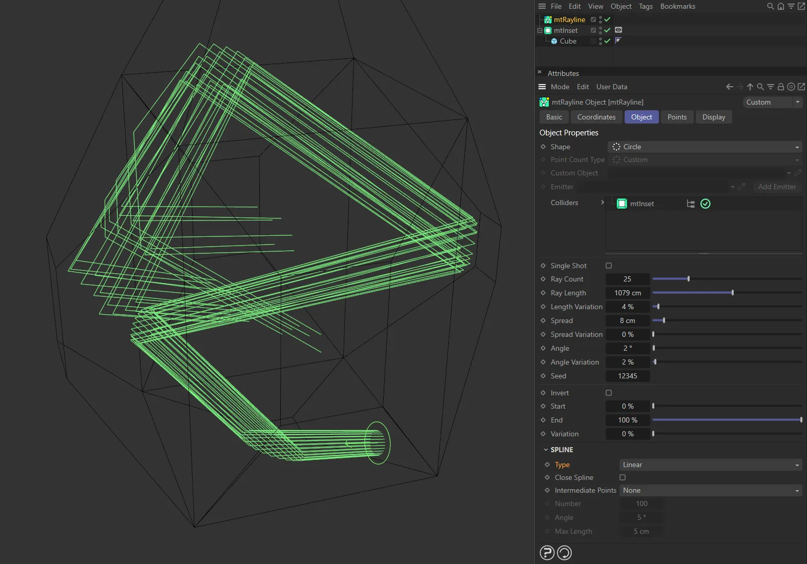
Linear spline Type setting.
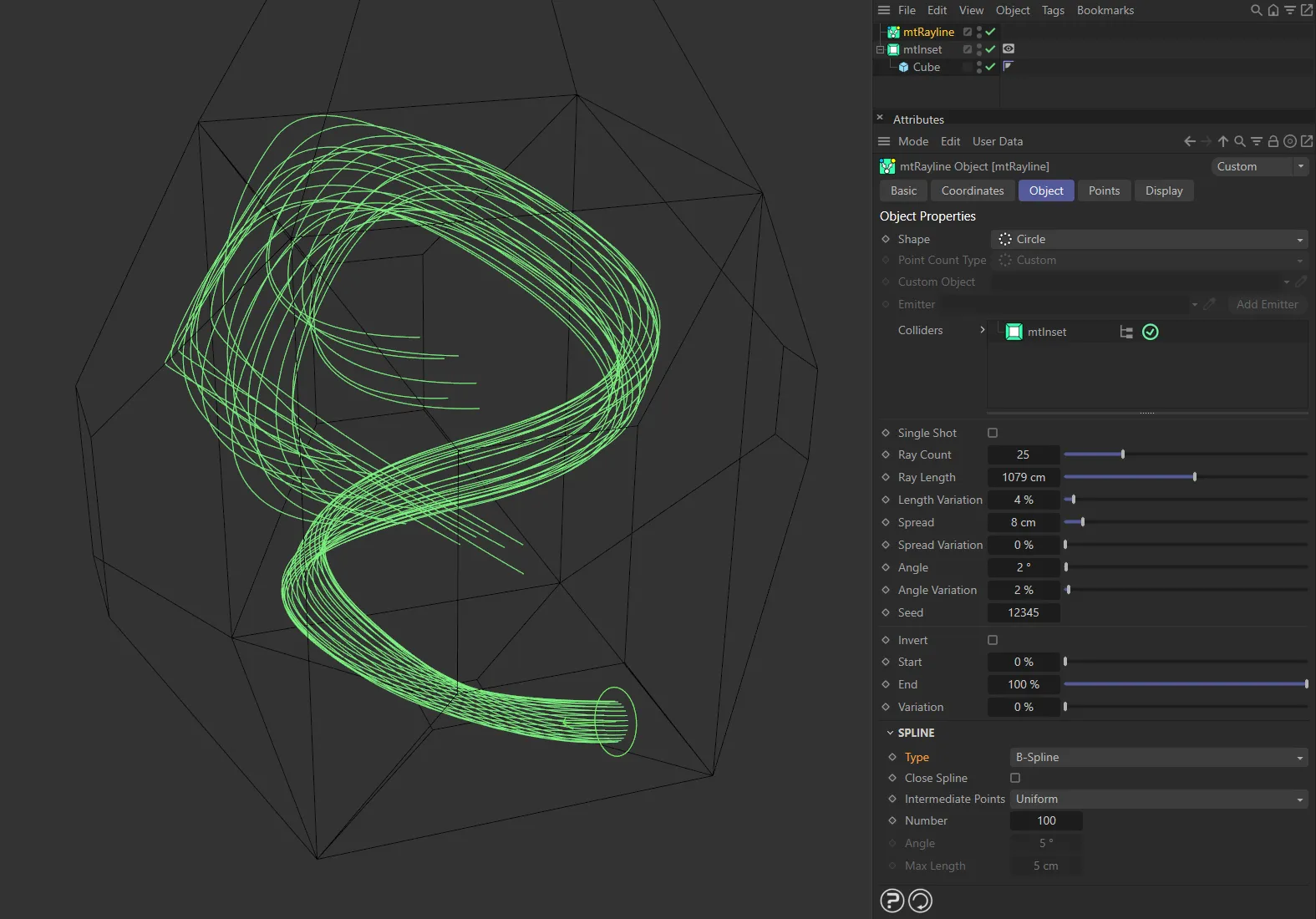
B-Spline setting.
Close Spline
Section titled “Close Spline”Enabling this will create a final section between the first and last points, closing the spline.
Intermediate Points
Section titled “Intermediate Points”Set as Natural, by default, these are the standard Cinema 4D options.
Alternatives are: None, Uniform, Adaptive and Subdivision.
Number, Angle, Max Length
Section titled “Number, Angle, Max Length”These options are relevant to different Type and Intermediate Point selections.
Points tab
Section titled “Points tab”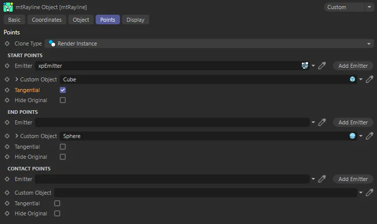
The Points tab UI settings.
The results can be expanded by adding various objects to the start, end and contact points.
Clone Type
Section titled “Clone Type”Set as Render Instance, by default, this changes the type of any polygonal object, which is added as a custom object.
The alternative options are: Polygon, Single Mesh and Multi-Instance.
Start Points, End Points, Contact Points
Section titled “Start Points, End Points, Contact Points”Each of the three points has the same parameters.
Emitter
Section titled “Emitter”Add an emitter here, by dragging and dropping into the field or by clicking the Add Emitter button, to spawn particles at these points.
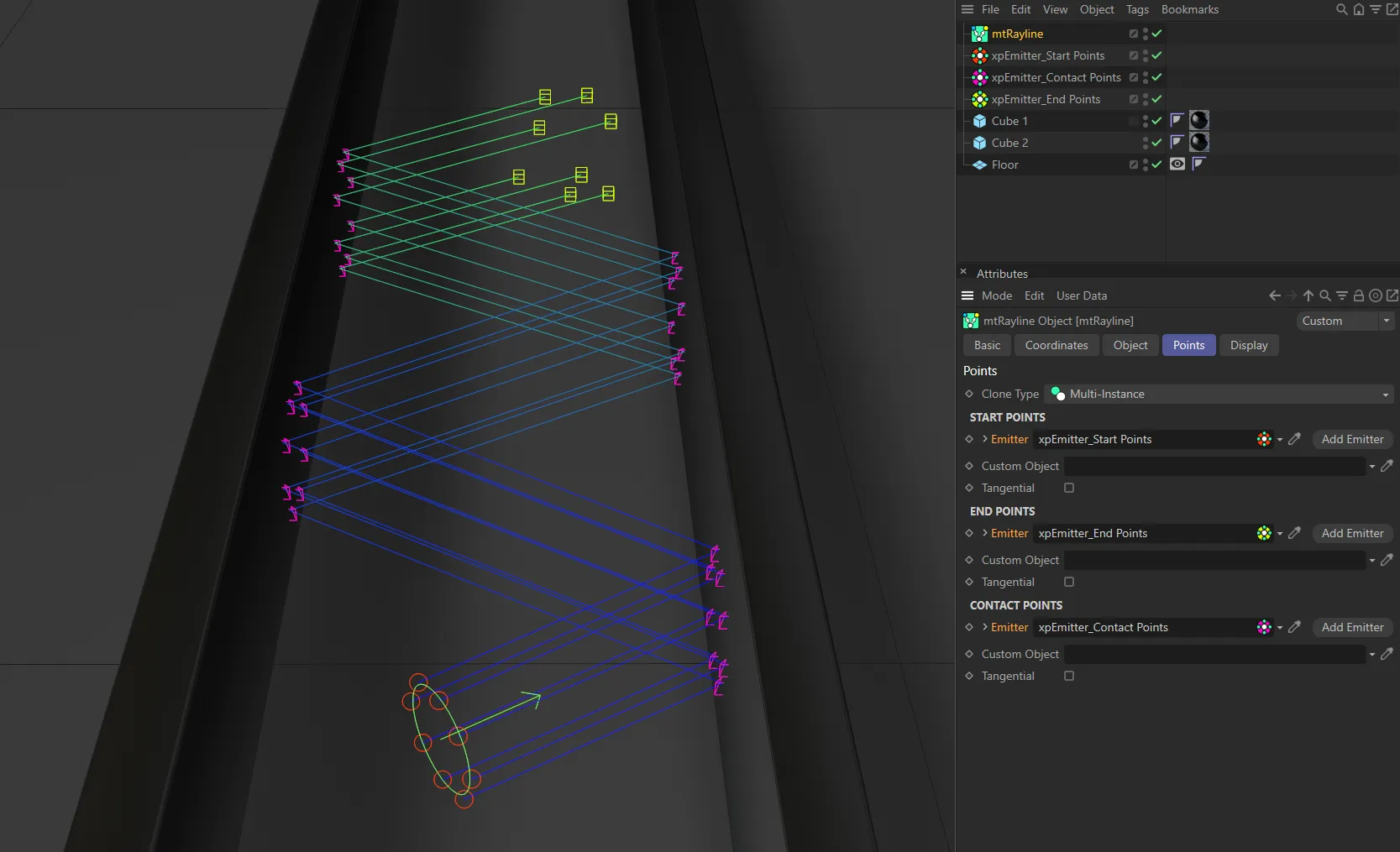
Here, emitters are being used for Start Points, End Points and Contact Points for the rays.
Custom Object
Section titled “Custom Object”Clones a polygon or spline object to each point.
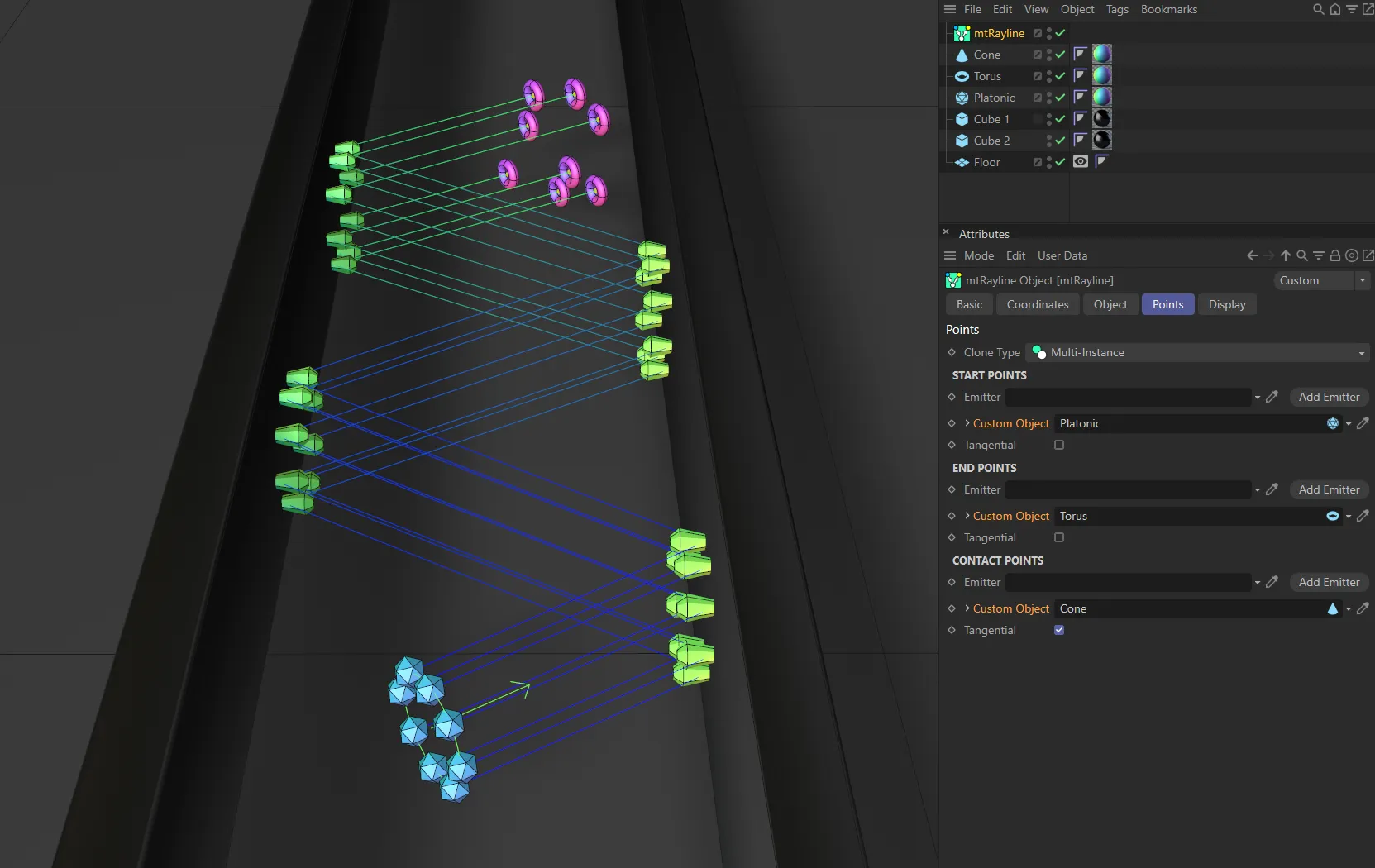
In this image, a Platonic, a Cone and a Torus are being used as Custom Objects for Start Points, Contact Points and End Points respectively.
Clicking on the drop-down arrow next to the parameter will give you access to the Cinema 4D Object tab settings for your object.
Tangential
Section titled “Tangential”Enabling this aligns the new object to face the direction of the ray.
Display tab
Section titled “Display tab”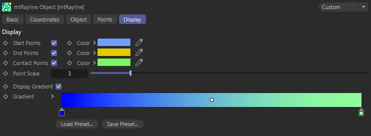
The Display tab UI menu.
These options will change the display of splines and points in your scene.
Display Gradient
Section titled “Display Gradient”This parameter enables the gradient coloring on the splines/rays in the scene.
Copyright © 2026 INSYDIUM LTD. All rights reserved.