tfErosionHydraulic
tfErosionHydraulic simulates the realistic erosion of terrains by precipitation, using one of two modes.
Properties
Section titled “Properties”Hydraulic (2D Particles) is a 2-dimensional simulation and is therefore a much quicker filter, using heightmap information.
Hydraulic (X-Particles) is a 3D particle simulation filter, allowing much more control, but taking longer to simulate.
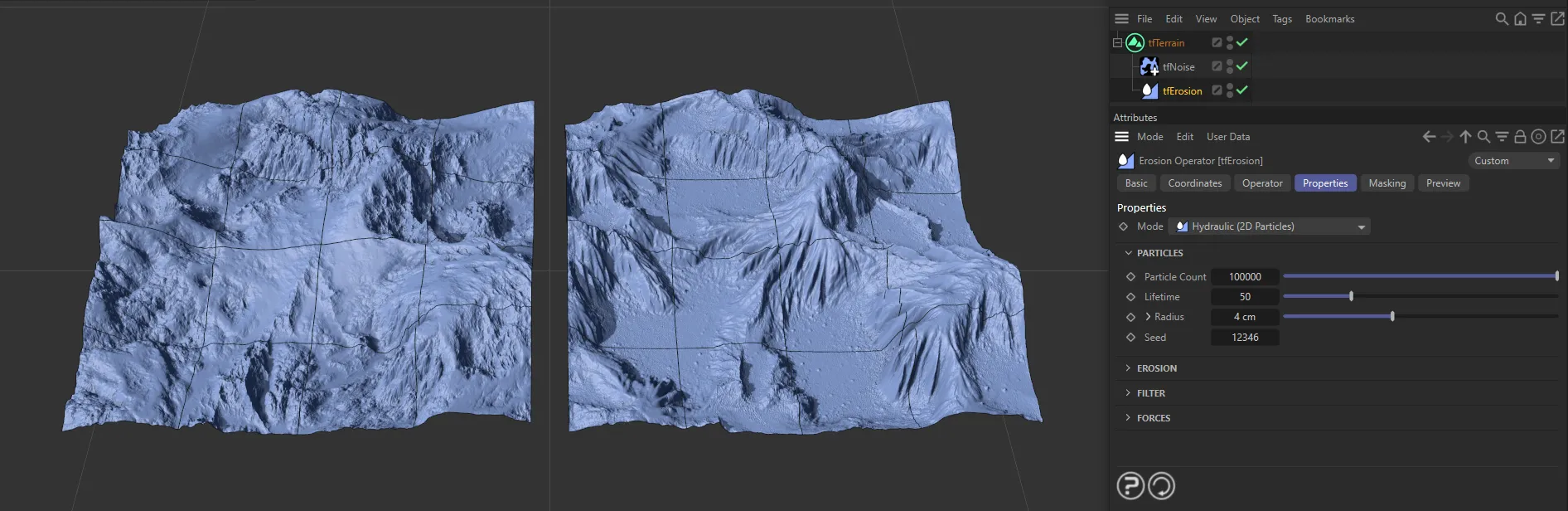
The image on the right shows the immediate effect of tfErosionHydraulic - this is set in Hydraulic (2D Particles) - against the standard Thermal Weathering mode with a tfNoise operator.
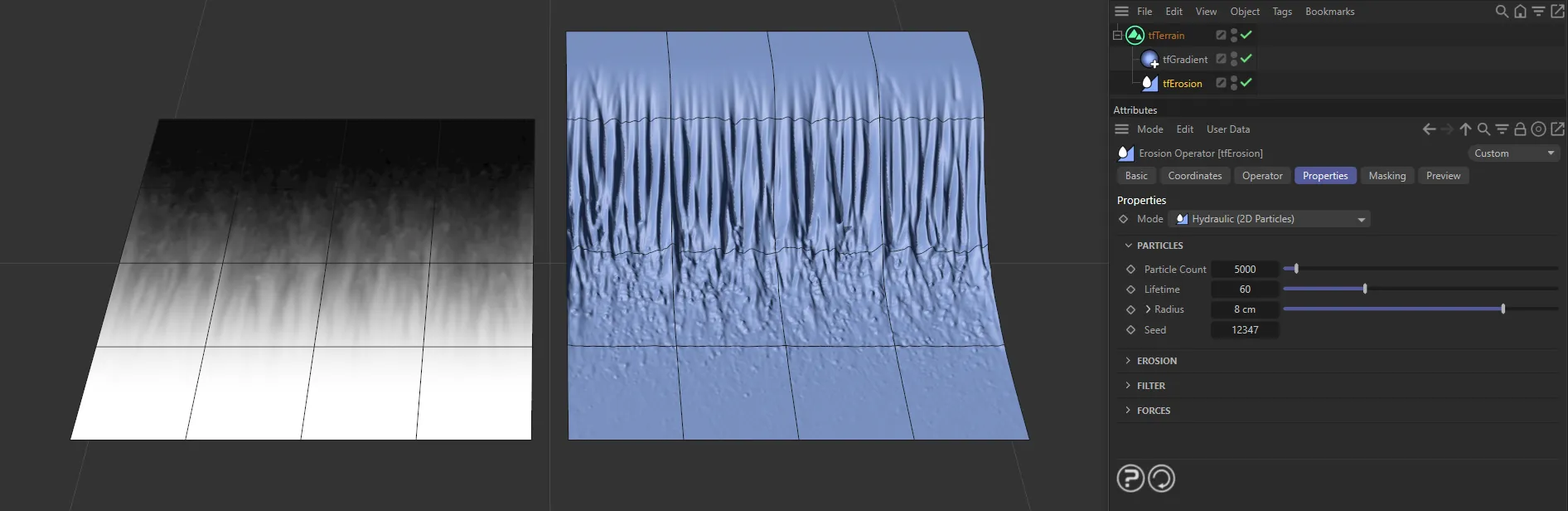
This image shows the effect of tfErosionHydraulic on a Linear mode of the tfGradient filter.
Hydraulic (2D Particles) mode
Section titled “Hydraulic (2D Particles) mode”Particles
Section titled “Particles”Particle Count
Section titled “Particle Count”You can decide how many particles you would like used in the scene.
By default, this Particle Count is set at 10000.
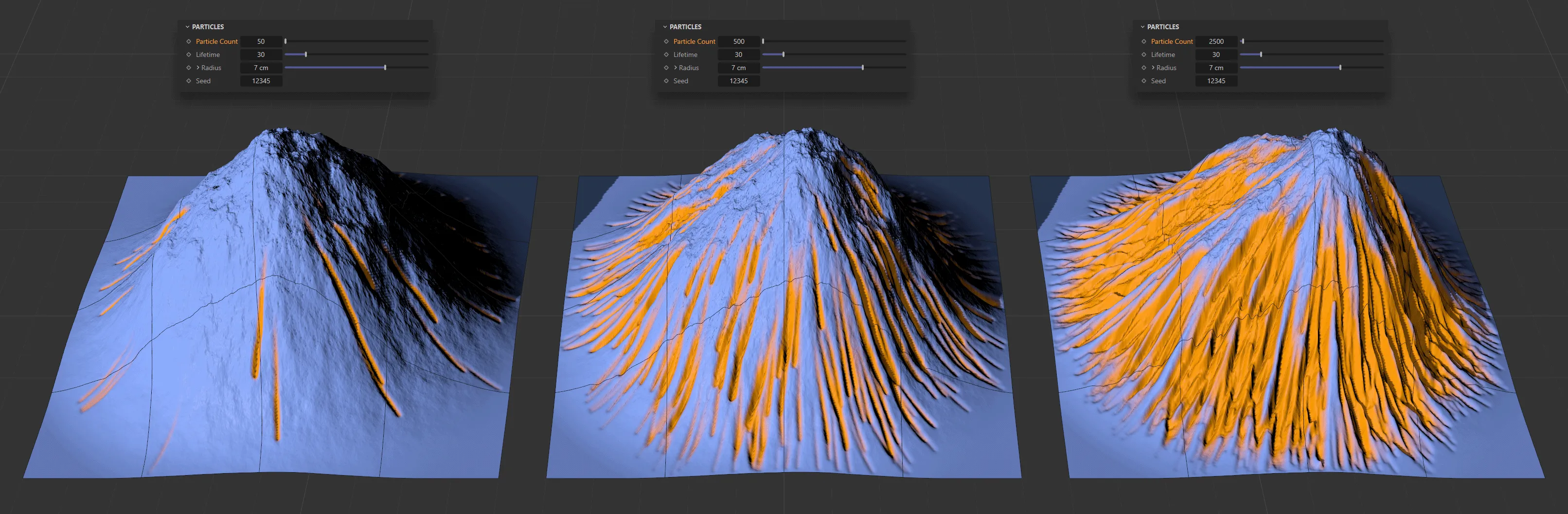
The terrain on the left has a Particle Count of 50, raised to 500 in the center and then at 2500, on the right. All other settings are identical.
Lifetime
Section titled “Lifetime”The lifespan of the particles, in frames.
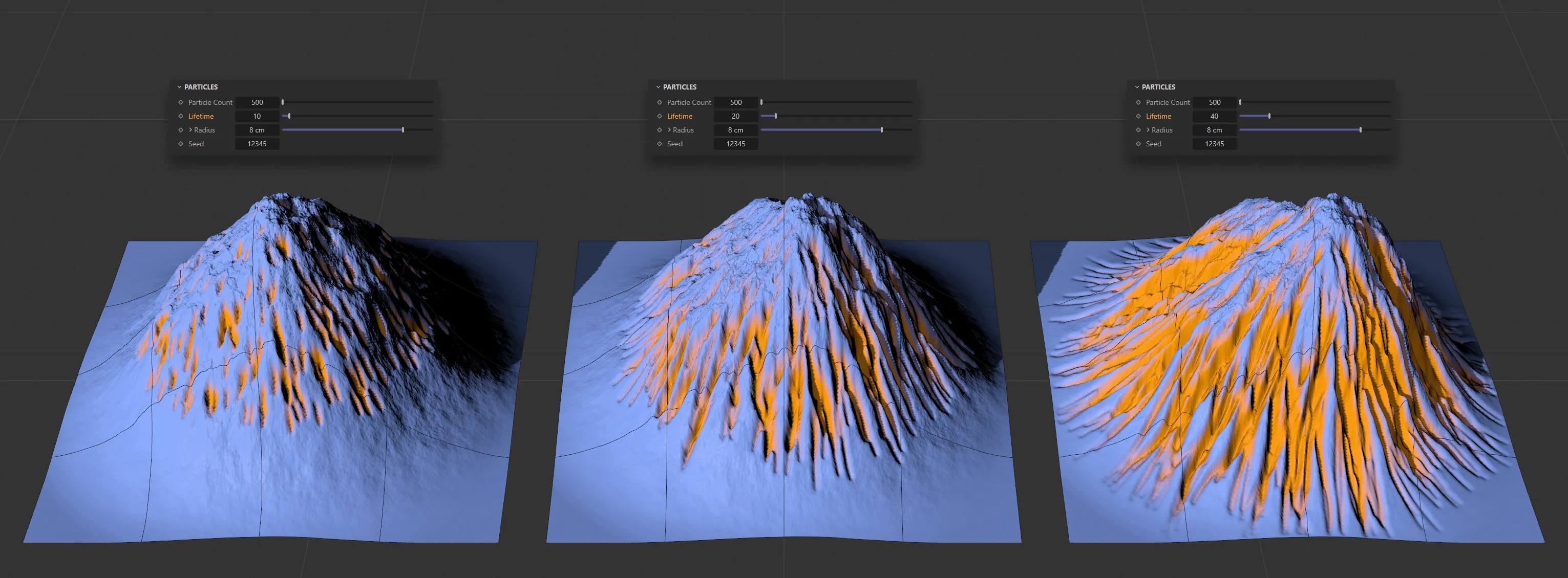
In this image, with a Particle Count of 500, the Lifetime, in frames, is 10, then 20, then 40, from left to right.
Radius
Section titled “Radius”This slider allows you to determine the radius of the particles.
Set at 3cm, by default, you can increase this to see an impact on the troughs caused by the erosion as the sediment is displaced downhill.
Clicking on the drop-down arrow reveals a Radius Life curve.
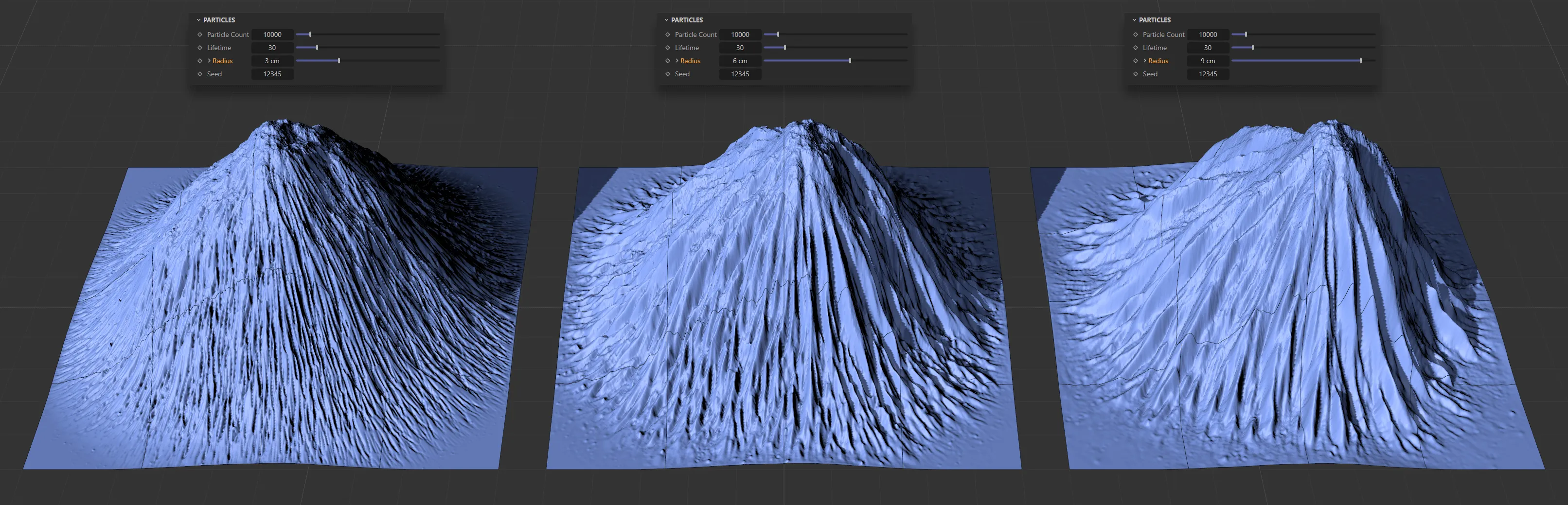
Here, with an identical Particle Count (10000) and Lifetime (30 frames), the particles’ Radius setting, from left to right, is 3cm, 6cm and 9cm, respectively.
Radius Life
Section titled “Radius Life”This enables you to adjust the radius of the particles over their life.
The X-axis represents the lifetime of the particles and the Y-axis is the radius.
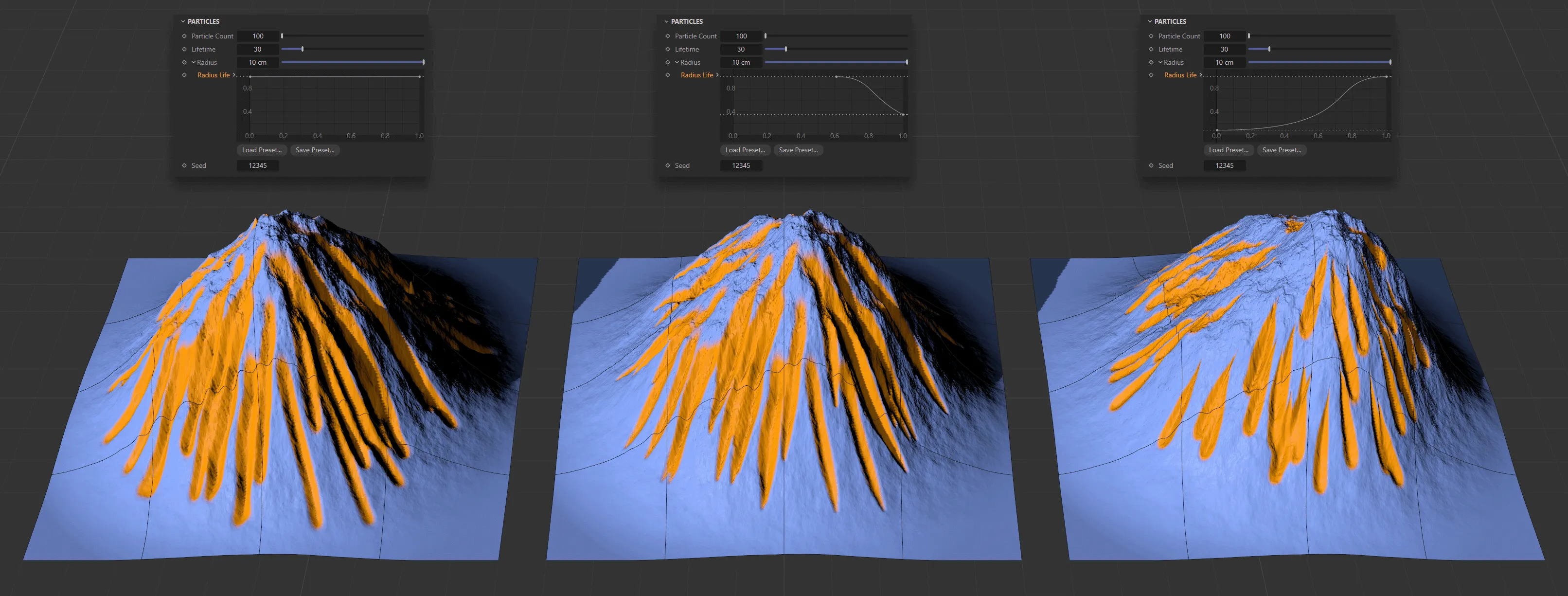
The Radius Life spline curve settings above are driving the terrain creations, with all other settings identical.
Change the Seed value to get a different random look, based on your settings, with particles being born in different positions.
Erosion
Section titled “Erosion”These settings are simulation settings and are very inter-dependent, which means that an alteration to one will have an effect on others.
Capacity
Section titled “Capacity”Represents how much of the eroded material each particle can carry with it.
Once it reaches this Capacity setting, it will begin depositing material.
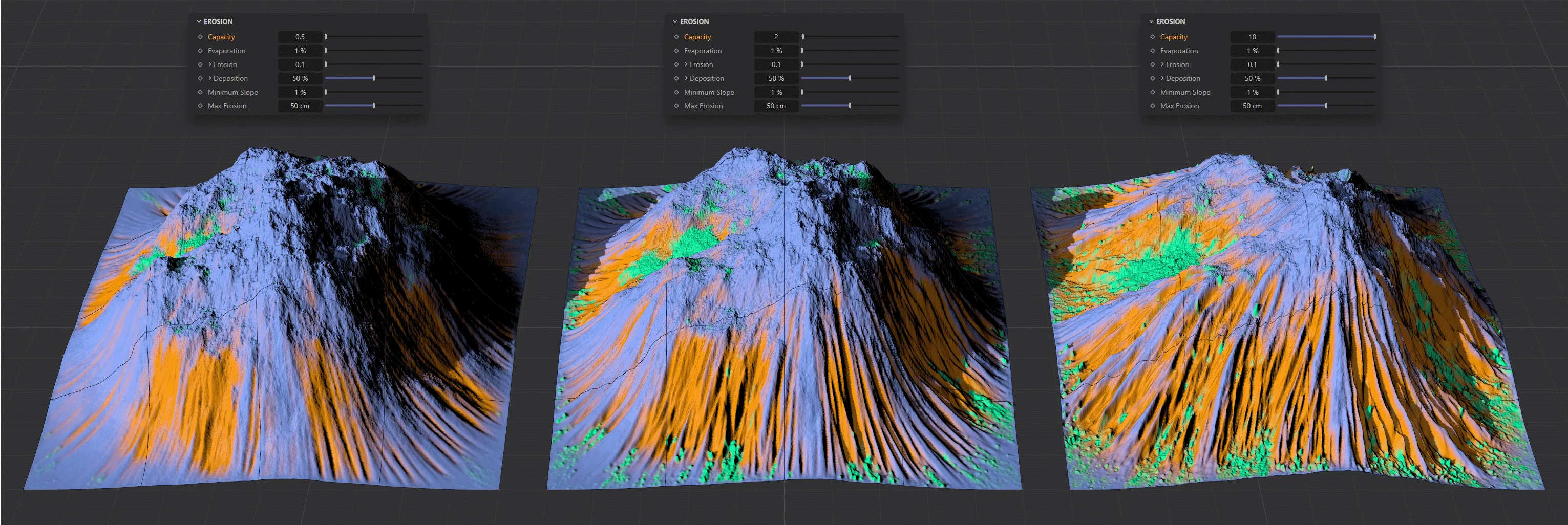
In this image, you can see three Capacity settings, with 0.5, on the left, rising to 2 in the center and then 10, on the right.
Evaporation
Section titled “Evaporation”The rate at which the particles will evaporate over their lifetime.
The default setting of 1% will work in most instances.
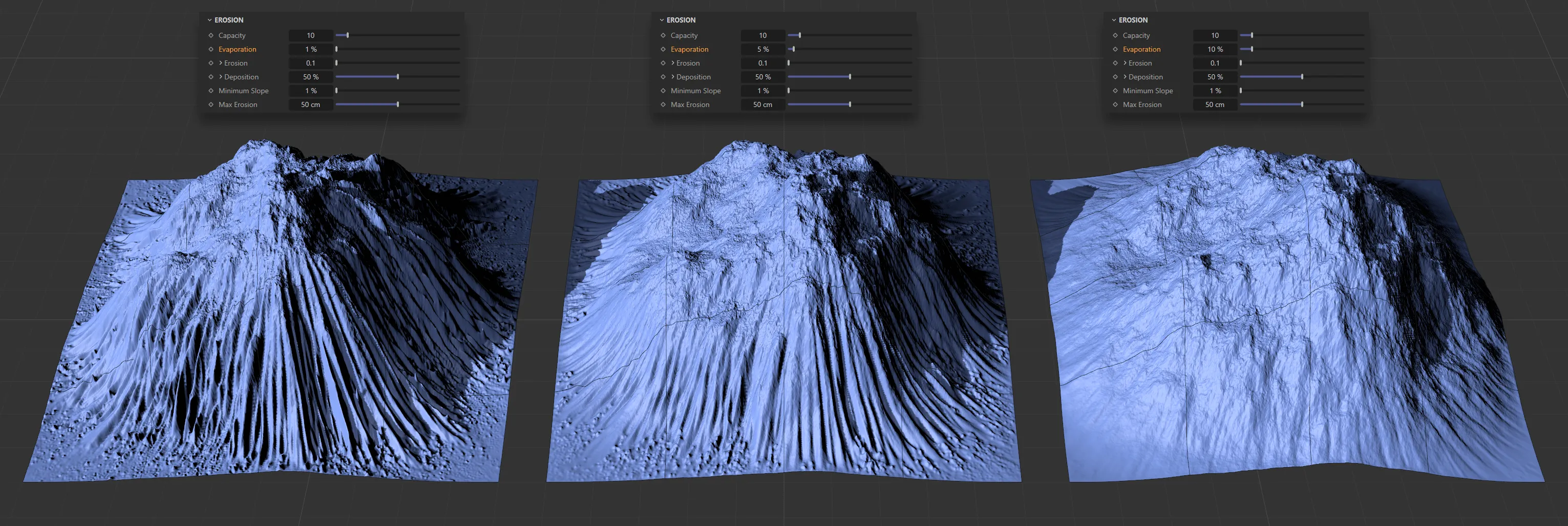
The only change in these three landscapes is the Evaporation setting: 1%, increased to 5% and, finally, 10%, from left to right.
Erosion
Section titled “Erosion”This value represents the amount of terrain that each particle can erode in a frame.
The drop-down arrow will reveal further settings: Erode Profile and Erode Life.
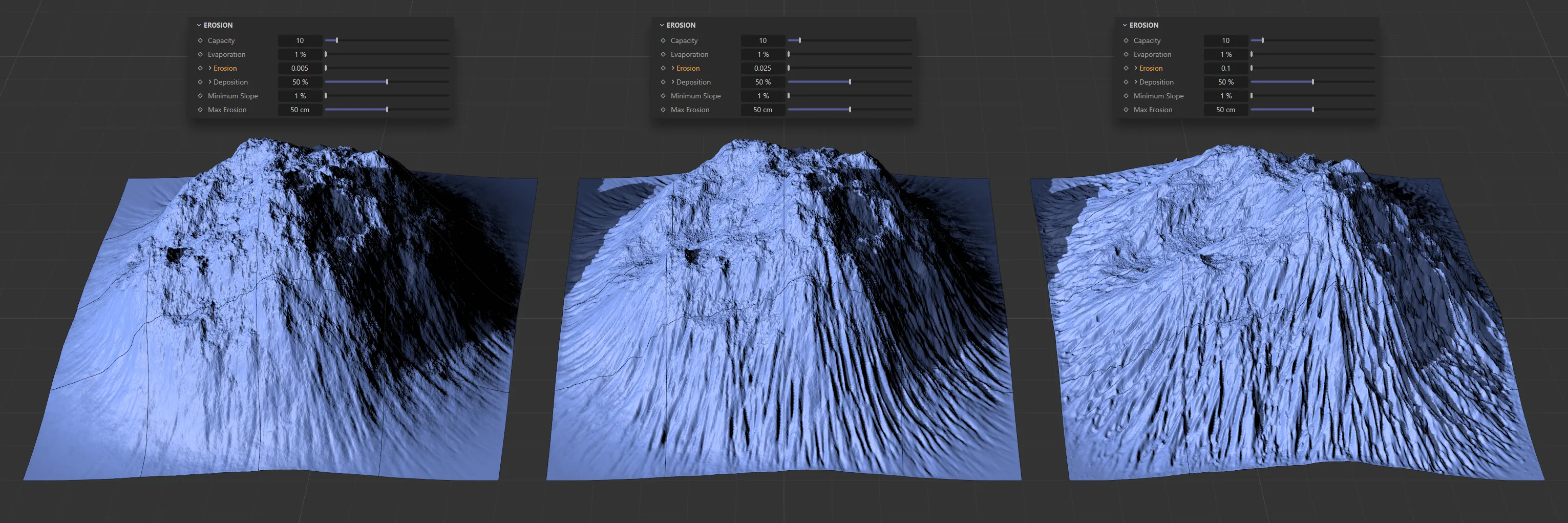
The Erosion value is increasing in this image, from the left, 0.005, to 0.025, then 0.1 on the right.
Erode Profile
Section titled “Erode Profile”This curve represents the shape of the trough caused by the Erosion setting.
The default setting is a smooth curve, which will normally be satisfactory, but can be altered if you are seeking a different look.
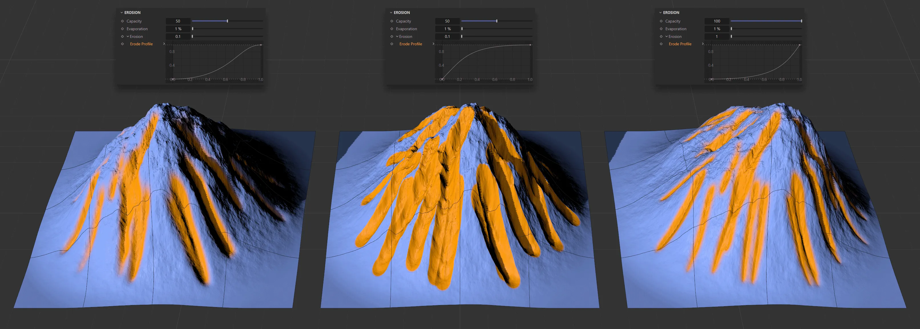
Three different erosion patterns on terrains, driven by the Erode Profile curve settings above.
Erode Life
Section titled “Erode Life”The X-axis represents the lifetime of each particle and the Y-axis is the amount of erosion, up to the Erosion level setting.
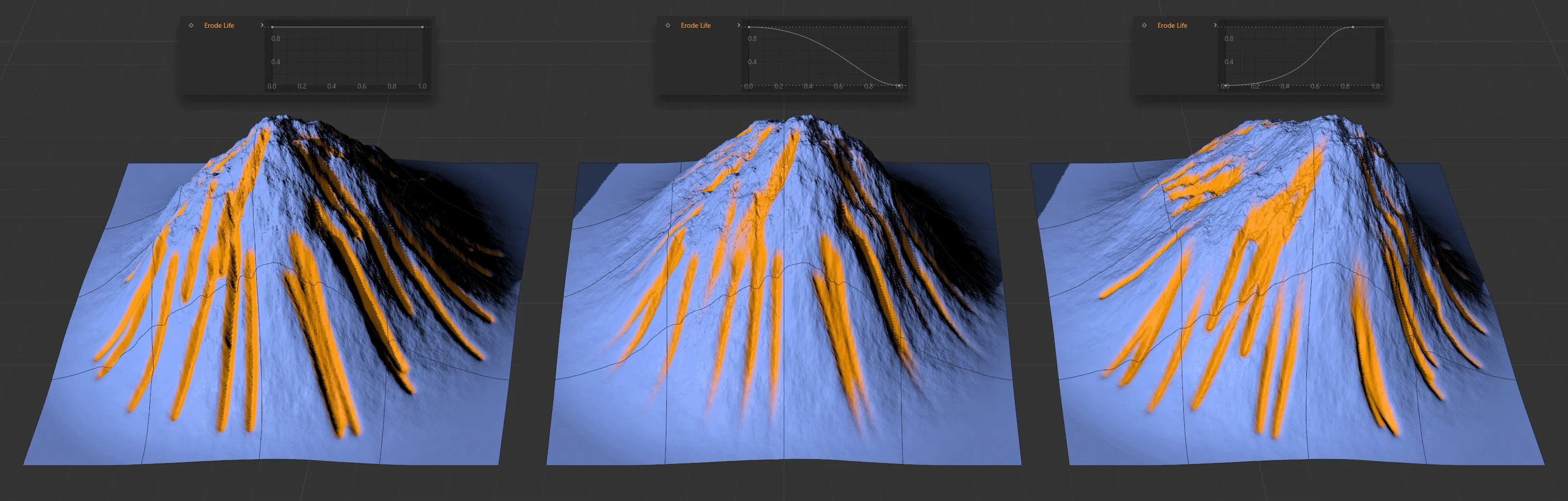
Here, the lifetime of the particles is manipulated on the Erode Life curves, to give three different levels of erosion.
Load Preset
Section titled “Load Preset”Both of these curves have presets, which can be loaded in.
Save Preset
Section titled “Save Preset”It is possible to save any customized curves, for your future use.
Deposition
Section titled “Deposition”The percentage amount that each particle deposits, based on the capacity that it is carrying.
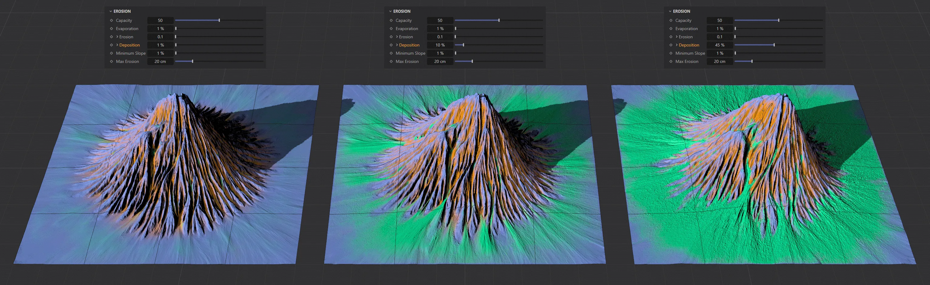
Deposition levels of 1%, on the left, 10% in the center, rising up to 45% on the right.
Deposit Profile
Section titled “Deposit Profile”Customize the amount and placement of deposition with the spline curve.
Minimum Slope
Section titled “Minimum Slope”This is used in the Capacity and Deposition calculations, to mitigate the deposits on the terrain.
Increasing this value will decrease the amount of deposition on flatter areas but will need quite high levels to see an impact in certain settings.
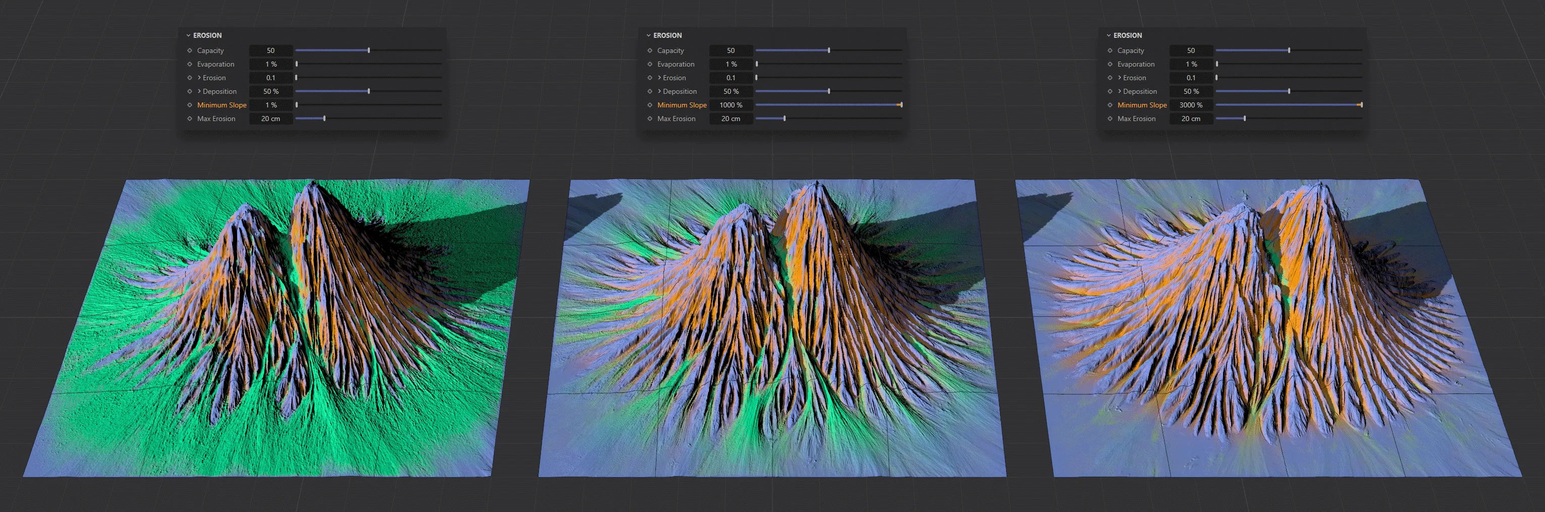
This image shows the contrast between Minimum Slope values of 1% on the left, 1000% in the middle image and 3000% on the right.
Max Erosion
Section titled “Max Erosion”By default, this is set at 50cm; it is the maximum that any particle can erode.
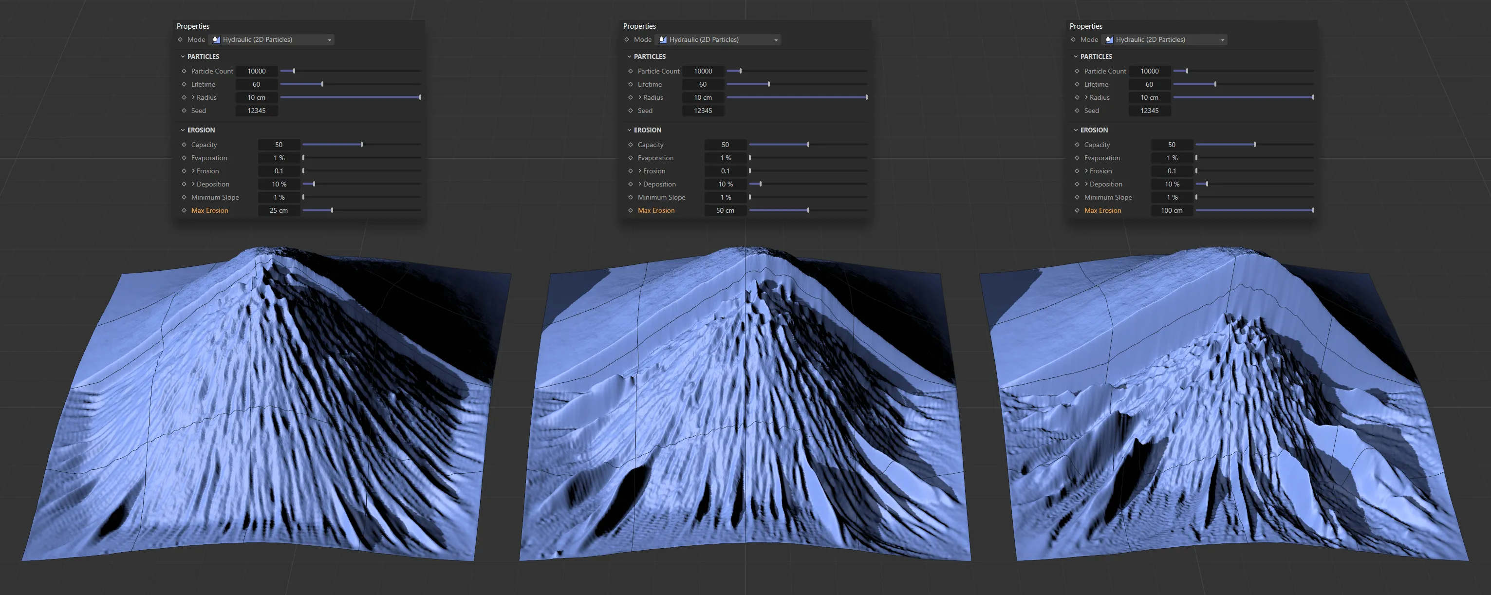
This image is being masked with a linear gradient, affecting half the terrain’s surface. It demonstrates how the Max Erosion setting acts as a hard limit, even with identical erosion settings. The terrain can only be displaced in the Y-axis (vertically) by the amount in the Max Erosion setting.
Output Erosion Maps
Section titled “Output Erosion Maps”This check-box will create a vertex map, based on the erosion and another one based on the deposition.
Clicking the check-box will result in two vertex map tags appearing in the Object Manager, next to the tfTerrain object.
Filter
Section titled “Filter”Set to Everywhere, by default, this determines where you want the rain to fall, causing the erosion.
You can change this to: Below or Above.
Everywhere
Section titled “Everywhere”Erosion will be evident throughout the terrain, as rain will fall everywhere.
Opens up a Height parameter, where you can set a limit, below which rain will fall, but not above that level.
Sets the height limit, above which rain will fall.
Height
Section titled “Height”Input a value to work in conjunction with the Below or Above settings.
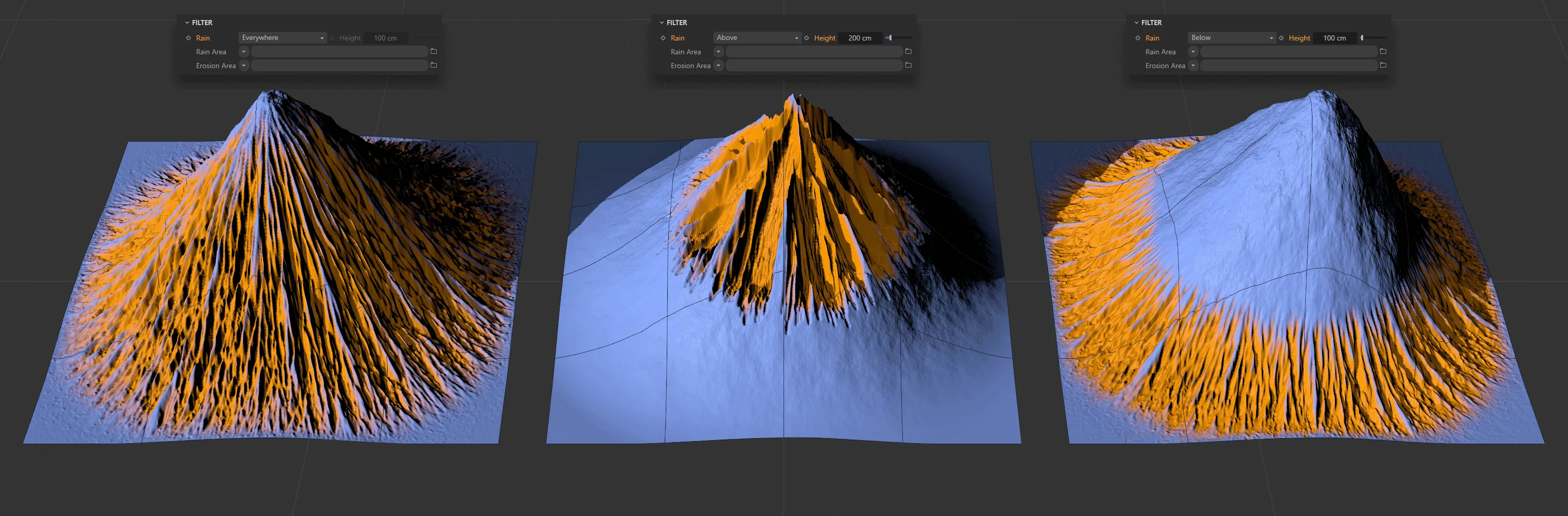
In this image there are three different Rain settings. On the left, Rain is set to Everywhere. In the center, Rain is set to Above a Height value of 200cm. Finally, on the right, the Rain is set to Below a Height setting of 100cm.
Rain Area
Section titled “Rain Area”You can use shaders to determine where the rain will fall.
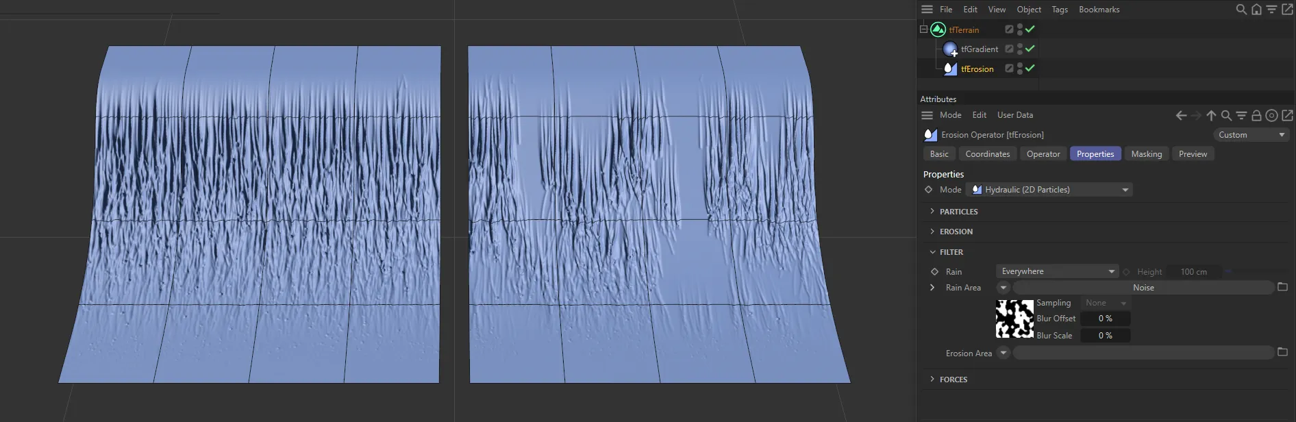
The Noise shader is driving the Rain Area setting on the right-hand terrain.
Erosion Area
Section titled “Erosion Area”You can use shaders to determine where the landscape will erode.
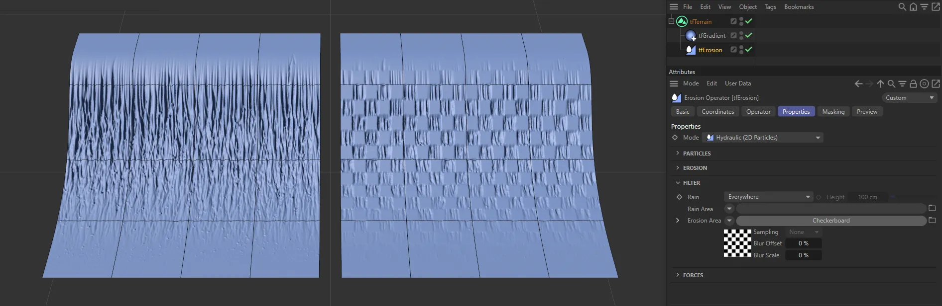
Here, a black and white Checkerboard shader has been used to determine the Erosion Area.
Forces
Section titled “Forces”Gravitation
Section titled “Gravitation”This controls the downward force on the particles.
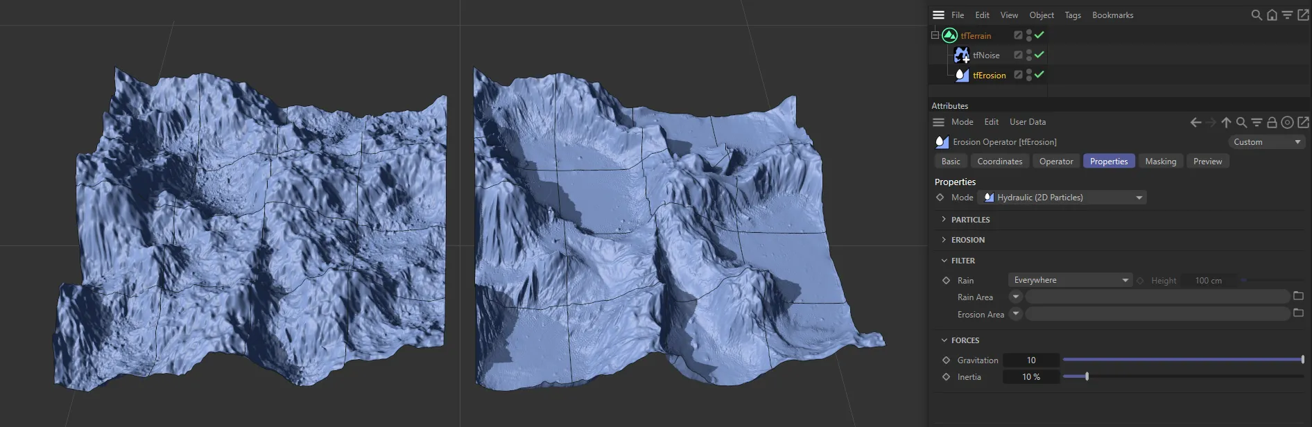
This image shows the contrast between Gravitation values of 1 and 10.
Inertia
Section titled “Inertia”This is the inertia force of the individual particle.
With a low setting, it is easier to change the direction of the particles as they travel downward.
At a higher setting, there will be far more channels, as more particles refuse to change direction.
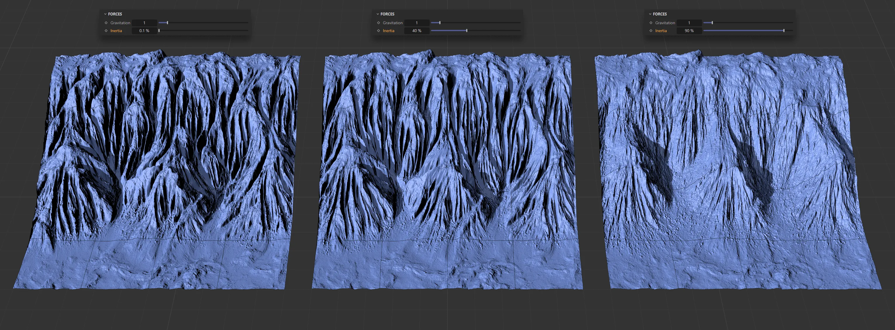
With Inertia set at 0.1%, 40% and 90%, from left to right, respectively.
Hydraulic (X-Particles) mode
Section titled “Hydraulic (X-Particles) mode”The majority of the Properties tab settings are identical to those of the 2D mode, above.
The additional settings are explained below.
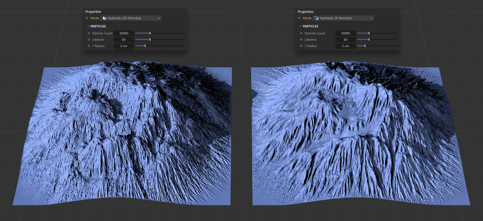
The image on the left shows the effect of tfErosionHydraulic, with a Mode setting of Hydraulic (2D Particles), against the Mode setting of Hydraulic (X-Particles), on the right.
Particles
Section titled “Particles”Liquid
Section titled “Liquid”Introduces a fluid solver into the simulation, resulting in the particles interacting with each other in a fluid-like way.
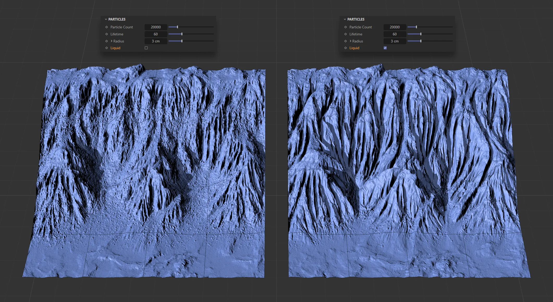
Above, the Particle Count is 20000, with a Lifetime setting of 60 and Radius set at 3cm. Liquid is enabled on the right-hand terrain.
Distance to Terrain
Section titled “Distance to Terrain”This value sets the distance, from the particle, within which erosion will take place.
Clicking the drop-down arrow will open up a Distance Falloff curve.
Distance Falloff
Section titled “Distance Falloff”The X-axis represents the distance from the particle to the Distance to Terrain setting and the Y-axis is the falloff.
Iterations
Section titled “Iterations”Each iteration is a simulation run on the terrain and will erode the terrain a little more, creating deeper particle channels the more times it is run.
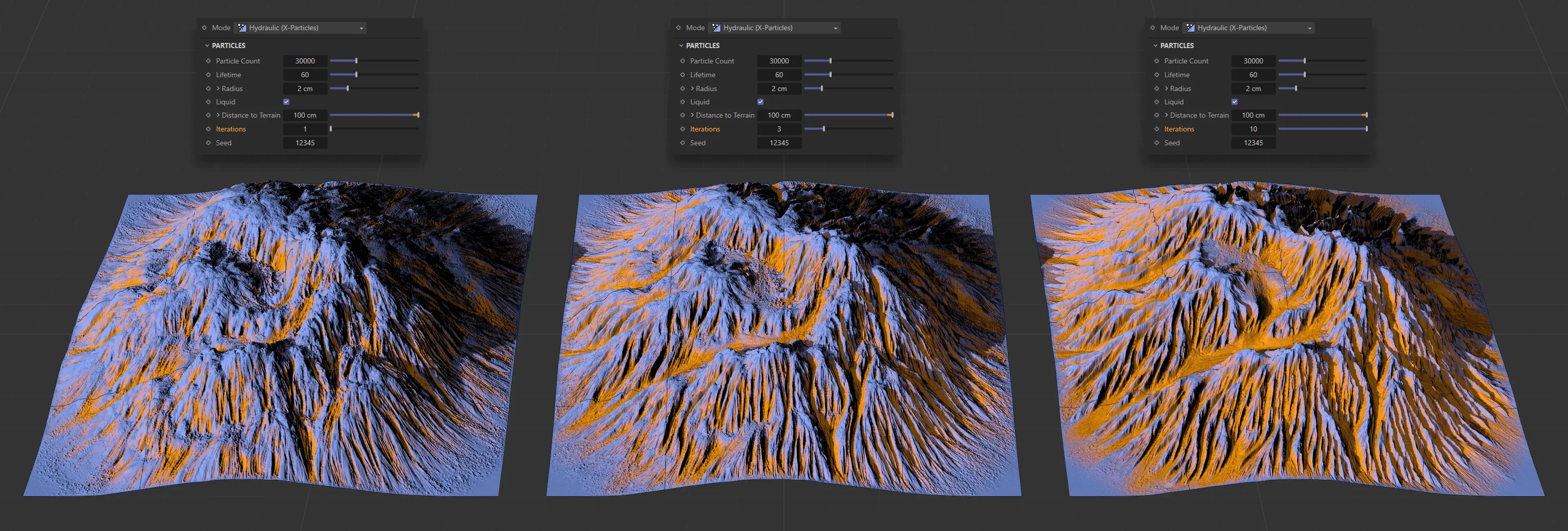
Iterations set at 1 on the left, raised to 3 in the center and 10 on the right.
Forces
Section titled “Forces”Friction
Section titled “Friction”With 3D geometry, it is possible to simulate the friction force from the particles moving downhill.
This can be increased to see more erosion on the terrain.
Modifiers
Section titled “Modifiers”Here it is possible to bring in X-Particles modifiers to art-direct how the particles move across the terrain, simulating forces such as wind and turbulence.
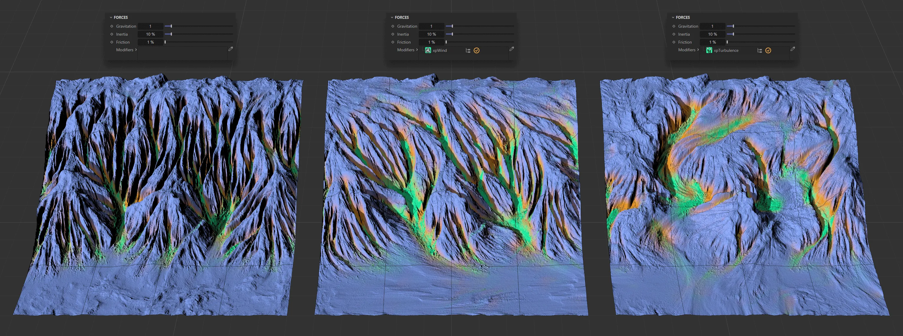
The left-hand terrain has no modifier. In the center, xpWind is active and, on the right, xpTurbulence has been activated, with erosion clearly visible following the direction of the modifiers.
Copyright © 2026 INSYDIUM LTD. All rights reserved.