nxLimit
nxLimit constrains particle properties to defined ranges.
nxLimit uses a layer-based system, allowing multiple limit operations to be stacked and blended together.
Object Properties
Section titled “Object Properties”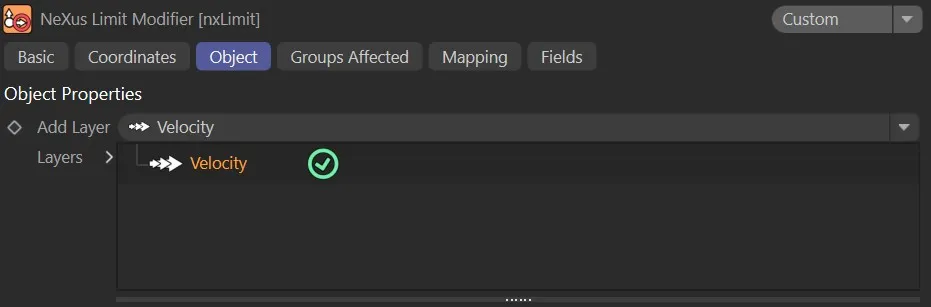
nxLimit Object tab.
Add Layer
Section titled “Add Layer”Adds a new limit layer to the stack.
Each layer can be set to a different operation mode and blended with the layers below it.
Layers
Section titled “Layers”The layer stack.
Layers can be enabled or disabled using the toggle on the left of each entry.
Layers are processed from bottom to top.
Layer Settings
Section titled “Layer Settings”When a layer is selected in the Layers tree, its settings are shown below.
Each layer has a General tab and a Falloff tab.
General tab
Section titled “General tab”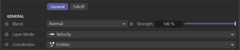
Layer Mode
Section titled “Layer Mode”Sets the operation for this layer.
The available modes are Velocity, Position, Scale, Rotation, Speed, Radius, Mass and User Value.
Sets how this layer is blended with the result of the layers below it.
The available blend modes are Normal, Add, Subtract, Multiply, Difference, Screen, Overlay, Min and Max.
Strength
Section titled “Strength”The blend strength of this layer.
Falloff tab
Section titled “Falloff tab”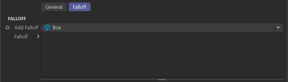
Add Falloff
Section titled “Add Falloff”Adds a falloff to this layer.
The available falloff types are Box, Linear, Sphere and Noise.
Falloff
Section titled “Falloff”The falloff stack for this layer.
Multiple falloffs can be added and combined.
Velocity operation settings
Section titled “Velocity operation settings”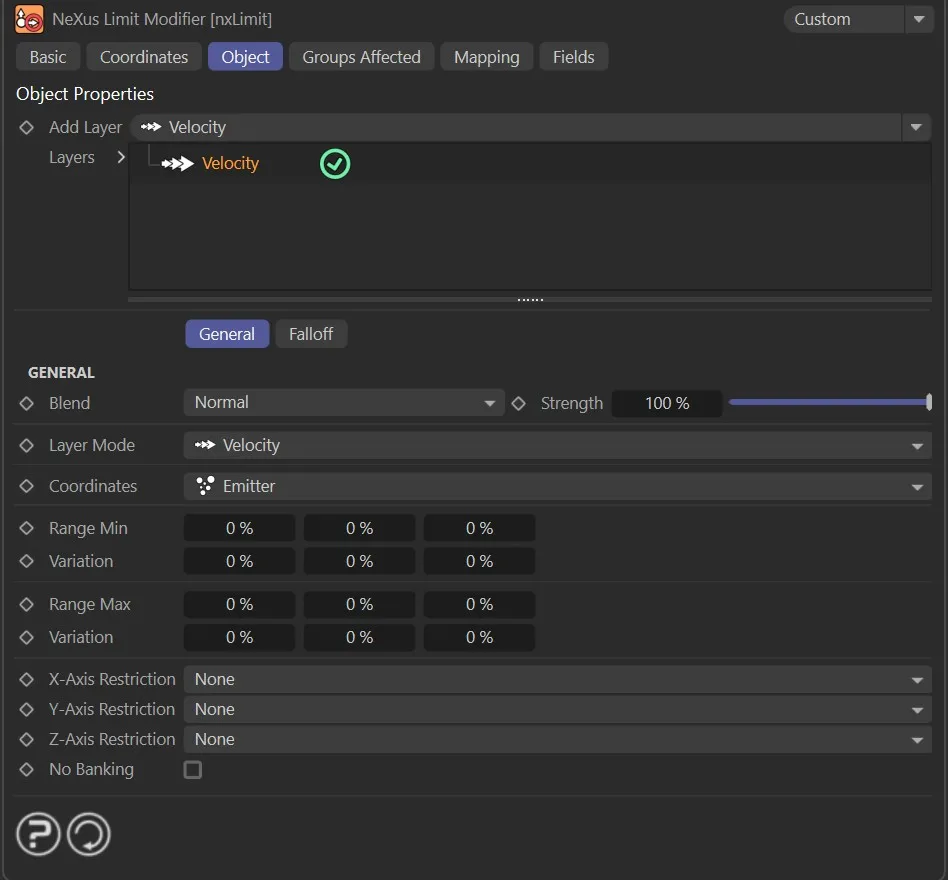
Velocity limits the direction of particle movement along each axis.
Coordinates
Section titled “Coordinates”Sets the coordinate space used to evaluate the velocity limits.
Set as Emitter, by default.
The alternatives are World and Custom.
An object whose coordinate space is used when Coordinates is set to Custom.
Range Min
Section titled “Range Min”The minimum velocity along each axis, as a percentage of the full velocity range.
Variation
Section titled “Variation”Adds a random variation to the Range Min value on each axis.
Range Max
Section titled “Range Max”The maximum velocity along each axis, as a percentage of the full velocity range.
Variation
Section titled “Variation”Adds a random variation to the Range Max value on each axis.
X-Axis Restriction
Section titled “X-Axis Restriction”Restricts the velocity component on the X axis.
Set as None, by default.
X+ allows only positive velocity on the X axis.
X- allows only negative velocity on the X axis.
Y-Axis Restriction
Section titled “Y-Axis Restriction”Restricts the velocity component on the Y axis.
Set as None, by default.
Y+ allows only positive velocity on the Y axis.
Y- allows only negative velocity on the Y axis.
Z-Axis Restriction
Section titled “Z-Axis Restriction”Restricts the velocity component on the Z axis.
Set as None, by default.
Z+ allows only positive velocity on the Z axis.
Z- allows only negative velocity on the Z axis.
No Banking
Section titled “No Banking”If enabled, particles will not bank or tilt as they move along a curved path.
Position operation settings
Section titled “Position operation settings”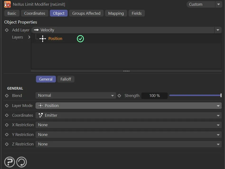
Position constrains particles to a defined region along each axis.
Coordinates
Section titled “Coordinates”Sets the coordinate space used to evaluate the position limits.
Set as Emitter, by default.
The alternatives are World, Custom and Particle.
An object whose coordinate space is used when Coordinates is set to Custom.
X Restriction
Section titled “X Restriction”Sets the restriction mode for the X axis.
Set as None, by default.
The alternatives are X+, X-, Range and Fixed.
X+ clamps the particle position to be at or above the X Min value.
X- clamps the particle position to be at or below the X Max value.
Range clamps the particle position between X Min and X Max.
Fixed locks the particle position to the X Fixed value.
X Min, Variation
Section titled “X Min, Variation”The minimum position on the X axis.
Available when X Restriction is set to X+ or Range.
X Max, Variation
Section titled “X Max, Variation”The maximum position on the X axis.
Available when X Restriction is set to X- or Range.
X Fixed
Section titled “X Fixed”The fixed position on the X axis.
Available when X Restriction is set to Fixed.
Y Restriction
Section titled “Y Restriction”Sets the restriction mode for the Y axis.
The options and behaviour are the same as X Restriction.
Z Restriction
Section titled “Z Restriction”Sets the restriction mode for the Z axis.
The options and behaviour are the same as X Restriction.
Scale operation settings
Section titled “Scale operation settings”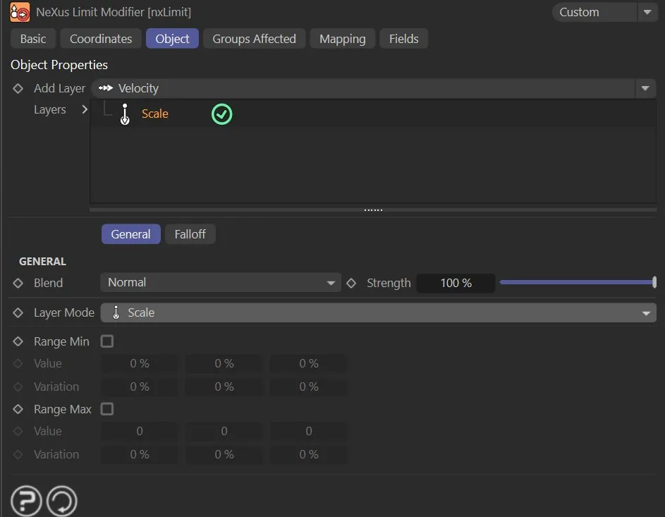
Scale constrains the size of particles to a minimum and maximum range.
Range Min
Section titled “Range Min”If enabled, a minimum scale limit is applied.
The minimum scale limit on each axis.
Variation
Section titled “Variation”Adds a random variation to the minimum Value on each axis.
Range Max
Section titled “Range Max”If enabled, a maximum scale limit is applied.
The maximum scale limit on each axis.
Variation
Section titled “Variation”Adds a random variation to the maximum Value on each axis.
Rotation operation settings
Section titled “Rotation operation settings”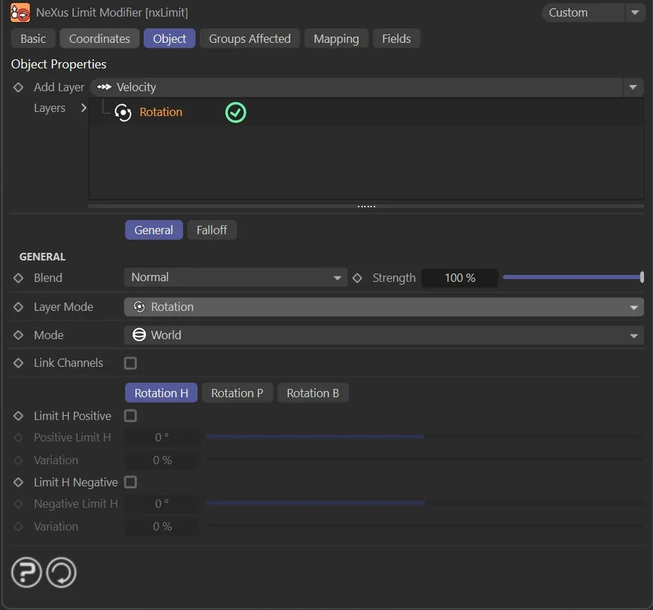
Rotation constrains particle rotation within defined positive and negative limits on each axis.
Set as World, by default.
The alternative is Relative.
In World mode, the rotation limits are applied in world space.
In Relative mode, the rotation limits are applied relative to the particle’s own axes.
Link Channels
Section titled “Link Channels”If enabled, all rotation axes share the same positive and negative limits.
When disabled, each axis is controlled independently using the Rotation H, Rotation P and Rotation B tabs.
Rotation H, Rotation P, Rotation B tabs
Section titled “Rotation H, Rotation P, Rotation B tabs”Each tab controls the limits for the heading (H), pitch (P) and bank (B) rotation axes.
The controls below apply to each tab.
Limit H Positive
Section titled “Limit H Positive”If enabled, a positive rotation limit is applied to the heading axis.
Positive Limit H
Section titled “Positive Limit H”The maximum positive rotation on the heading axis, in degrees.
Variation
Section titled “Variation”Adds a random variation to the positive limit.
Limit H Negative
Section titled “Limit H Negative”If enabled, a negative rotation limit is applied to the heading axis.
Negative Limit H
Section titled “Negative Limit H”The maximum negative rotation on the heading axis, in degrees.
Variation
Section titled “Variation”Adds a random variation to the negative limit.
Link Channels mode
Section titled “Link Channels mode”When Link Channels is enabled, the per-axis tabs are replaced by the following controls.
Limit All Positive
Section titled “Limit All Positive”If enabled, a positive rotation limit is applied to all axes simultaneously.
Positive Limit All
Section titled “Positive Limit All”The maximum positive rotation on all axes, in degrees.
Variation
Section titled “Variation”Adds a random variation to the positive limit.
Limit All Negative
Section titled “Limit All Negative”If enabled, a negative rotation limit is applied to all axes simultaneously.
Negative Limit All
Section titled “Negative Limit All”The maximum negative rotation on all axes, in degrees.
Variation
Section titled “Variation”Adds a random variation to the negative limit.
Speed operation settings
Section titled “Speed operation settings”
Speed constrains the overall movement speed of particles.
Range Min
Section titled “Range Min”If enabled, a minimum speed limit is applied.
The minimum speed limit.
Variation
Section titled “Variation”Adds a random variation to the minimum Value.
Range Max
Section titled “Range Max”If enabled, a maximum speed limit is applied.
The maximum speed limit.
Variation
Section titled “Variation”Adds a random variation to the maximum Value.
Radius operation settings
Section titled “Radius operation settings”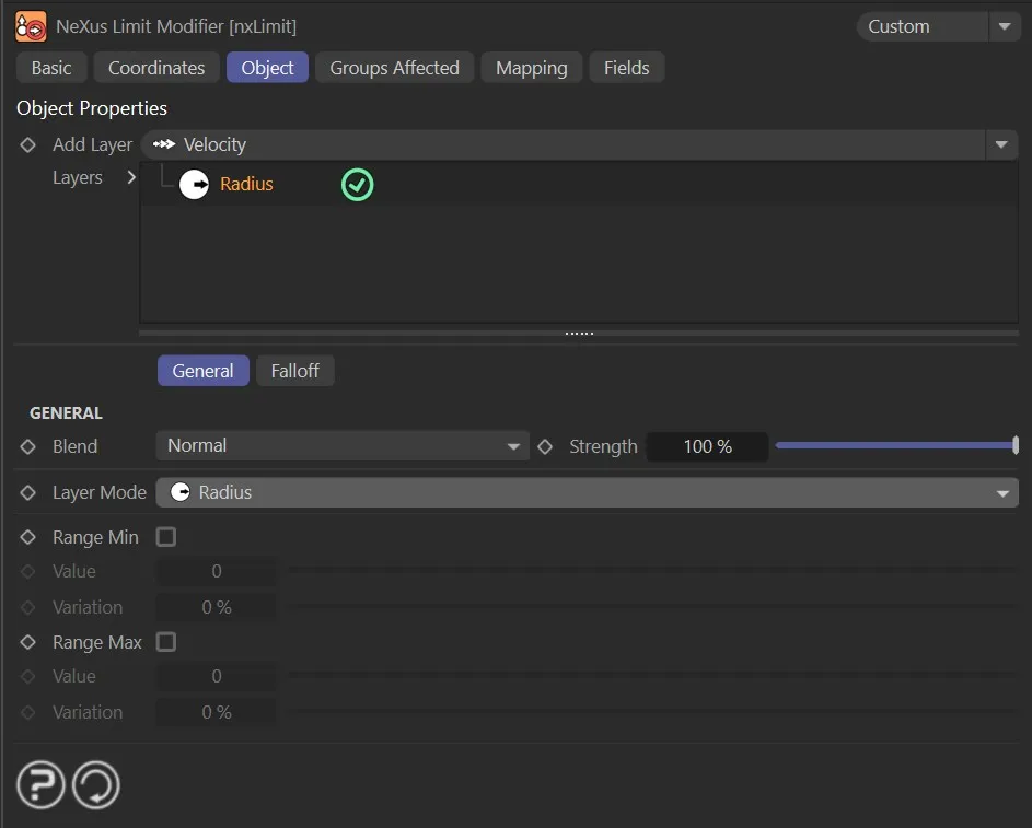
Radius constrains the radius of particles.
The controls are the same as the Speed operation settings.
Mass operation settings
Section titled “Mass operation settings”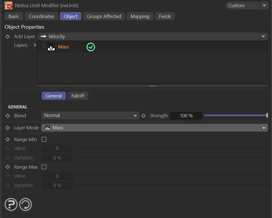
Mass constrains the mass of particles.
The controls are the same as the Speed operation settings.
User Value operation settings
Section titled “User Value operation settings”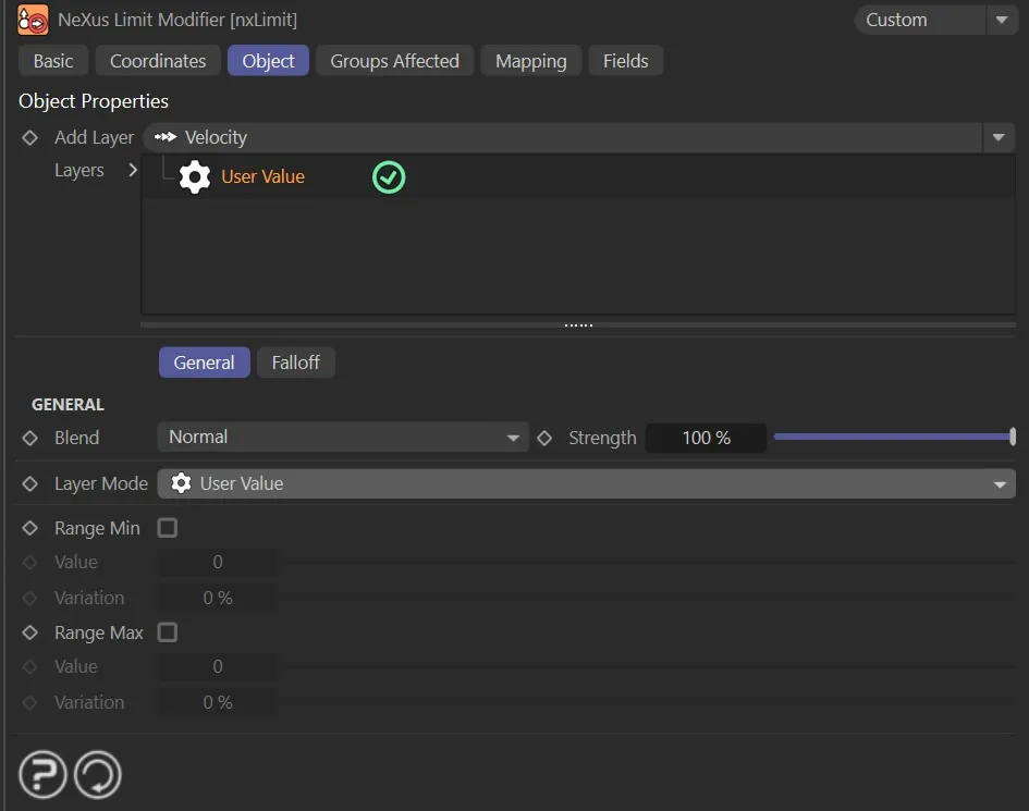
User Value constrains a custom user-defined particle data channel.
The controls are the same as the Speed operation settings.
Groups Affected tab
Section titled “Groups Affected tab”Groups
Section titled “Groups”To specify the group, drag and drop the desired Group object into this field.
This setting is useful if you want to ensure that the spawned particles are, or are not, affected by nxLimit.
Mapping tab
Section titled “Mapping tab”The modifier’s settings can be mapped to particle data.
Use the dedicated manual page, below, for instructions on how this works.
Fields tab
Section titled “Fields tab”You can use the Fields options to control where nxLimit operates.
Copyright © 2026 INSYDIUM LTD. All Rights Reserved.