nxDirection
Overview Video
Section titled “Overview Video”nxDirection changes the direction of particles passing through it.
nxDirection uses a layer-based system, allowing multiple direction effects to be stacked and blended together. Each layer has its own operation, blend mode, and falloff.
Object Properties
Section titled “Object Properties”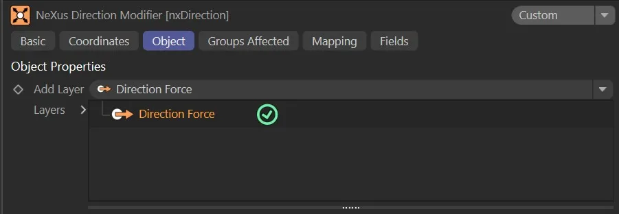
nxDirection Object tab.
Visible in Editor
Section titled “Visible in Editor”Enabled by default, the direction for the particles is shown by an arrow in the viewport.
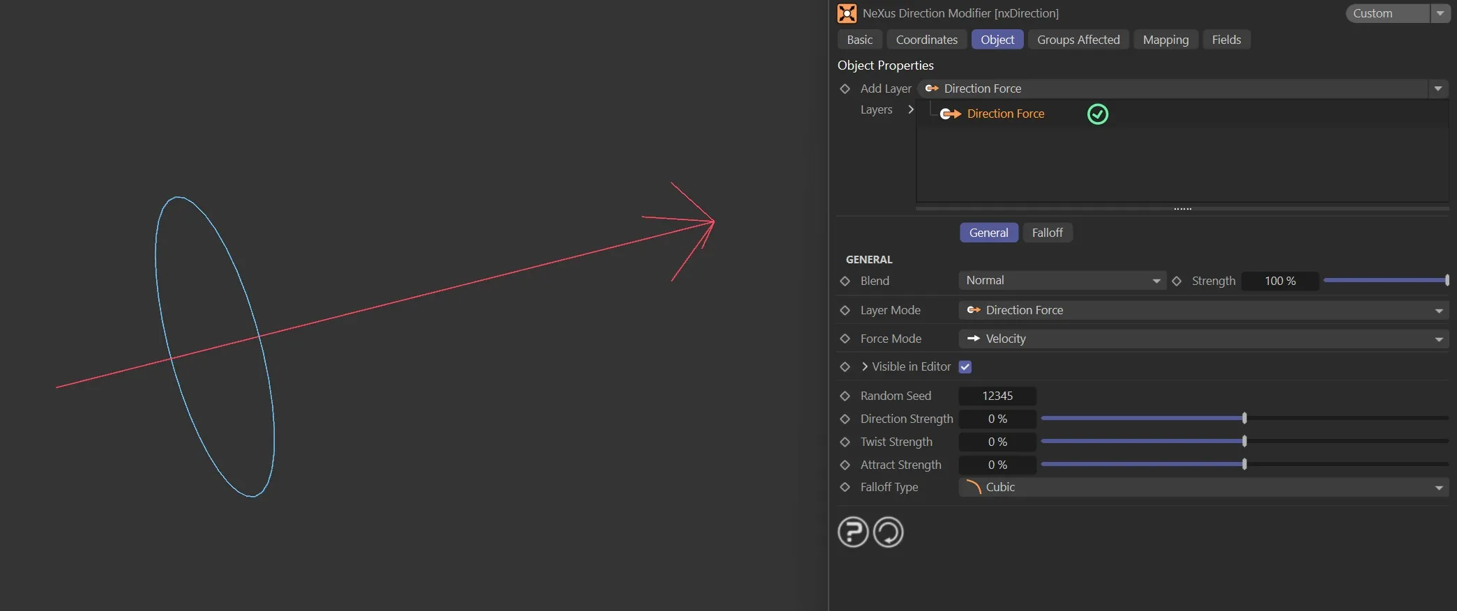
nxDirection arrow when Visible in Editor is enabled.
Add Layer
Section titled “Add Layer”Adds a new direction layer to the stack.
Each layer can be set to a different operation and blended with the layers below it.
Layers
Section titled “Layers”The layer stack.
Layers can be enabled or disabled using the toggle on the left of each entry.
Layers are processed from bottom to top.
Layer Settings
Section titled “Layer Settings”When a layer is selected in the Layers tree, its settings are shown below.
Each layer has a General tab and a Falloff tab.
General tab
Section titled “General tab”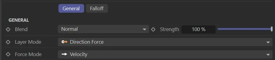
Operation
Section titled “Operation”Set as Direction Force, by default.
The other options are: Use Modifier Rotation, Relative, Absolute, Circular and Ring.
Sets how this layer is blended with the result of the layers below it.
The available blend modes are Normal, Add, Subtract, Multiply, Difference, Screen, Overlay, Min and Max.
Strength
Section titled “Strength”The blend strength of this layer.
Falloff tab
Section titled “Falloff tab”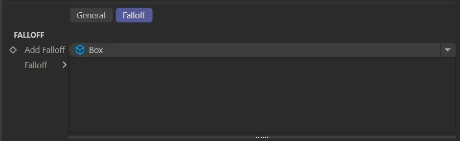
Each direction layer has a Falloff tab to restrict where the layer’s effect applies in space.
Add Falloff
Section titled “Add Falloff”Adds a falloff to this layer.
A quick-select button allows choosing a built-in falloff shape (Box, Linear, Sphere, or Noise) directly on the layer, without needing a separate nxFalloff object.
For more complex or reusable falloffs, an nxFalloff object can be dragged from the scene into the layer’s falloff tree.
Falloff
Section titled “Falloff”The falloff stack for this layer.
Multiple falloffs can be added and combined.
Direction Force operation settings
Section titled “Direction Force operation settings”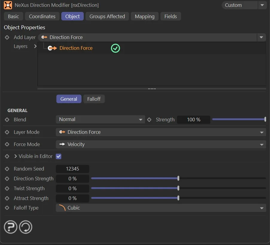
Direction Force is the default operation. It combines three independent forces, giving more sculpted control over particle movement than a simple direction vector.
Direction Strength
Section titled “Direction Strength”Pushes particles along the object’s local forward axis (−100% to 100%).
Positive values push along the axis; negative values push against it.
Twist Strength
Section titled “Twist Strength”Makes particles spiral around the direction axis (−100% to 100%).
Positive and negative values spiral in opposite directions.
Attract Strength
Section titled “Attract Strength”Pulls particles toward or pushes them away from the object’s centre (−100% to 100%).
Positive values attract; negative values repel.
Falloff Type
Section titled “Falloff Type”A built-in distance-based falloff for the force.
Set as Flat, by default.
The other options are: Linear, Quadratic and Cubic.
- Flat: constant force regardless of distance
- Linear: force decreases linearly with distance
- Quadratic: force decreases with the square of distance
- Cubic: force decreases with the cube of distance
Force Mode
Section titled “Force Mode”Controls whether the force is applied as a direct velocity change or as an acceleration-based force.
Set as Velocity, by default.
The alternative is Acceleration.
- Velocity: applies the force as a direct change to particle velocity
- Acceleration: applies force as an acceleration that interacts with particle mass
Use Modifier Rotation operation settings
Section titled “Use Modifier Rotation operation settings”With this mode, the direction that the particles will take is the direction in which the modifier is pointing.
This lets you simply rotate the modifier to point in the desired direction, without having to enter a heading and pitch value.
Animation with Operation set as Use Modifier Rotation. Here the particle direction is set globally, based on the modifier rotation.
Relative operation settings
Section titled “Relative operation settings”The new direction set by the Heading and Pitch parameters will be relative to the particles’ current direction, rather than an absolute direction.
This is a continual calculation every frame, resulting in a constant change in direction.
In this animation, Operation is set as Relative, changing each particle’s direction relative to its current orientation.
Absolute operation settings
Section titled “Absolute operation settings”The Absolute setting will cause the particles to move in the direction set by the Heading and/or Pitch sliders.
Animation to show Operation set as Absolute, globally setting the particle direction based on the Heading and Pitch values.
Circular operation settings
Section titled “Circular operation settings”This mode is dependent on the particle emitter orientation, which should be in the Y+ axis.
With each frame, the modifier will alter the particles’ direction relative to their current direction, dependent on the Heading and Acuteness of Turn settings.
The end result is that the particles will move in a circle, but the time it takes to do this is determined by the settings mentioned.
Animation showing Operation set as Circular, adding relative direction and upwards motion using the Y-Axis Kick feature.
Ring operation settings
Section titled “Ring operation settings”In this mode, you can make the particles adopt a flat ring or disc shape.
The particles will deviate from their original path by a maximum value set in the Angle Limit parameter.
The speed with which they deviate is controlled by the Step Per Frame parameter.
The Angle Limit can be set beyond 90°. When it reaches 360°, the Loop parameter becomes available, enabling particles to loop continuously along their ring path.
The final Operation setting of Ring is shown in this animation, directing particles into a cone shaped motion.
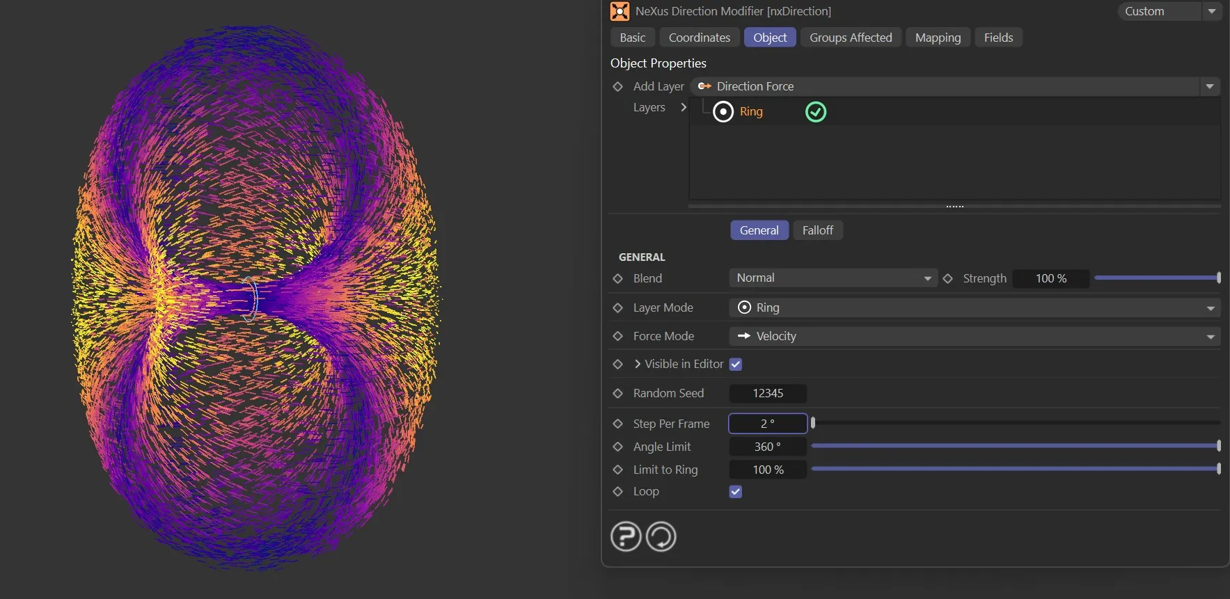
Ring mode with Angle Limit at 360° and Loop enabled.
Shared parameters
Section titled “Shared parameters”The following parameters apply to one or more of the older operation modes (Use Modifier Rotation, Relative, Absolute, Circular, Ring). They are not used by the Direction Force operation.
Random Seed
Section titled “Random Seed”Gives a different random look if angle variation is being used for the Heading, Pitch and Y-Axis Kick settings.
Heading
Section titled “Heading”This is the particle heading (the ‘H’ in an object’s rotation), where you can change the heading direction that the particles are traveling.
Animation demonstrating the effect of the Heading slider, changing particle direction.
Variation +/-
Section titled “Variation +/-”This parameter allows you to add some random variation to the Heading setting.
Animation illustrating manipulation of the Variation value, adding random circular motion.
This is the particle pitch (the ‘P’ in an object’s rotation), where you can change the pitch direction that the particles are traveling.
Variation +/-
Section titled “Variation +/-”This parameter allows you to add some random variation to the heading produced.
Use Strength
Section titled “Use Strength”Enabled by default, activating the Strength multiplier setting.
If deactivated, particles are born heading in the direction of the nxDirection modifier.
Strength
Section titled “Strength”The particles naturally begin life by traveling in the direction dictated by the emitter, until the nxDirection modifier takes over.
This Strength slider sets the strength of the direction of the particles from birth.
At lower values, the particles will travel longer in their own direction before being affected by the nxDirection.
At higher values, the nxDirection will affect particles’ direction immediately from birth.
Animation to demonstrate use of the Strength parameter, fading in the nxDirection forces.
Y-Axis Kick
Section titled “Y-Axis Kick”This setting is only used with the Circular mode.
When applied, it causes the particles to move up or down on the Y-axis.
Combined with circular movement, this can cause the particle to move in a spiral.
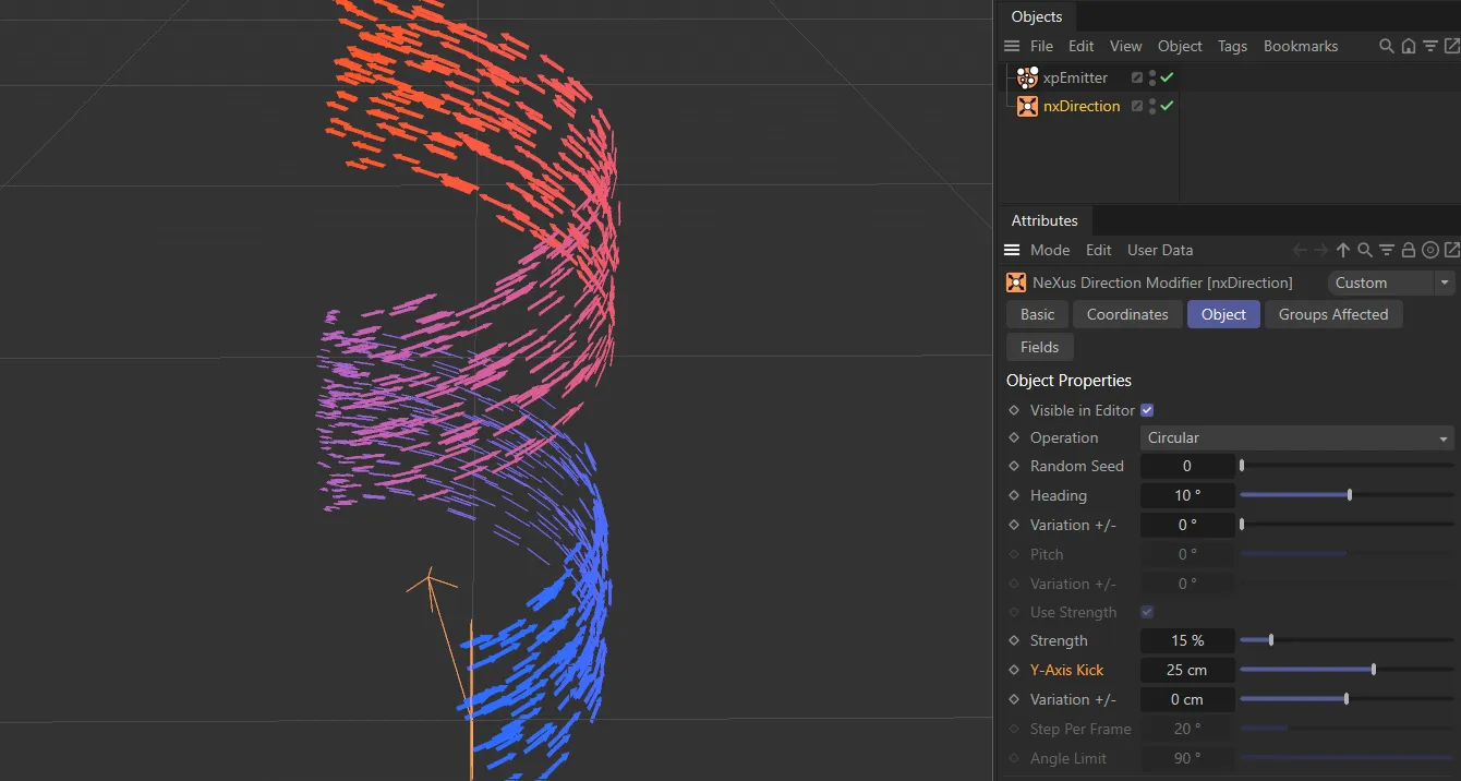
Y-Axis Kick set to 25cm, causing the particles to spiral upwards.
Variation +/-
Section titled “Variation +/-”Allows you to add a random variation to the Y-Axis Kick.
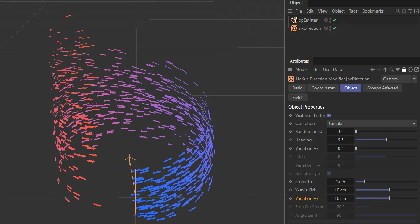
Variation +/- value set to 10cm, to randomise particles in the Y-Axis Kick direction of travel.
Step Per Frame
Section titled “Step Per Frame”Only used in Ring mode, this controls how fast the particles deviate from their current path to the limit given in the Angle Limit setting.
A large number will cause a very rapid change in direction; small numbers will cause a more gradual change.
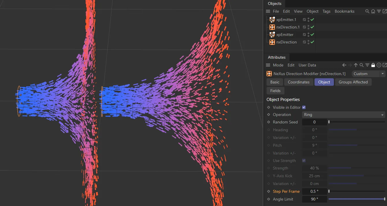
Step Per Frame set with a value of 1 degree on the left and 0.5 degrees on the right.
Angle Limit
Section titled “Angle Limit”Again, only used in Ring mode, it gives the maximum angle by which the particle will deviate from its current path.
The Angle Limit can be set beyond 90°. At 360°, the Loop parameter becomes active.
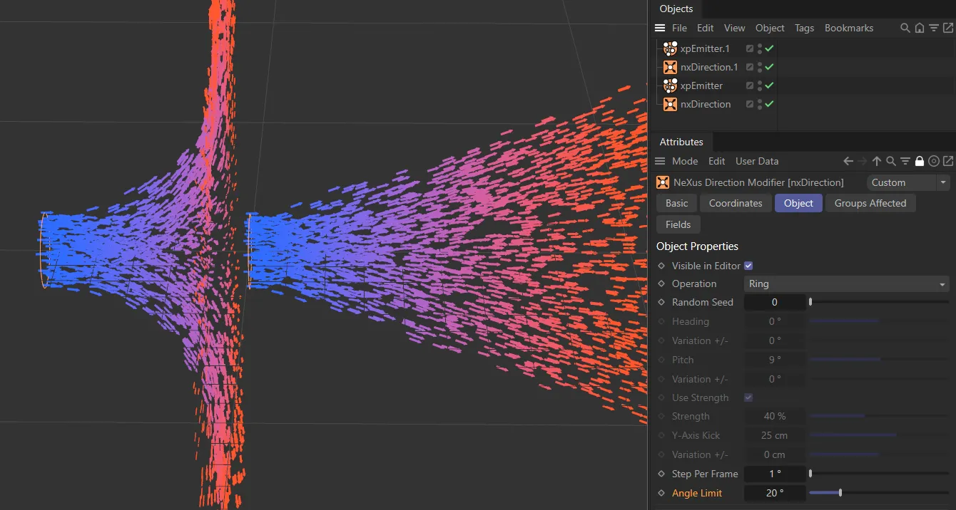
Angle Limit with a value of 90 degrees on the left and 20 degrees on the right.
Limit to Ring
Section titled “Limit to Ring”Controls how strongly particles are constrained to follow the ring path, as a percentage (0–100%).
Higher values pull particles more tightly to the ring.
Only available in Ring mode when Angle Limit is set to 360°.
When enabled, particles that complete a full revolution loop back continuously along their ring path.
Groups Affected tab
Section titled “Groups Affected tab”Groups
Section titled “Groups”To specify the group, drag and drop the desired Group object into this field.
This setting is useful if you want to ensure that the spawned particles are, or are not, affected by nxDirection.
Mapping tab
Section titled “Mapping tab”The modifier’s settings can be mapped to particle data.
Use the dedicated manual page, below, for instructions on how this works.
Fields tab
Section titled “Fields tab”You can use the Fields options to control where nxDirection operates.
Copyright © 2026 INSYDIUM LTD. All Rights Reserved.