tfRiver
tfRiver lets the user create river beds on the terrain.
Streams tab
Section titled “Streams tab”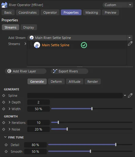
Streams tab default menu settings.
Any number of rivers can be created inside a node tree GUI, with dedicated parameters for each of them.
Add Stream
Section titled “Add Stream”There are three types of rivers available, categorized into ‘Main’ and ‘Secondary’ rivers from this drop-down menu: Main: Settle Spline, Main: Perlin Worm and Secondary: Simple Distribute.
Main rivers can be art directed, and offer an awful lot of control, while secondary rivers are generated on top of the main rivers (like twigs on a tree’s branches), and offer only few parameters.
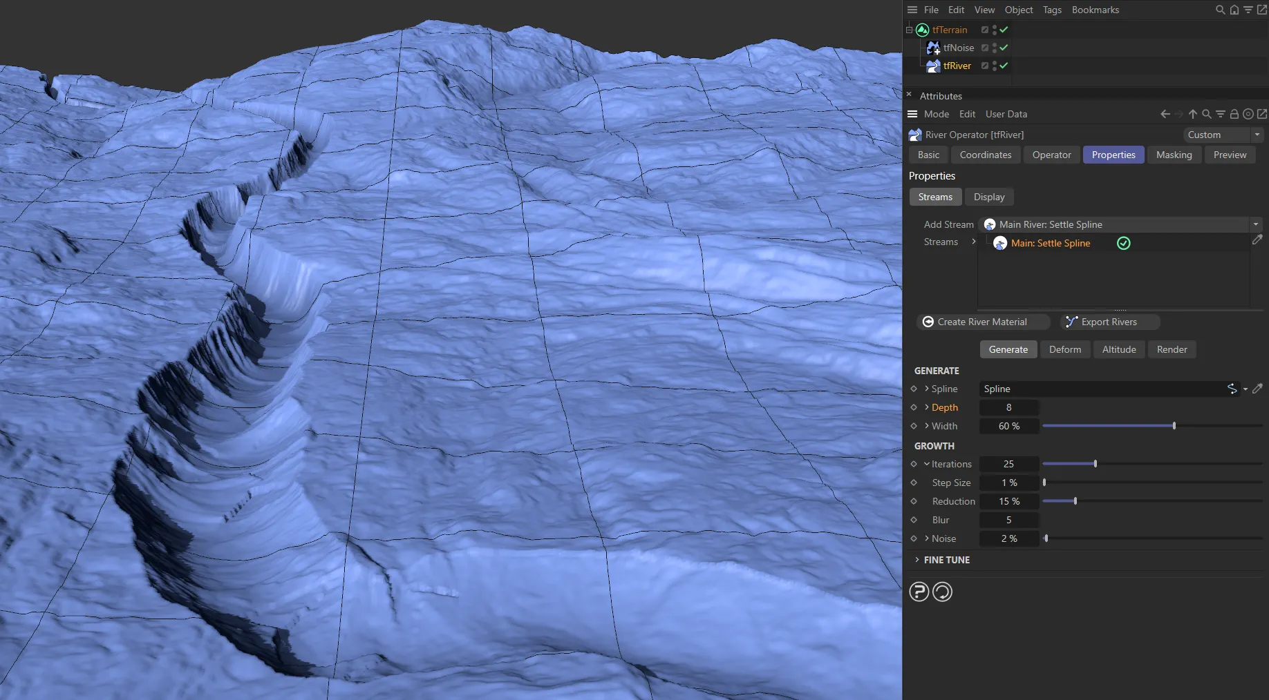
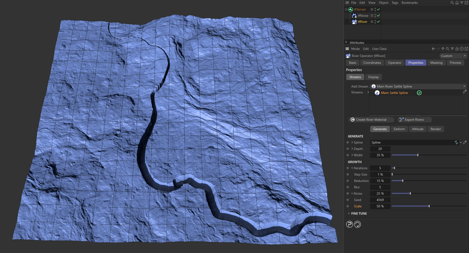
Main: Settle Spline
Section titled “Main: Settle Spline”This approach lets you control the course of the river using a simple spline; the spline can be as detailed or simplistic as you choose.
Iteratively, the spline is resampled, and its points slide downhill, thus settling in valleys and ravines.
The original spline remains untouched and can be edited at any time.
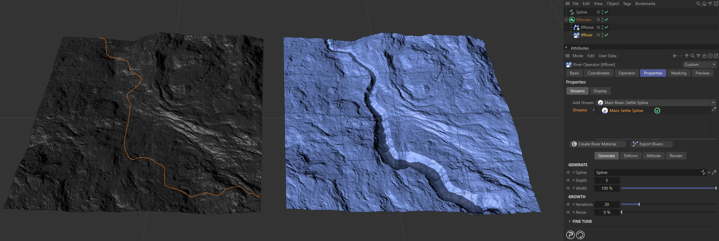
The Main: Settle Spline stream type, with the original spline on the left.
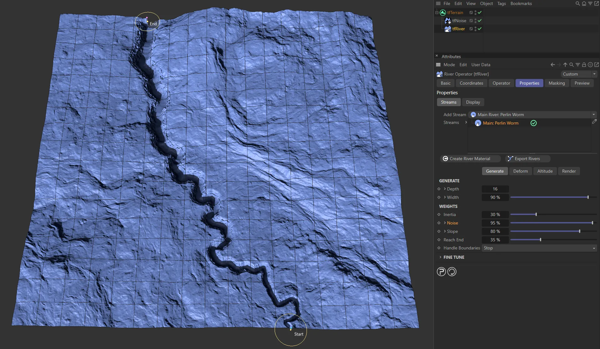
Main: Perlin Worm
Section titled “Main: Perlin Worm”This approach provides a simpler and more simulated workflow.
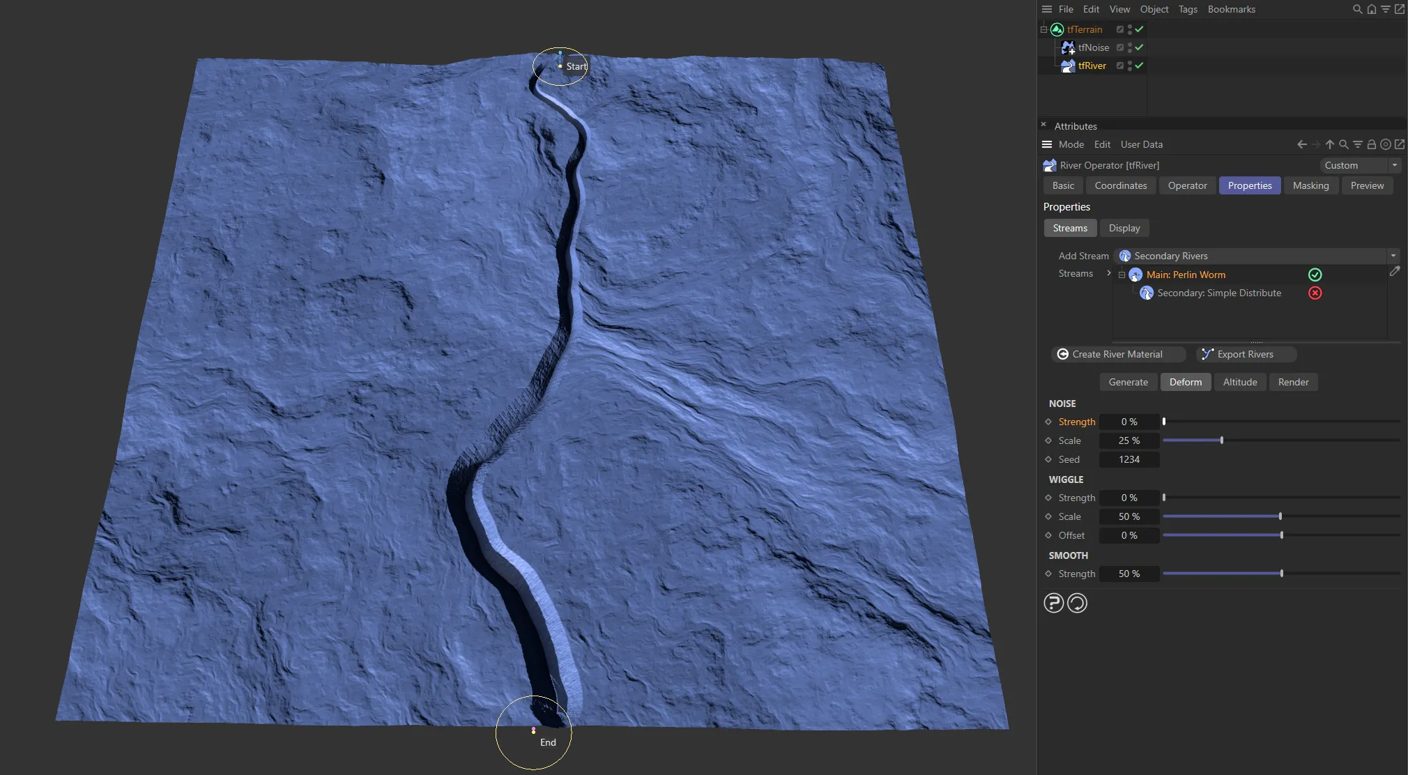
Define a start point (spring) and an end point by dragging around viewport handles and let the river grow between them.
Perlin worms are commonly used in gaming (e.g. Minecraft), where they are grown to generate rivers and caves.
To grow a river from a spring to an end point, the user can set some simple parameters.
A single particle is then simulated, starting from the spring and moving towards the end points, while respecting a set of rules.
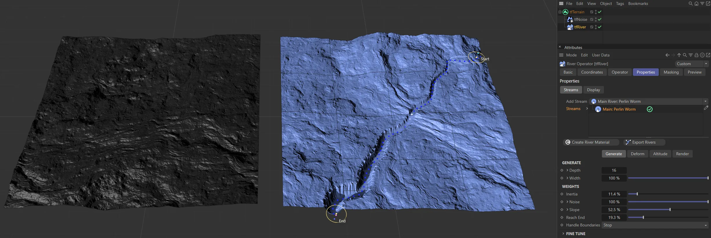
The Main: Perlin Worm stream type, with start and end points highlighted.
tfRiver can also suggest suitable spring and end points; an algorithm finds suitable pairs of a spring and an end point each, to grow a river between by analyzing the input terrain’s local maxima (mountains) and minima (valleys) and then filtering those.
Secondary: Simple Distribute
Section titled “Secondary: Simple Distribute”Multiple secondary rivers are generated, branching from their parent river (which can be a main river or another secondary river node).
The secondary rivers are distributed like twigs on a tree branch; their distribution can be controlled with a Spline curve and there are multiple parameters for length, shape and variation.
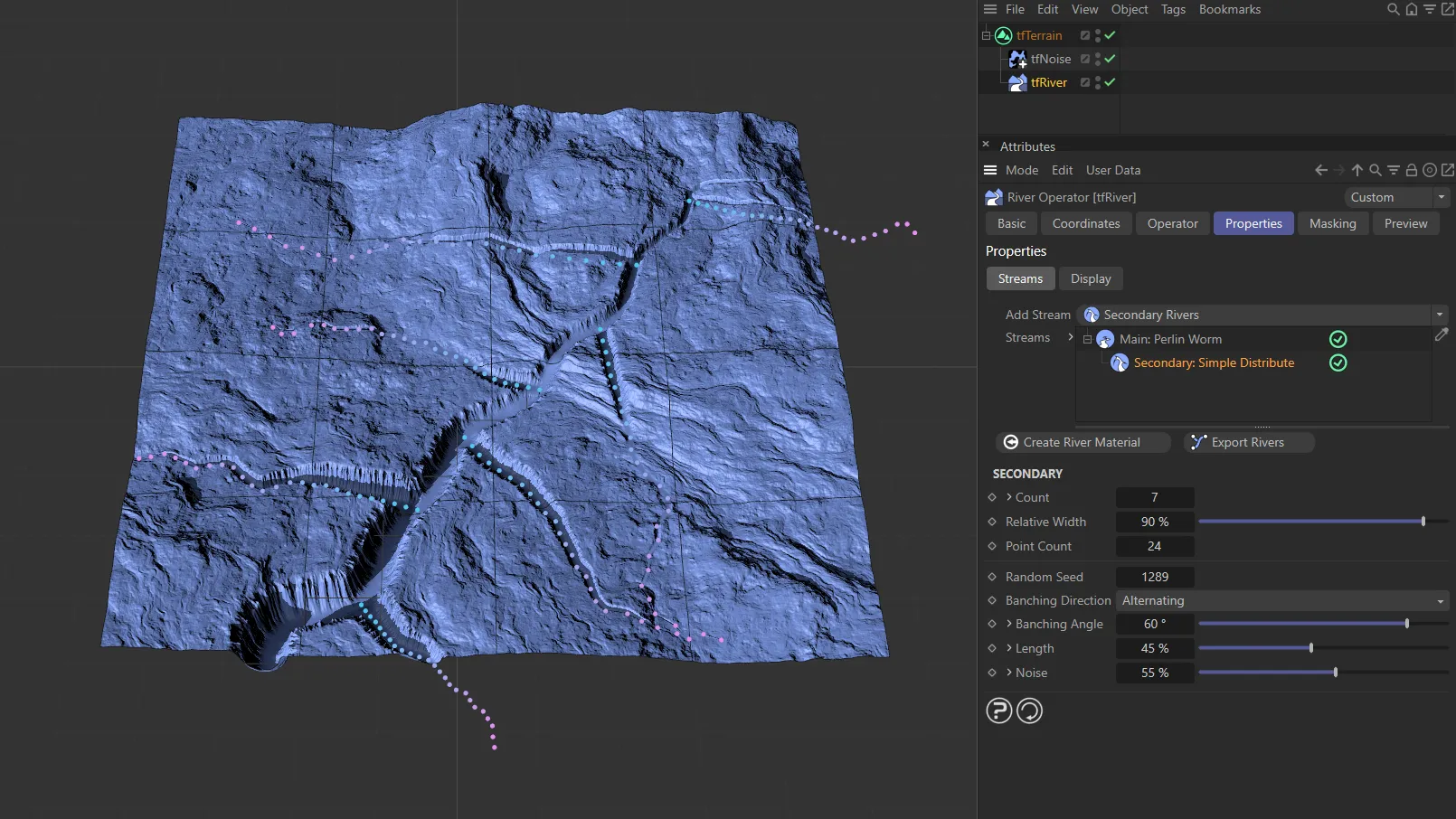
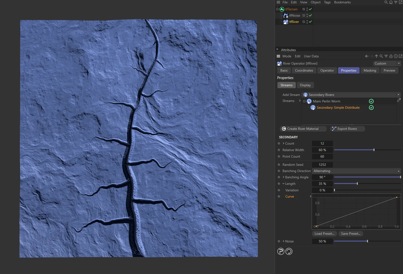
Secondary: Simple Distribute stream type, branching (shown with dots) in several places from the Main: Perlin Worm.
Streams
Section titled “Streams”Node tree list of the streams you have populated your scene with.
This is a hierarchical list, with order being important to the results.
A green tick next to the stream signifies that this stream is enabled.
You can disable the tick, by clicking on it, which changes it into a red cross.
Add River Layer
Section titled “Add River Layer”Clicking this button will create a river material layer, which will automatically be applied to all rivers in your Streams list.
This material layer will contain an Advanced Terrain Shader with a minimal layer setup.
For further information on detailed customization, see the Advanced Terrain Shader page, at the link below.
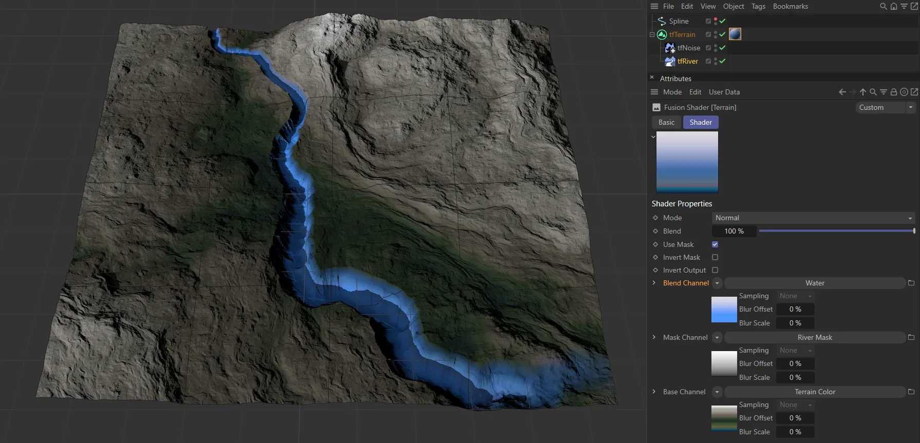
The Add River Layer has been activated here and applied automatically to the river.
This material is placed next to tfTerrain in your Objects Manager and can be amended with the usual Cinema 4D methods.
Export Rivers
Section titled “Export Rivers”Clicking this button will simply export the points of any river that you have created, as a segmented spline.
This will then be placed as a child of tfTerrain, in your objects manager, as tfRiverExport.
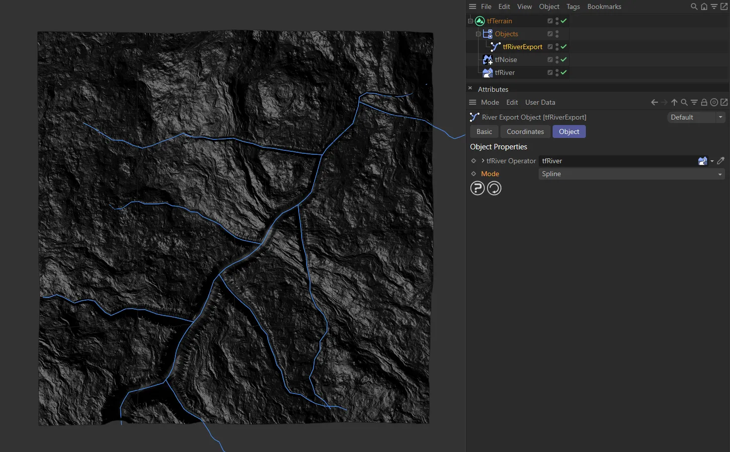
With Export Rivers having been clicked, this image shows the tfRiverExport (explained in a standalone page) User Interface (UI), with the Mode setting as Spline.
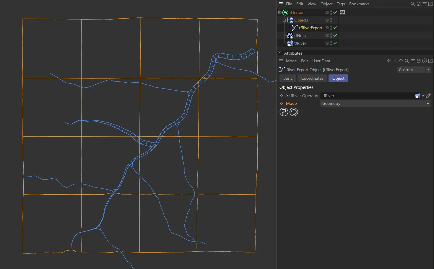
Here, the Mode has been changed to the other setting of Geometry.
Main: Settle Spline settings
Section titled “Main: Settle Spline settings”Generate
Section titled “Generate”Spline
Section titled “Spline”Link a spline here to use it as a template for the river.
This controls how deep the river cuts into the terrain.
Unfold the drop-down arrow to reveal a spline curve that controls the depth along the length of the river.
Depth setting of 8.
Here, the Depth is increased to 30.
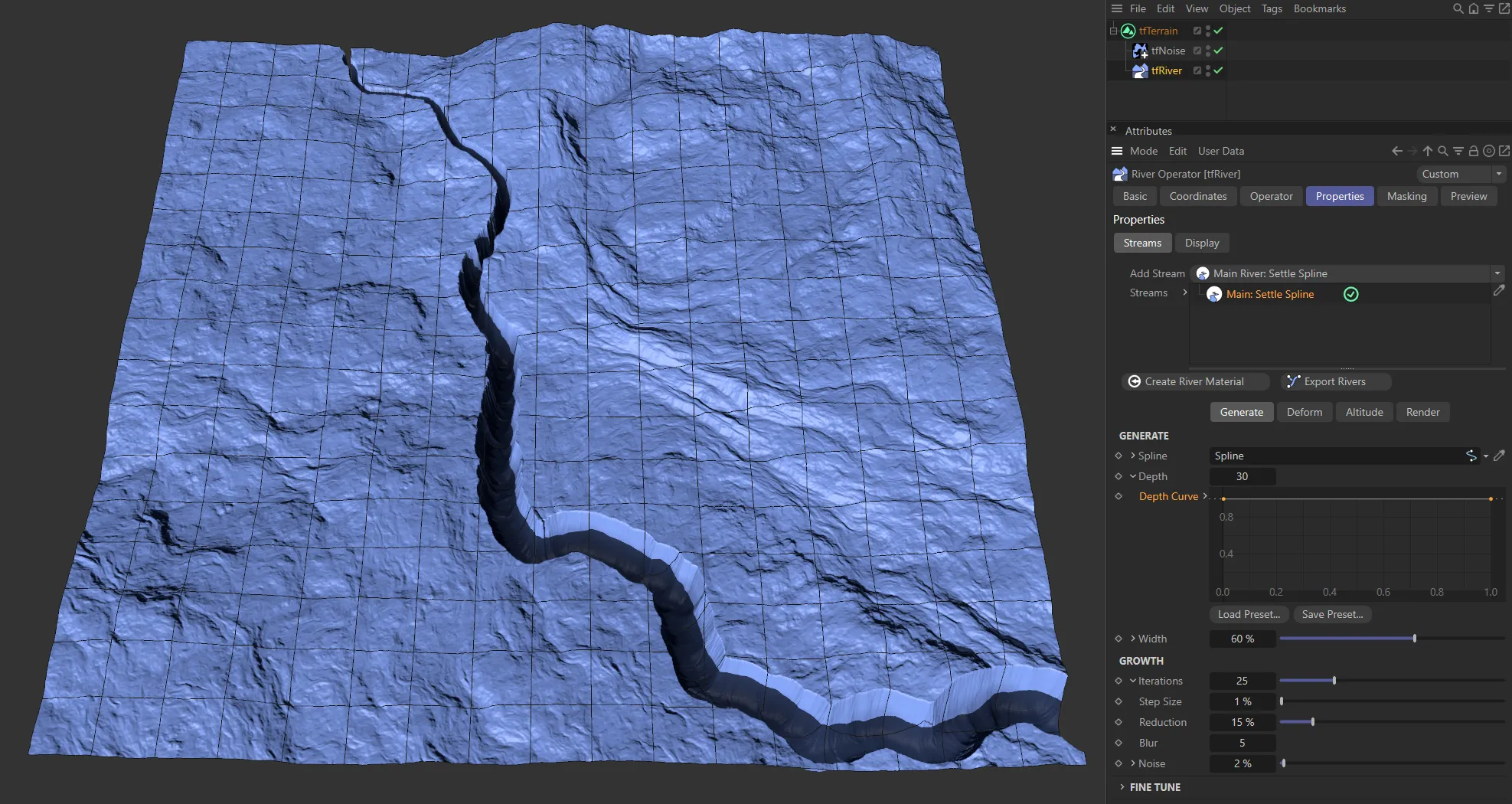
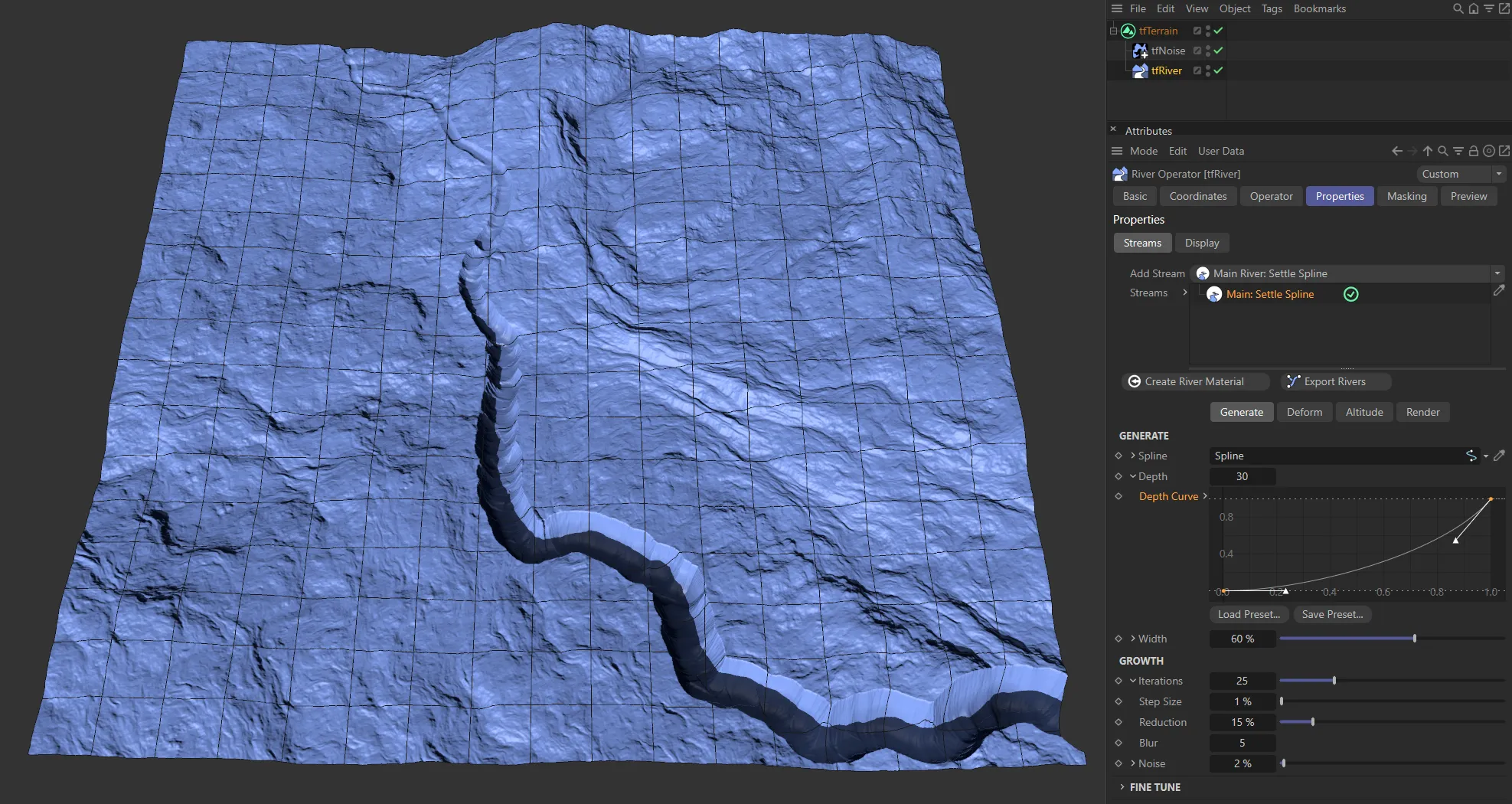
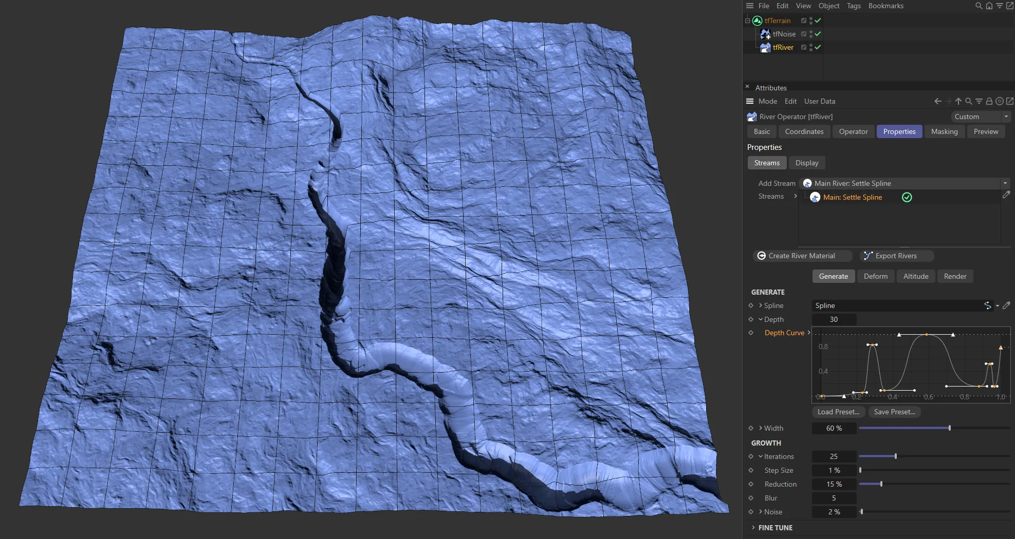
In these three images, three different Depth Curve spline settings are driving the depth along the length of the rivers.
This controls the maximum width of the river.
Unfold the drop-down arrow to reveal a spline curve that controls the width along the length of the river.
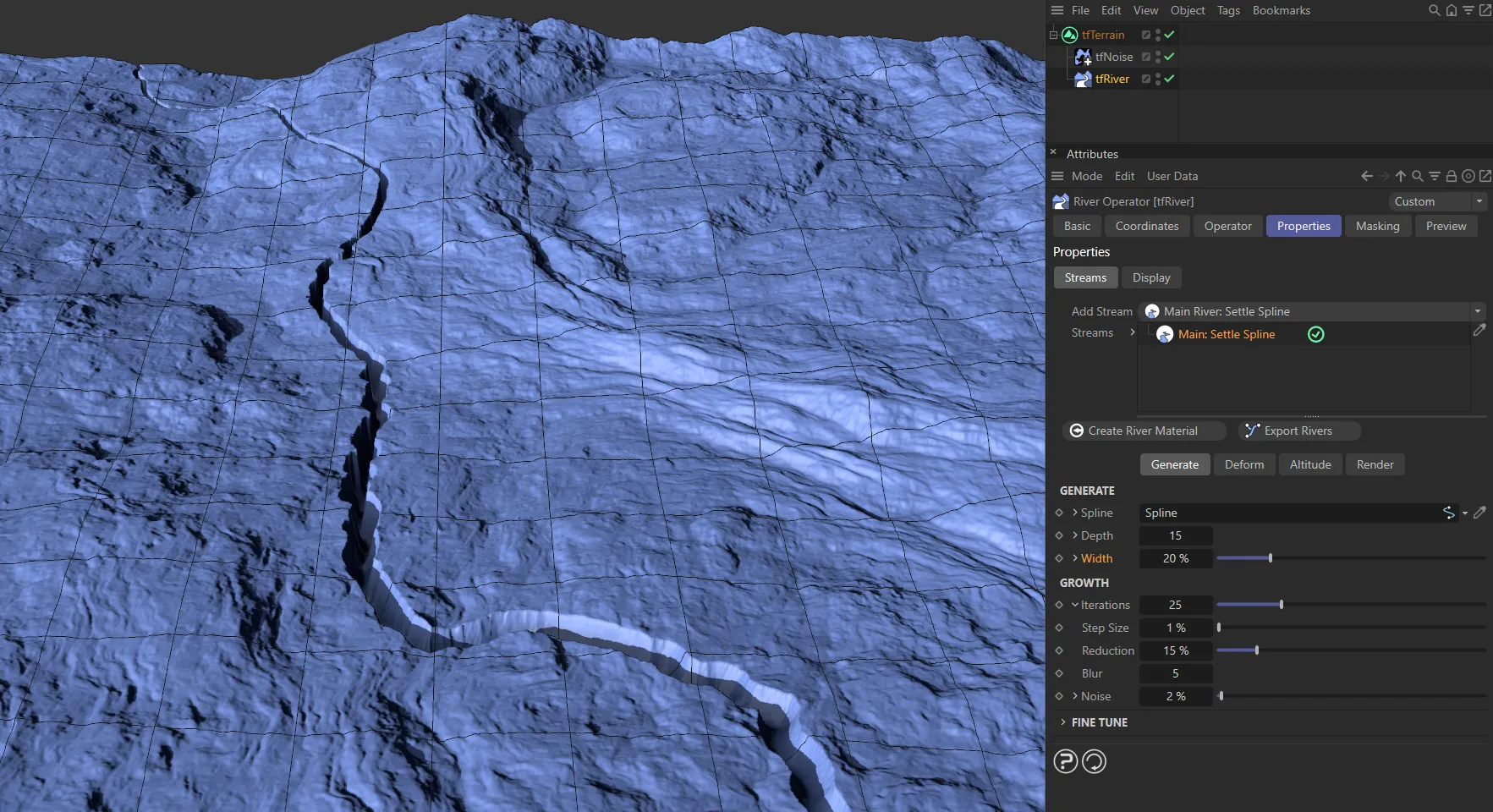
Here, a Width value of 20% is shown.
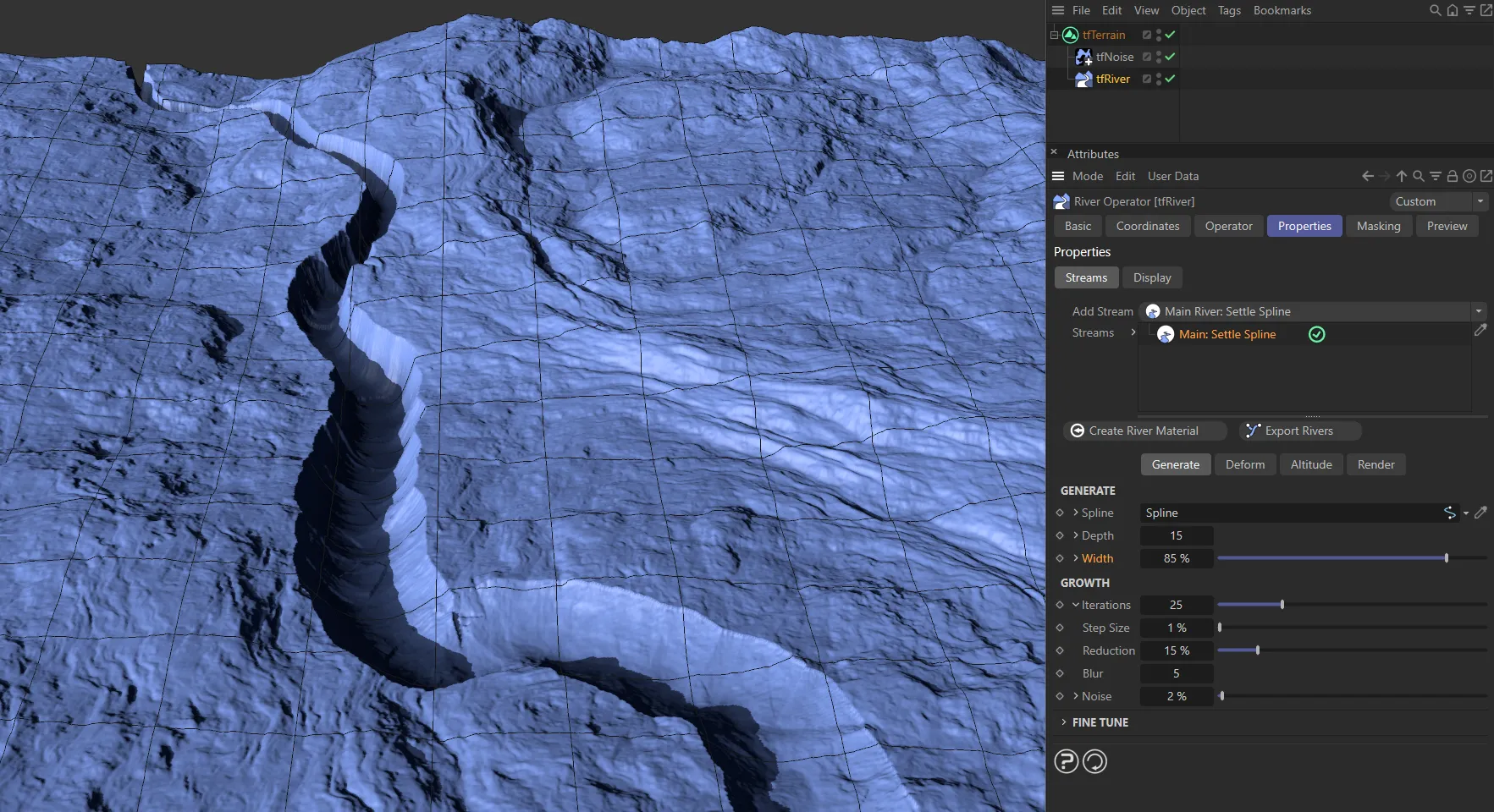
In this image, the Width is increased to 85%.
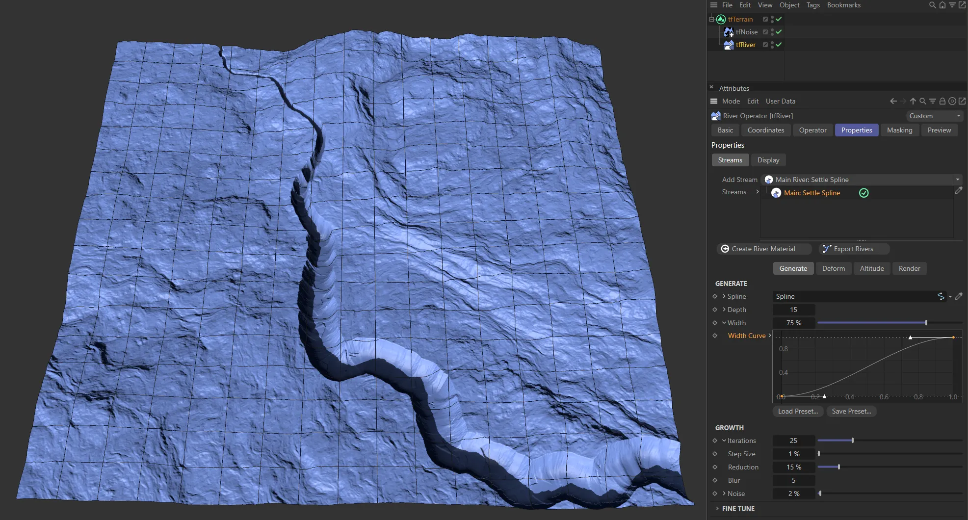
An ‘ease-ease up’ Width Curve spline setting driving the width along the length of the river.
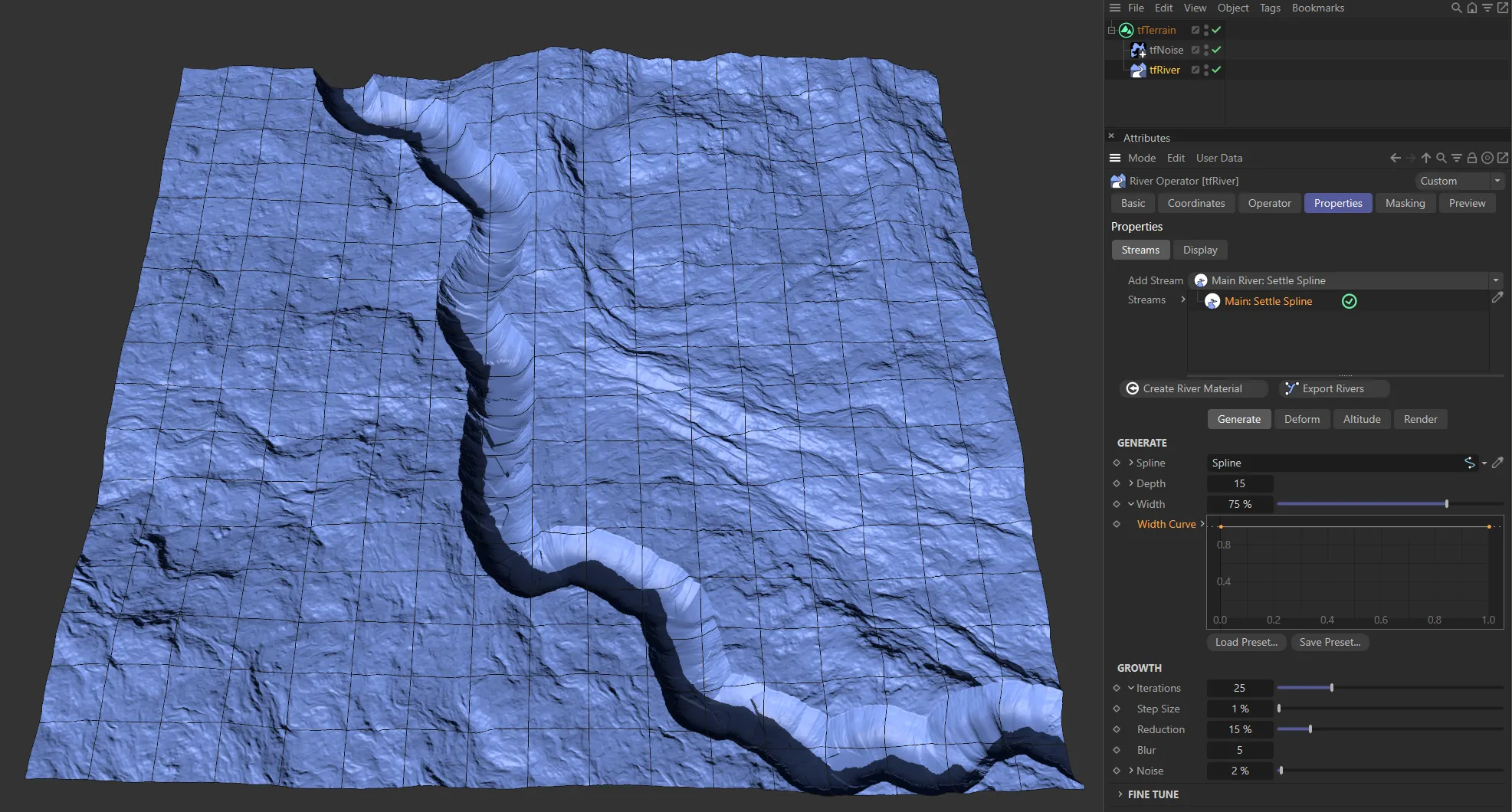
In this image the Width Curve has a full strength spline, giving a consistent length.
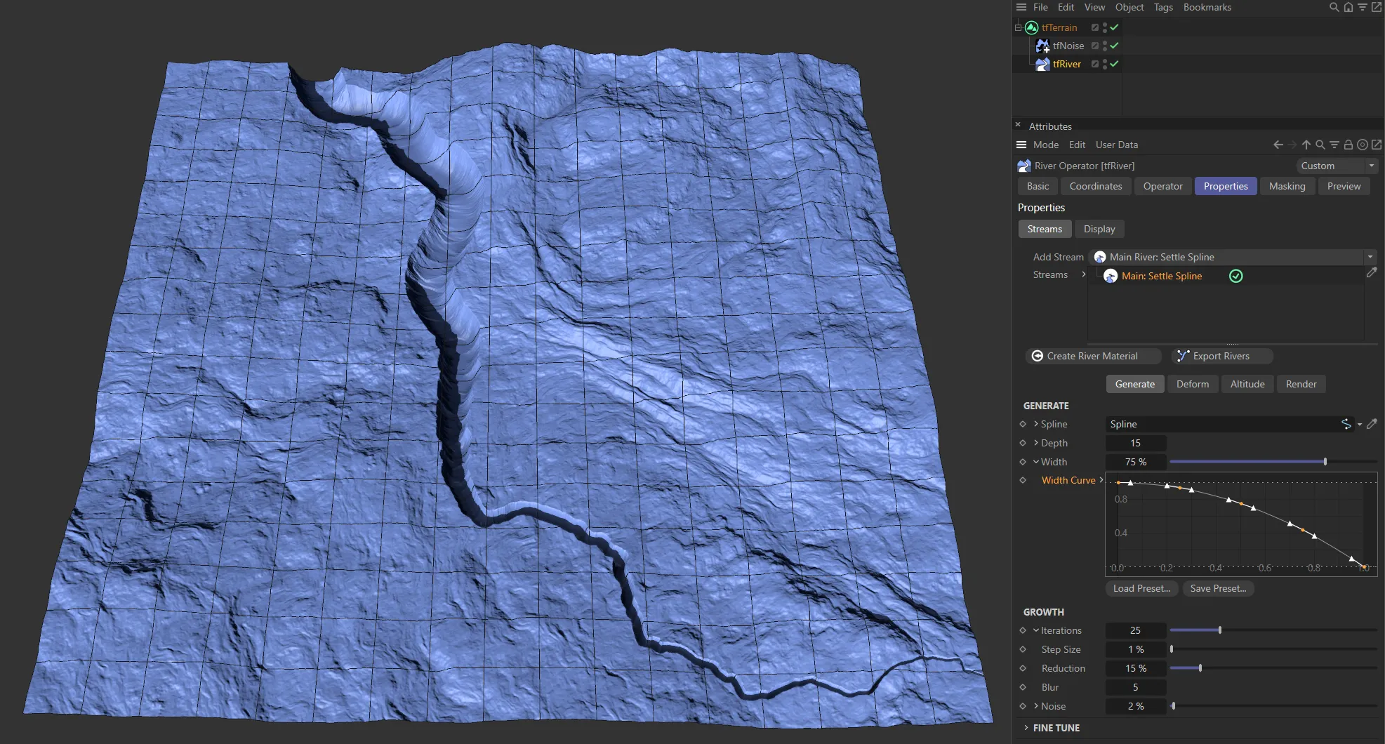
Finally, an ‘inverse’ spline, gives this different look at the river length.
Growth
Section titled “Growth”These parameters control the river path.
Iterations
Section titled “Iterations”The number of iterations to compute.
With each iteration, the spline points are settled downhill by Step Size.
Unfolding the drop-down arrow will reveal three additional attributes.
Step Size
Section titled “Step Size”The distance (in Terrain Grid UV units) by which the spline points are moved downhill during each iteration.
Reduction
Section titled “Reduction”Increasing this value will effectively use a downscaled version of the input terrain grid for the Main: Settle Spline stream computations.
The greater the value, the less that insignificant details will be considered.
Use this attribute to apply additional blur to the down-sampled grid.
Increase this value to have the river path more affected by a noise field.
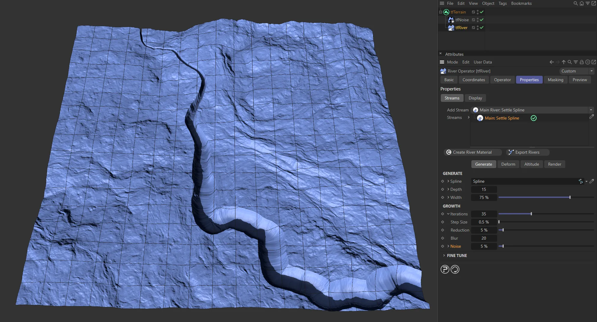
A Noise value of 5%.
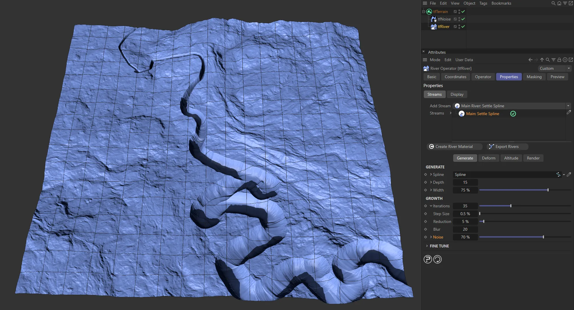
Here, the Noise has been increased to 70%.
Unfold the drop-down arrow to reveal two additional parameters.
The random start value.
Each change in value will result in a completely different noise result.
Scales the noise.
Larger values will make the river wind more smoothly.
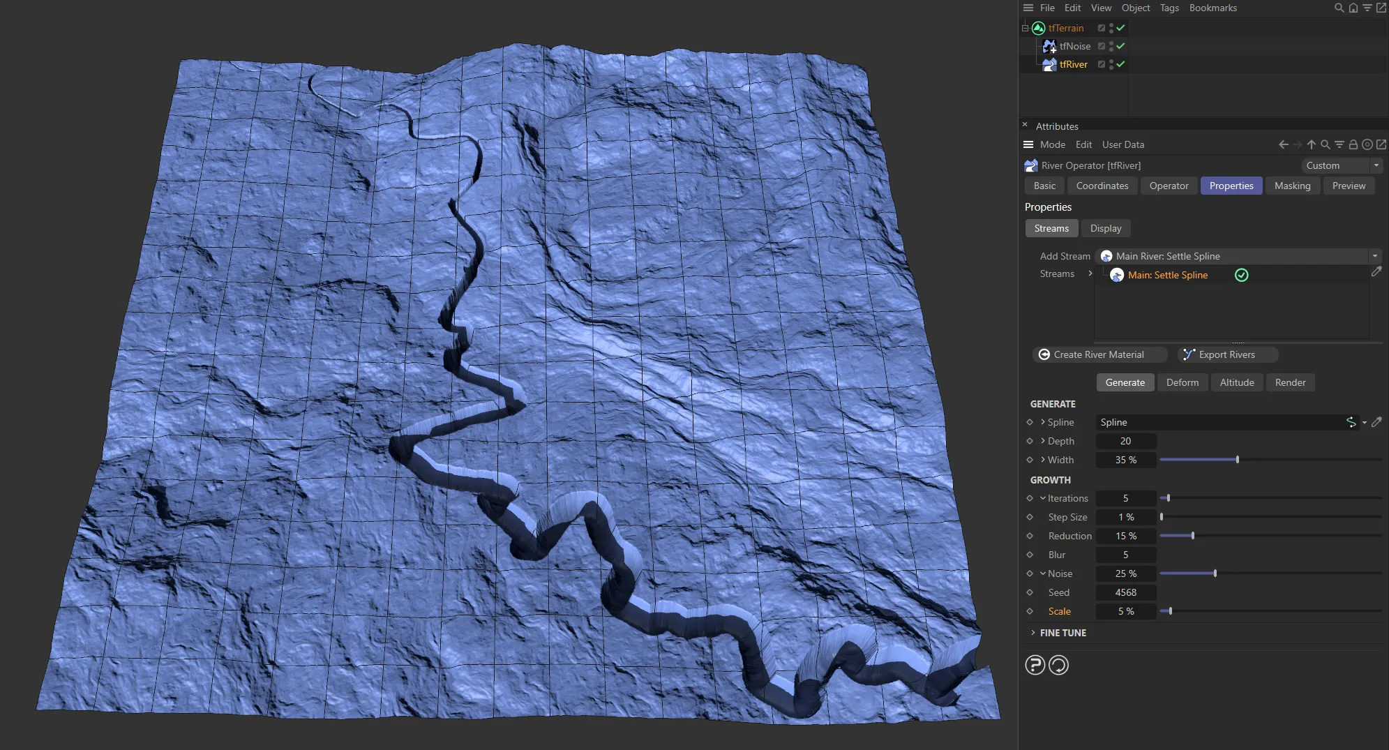
A 5% Scale setting.
Scale raised to 50%.
Fine Tune
Section titled “Fine Tune”These attributes will tweak the look of the river path.
Detail
Section titled “Detail”This attribute controls the point density of the river (applied in the resampling stage after each iteration).
Larger values will make sharp bends smoother but also generally create more points for details.
Smooth
Section titled “Smooth”Increase this attribute to smooth out unwanted sharp bends in the river.
Main: Perlin Worm settings
Section titled “Main: Perlin Worm settings”Generate
Section titled “Generate”This controls how deep the river cuts into the terrain.
Unfold the drop-down arrow to reveal a spline curve that controls the depth along the length of the river.
This controls the maximum width of the river.
Unfold the drop-down arrow to reveal a spline curve that controls the width along the length of the river.
Weights
Section titled “Weights”On its way from the start towards the convergence point, a Perlin Worm evaluates certain rules to decide where to move next.
The intensity of each rule’s effect is controlled using these weights.
As is so often the case with simulations, slight changes to the parameters can have a big effect.
Inertia
Section titled “Inertia”Defines how much the worm will try to keep its current direction.
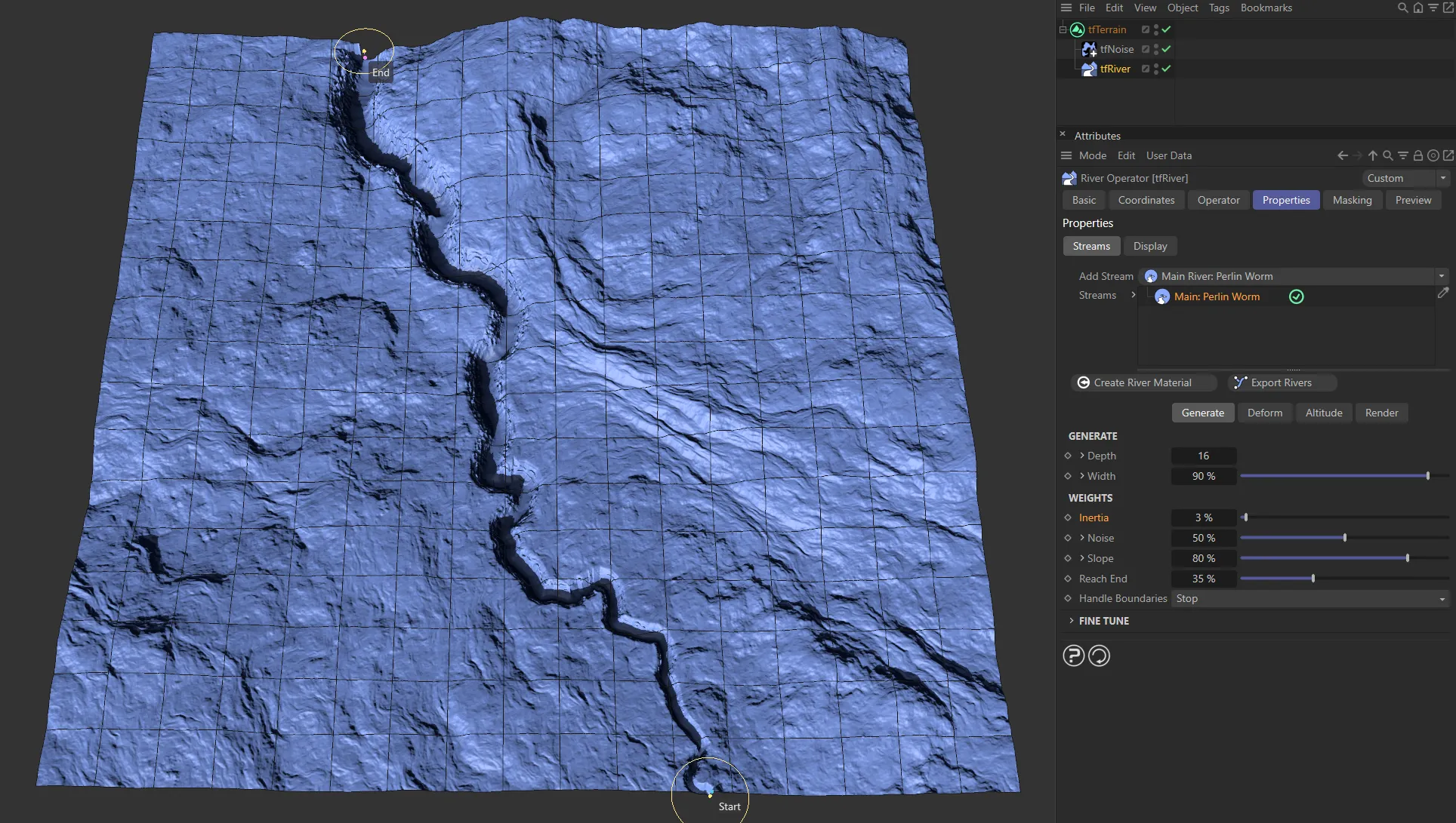
Inertia set at 3% with the Main: Perlin Worm stream.
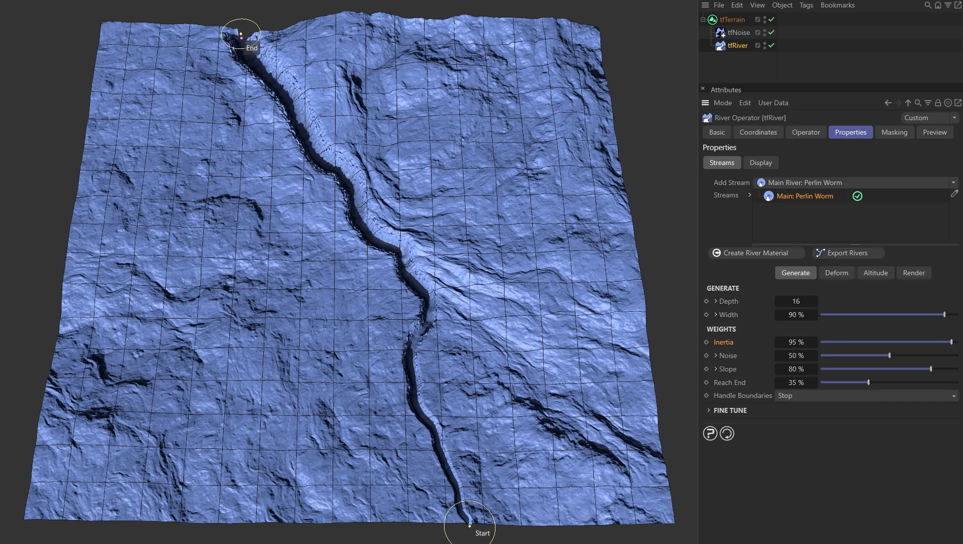
Inertia raised to 95%.
Defines how much the worm is affected by the Perlin noise.
Unfold the drop-down arrow to reveal four additional parameters.
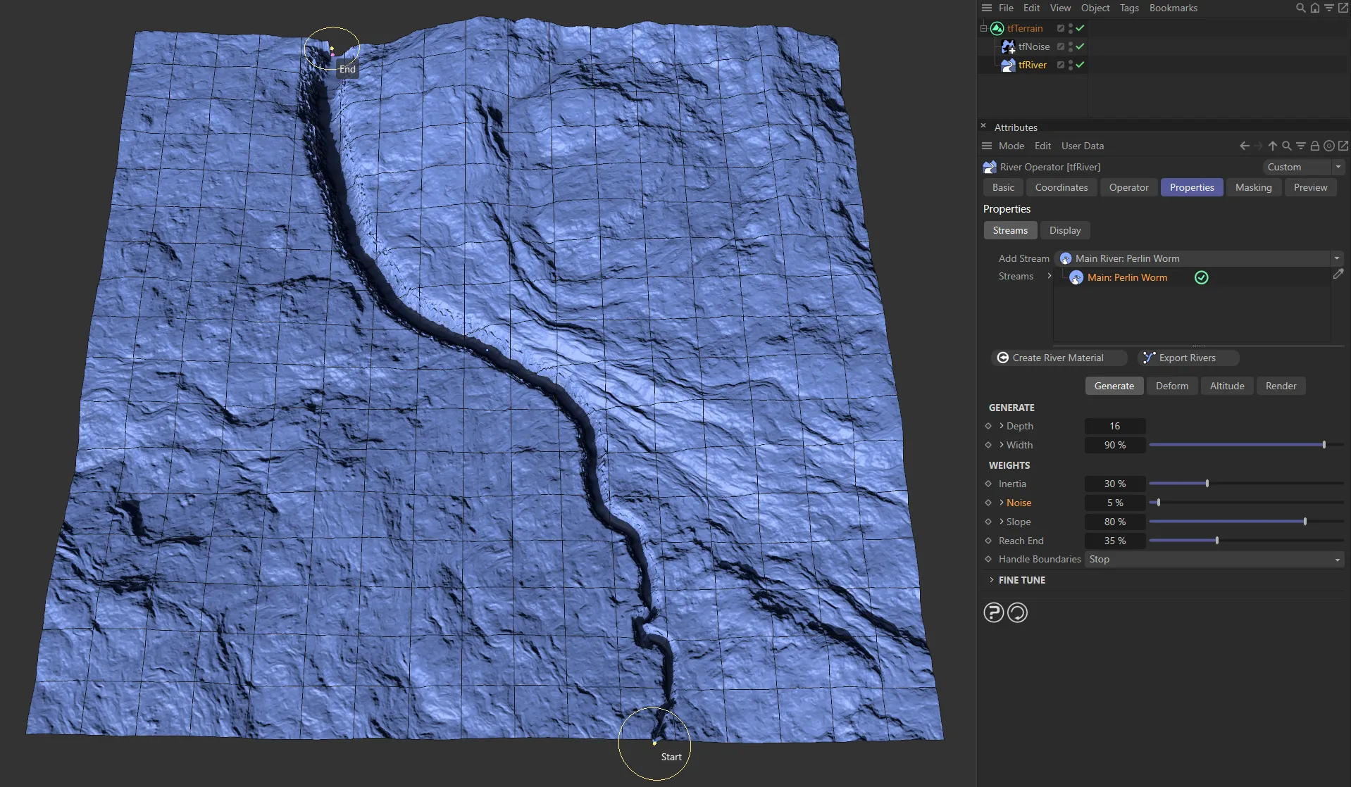
Here, the Noise setting is at only 5%.
And here, it has been increased to 95%.
Random start value.
Each value will result in a completely different noise result.
Offset
Section titled “Offset”Moves the Perlin noise in each axis, creating different variations.
Scales the noise.
Larger values will make the river wind more smoothly.
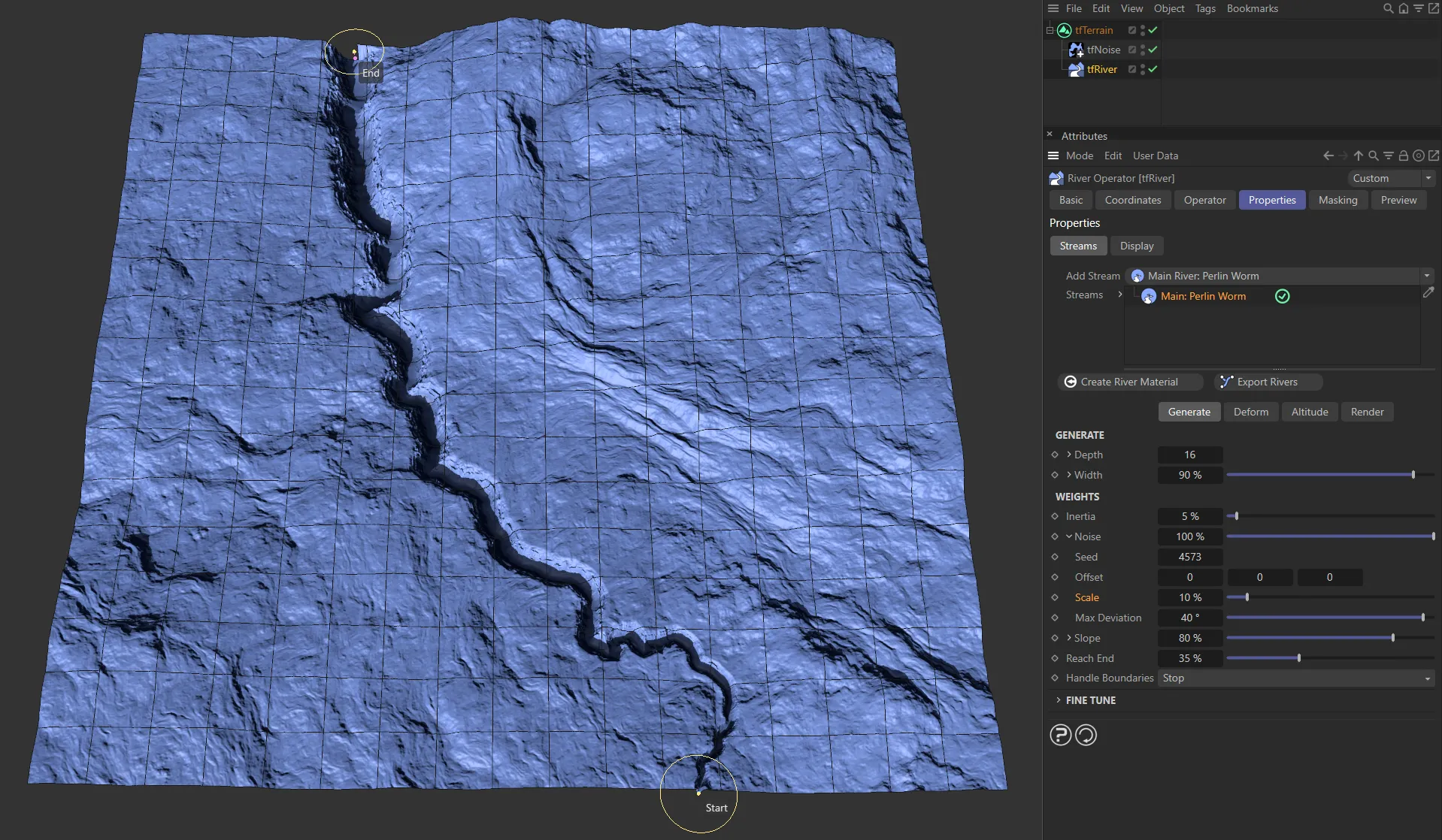
Scale value of 10%.
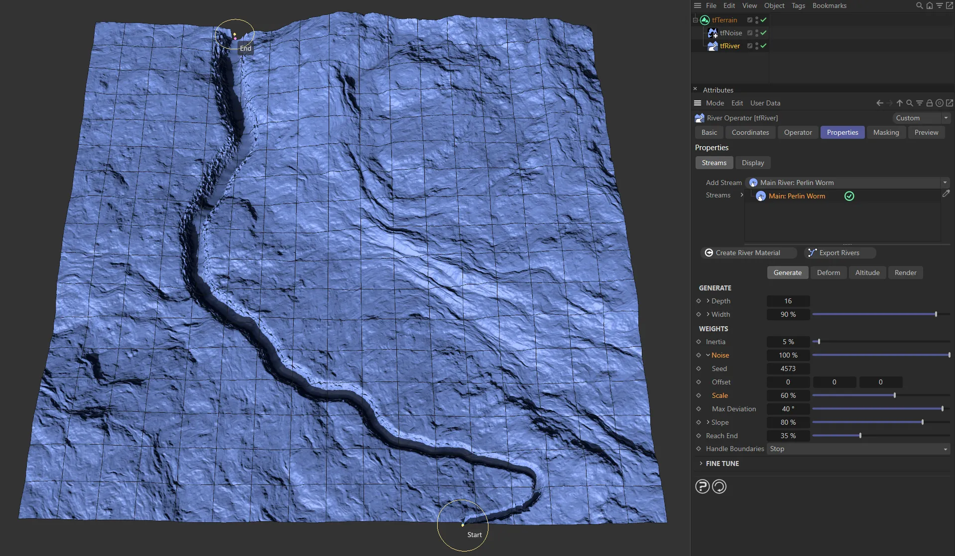
With the Scale raised to 60%, the river winds in a smoother pattern.
Max Deviation
Section titled “Max Deviation”This limits the deviation that noise causes.

Here, there is a Max Deviation, from the noise, of 40%.
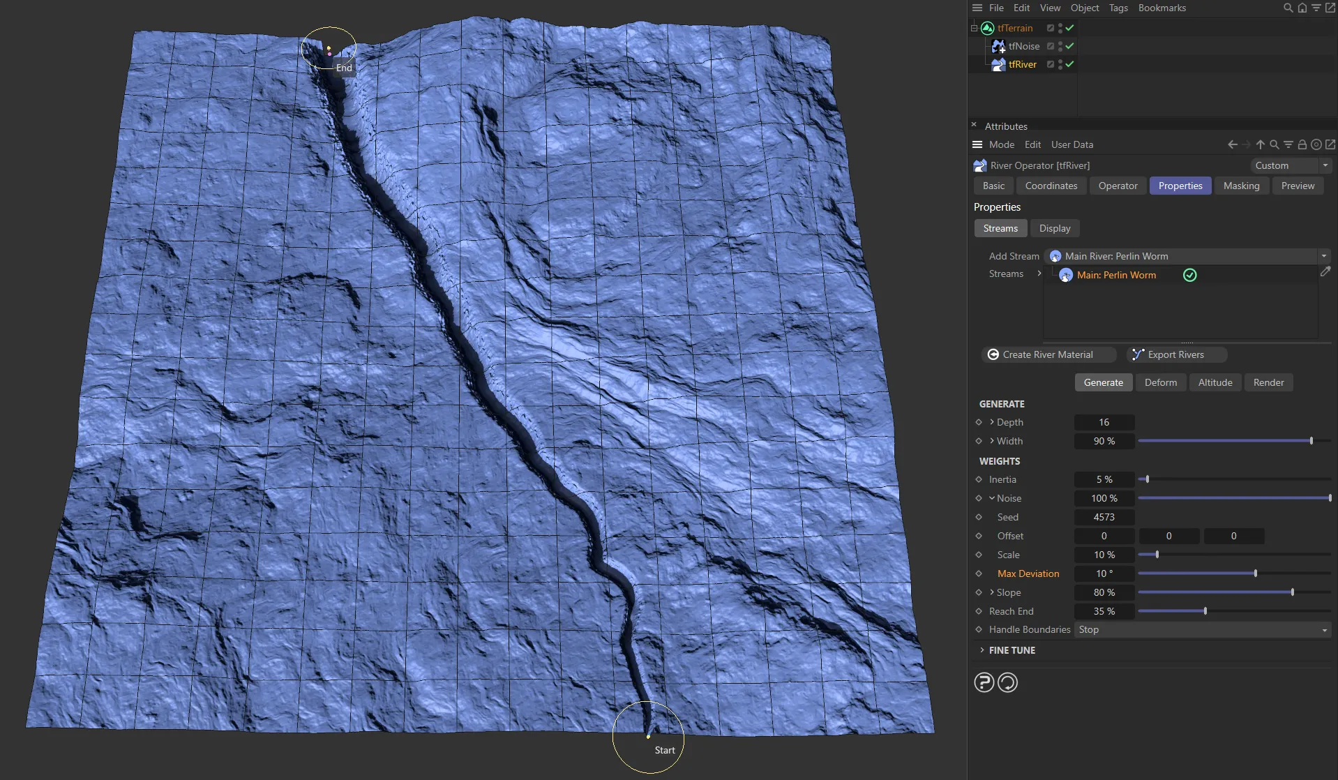
Lowered to only 10%, in this image.
Controls how much the worm will want to move downhill.
Unfold this drop-down arrow to reveal an additional parameter.
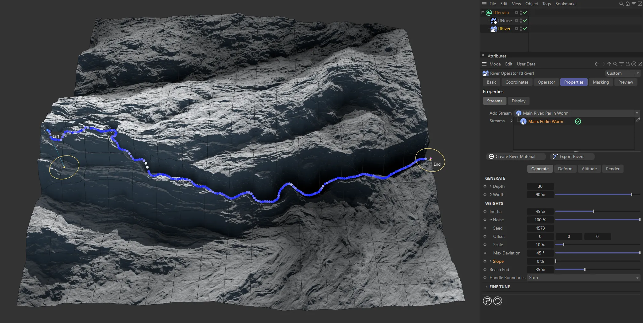
There is no Slope value in this image.
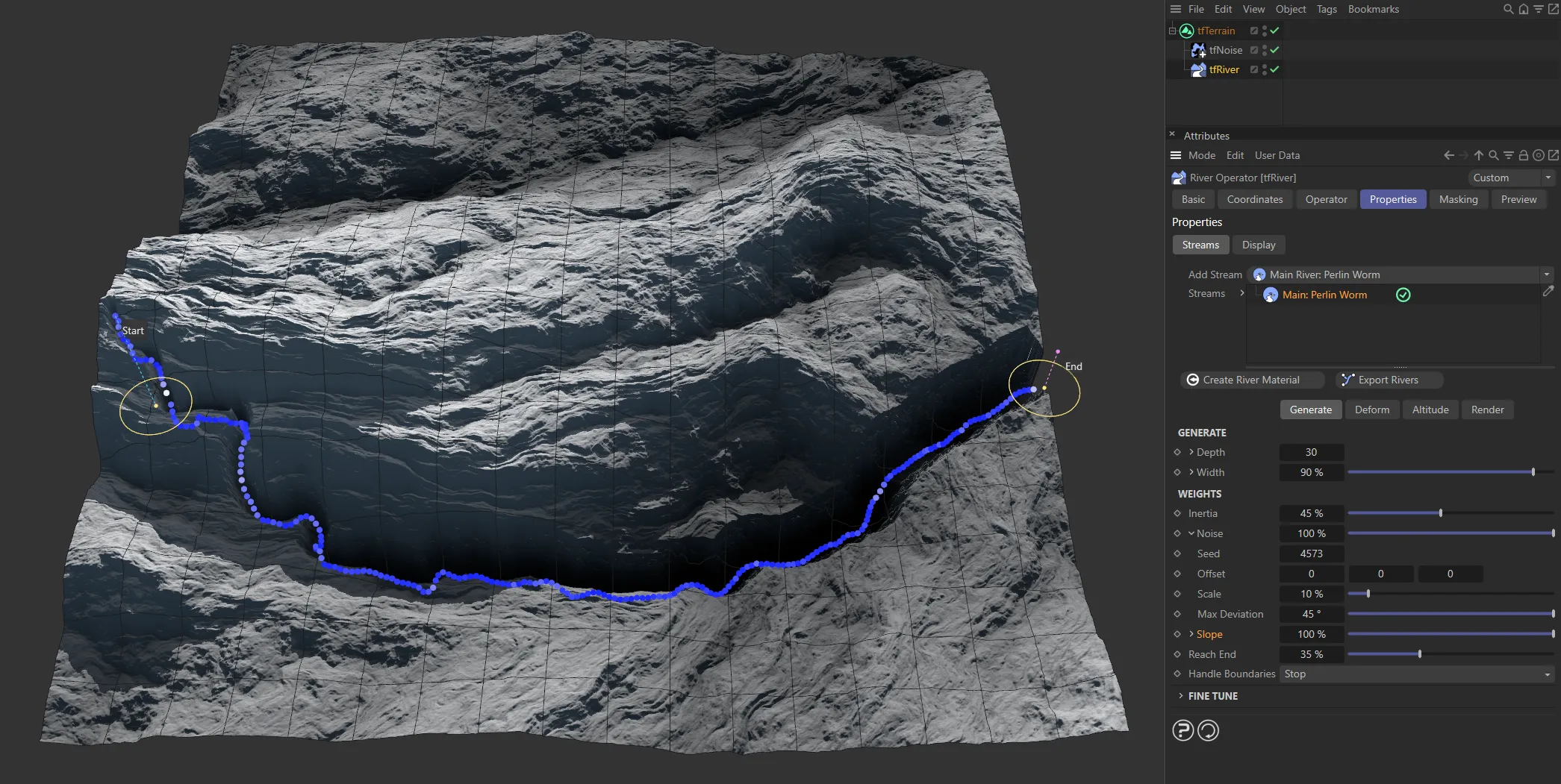
Showing a clear difference, when the Slope value is raised to 100%.
Simplify Grid
Section titled “Simplify Grid”Down-sample the grid used for sampling slope values.
Effectively, increasing this value will make the Perlin Worm react less to smaller terrain details.
Reach End
Section titled “Reach End”Controls how strongly the worm is attracted by the river end point.
Handle Boundaries
Section titled “Handle Boundaries”Set as Stop, by default, this set what will happen when the Perlin Worm encounters a terrain boundary.
The alternative is None.
Nothing happens, the worm just keeps on growing in that direction.
The worm stops growing at the terrain boundary.
Fine Tune
Section titled “Fine Tune”Use these attributes to tweak the look of the river path.
Max Steps
Section titled “Max Steps”The maximum number of steps the Perlin Worm is simulated for.
The actual number of resulting steps may be lower if the particle reaches its end point earlier.
Step Size
Section titled “Step Size”The distance (in Terrain Grid UV units) by which the spline points are moved downhill during each iteration.
Lower values will result in a more detailed river path.
Smooth
Section titled “Smooth”Increase this attribute to smooth out unwanted sharp bends in the river.
Optimize
Section titled “Optimize”If your Perlin Worm river has too many unwanted, sharp bends or tends to kink in some places, carefully use this parameter to get rid if those issues.
Secondary: Simple Distribute settings
Section titled “Secondary: Simple Distribute settings”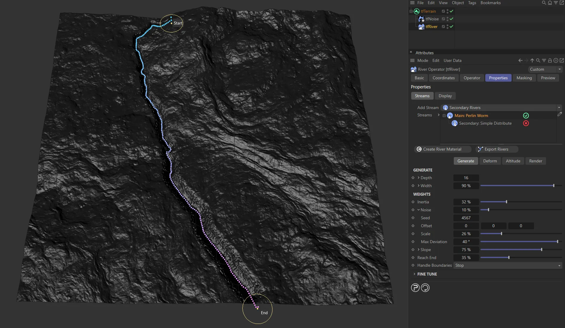
In this image, the Main: Perlin Worm stream is visible.
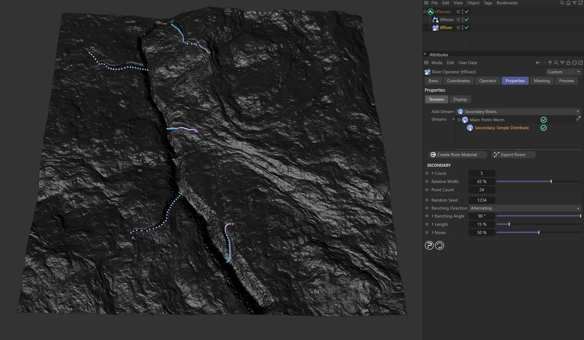
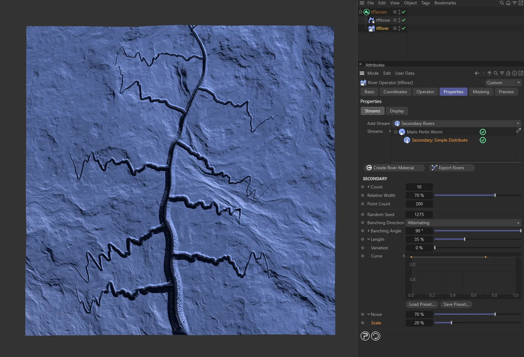
Here, the Secondary: Simple Distribute stream (marked with dots) has been enabled, adding it to the Main: Perlin Worm.
The number of secondary rivers that are branched from the parent river.
By default, the secondary rivers will be distributed evenly along the parent river.
Unfold to reveal the following, three additional distribution parameters.
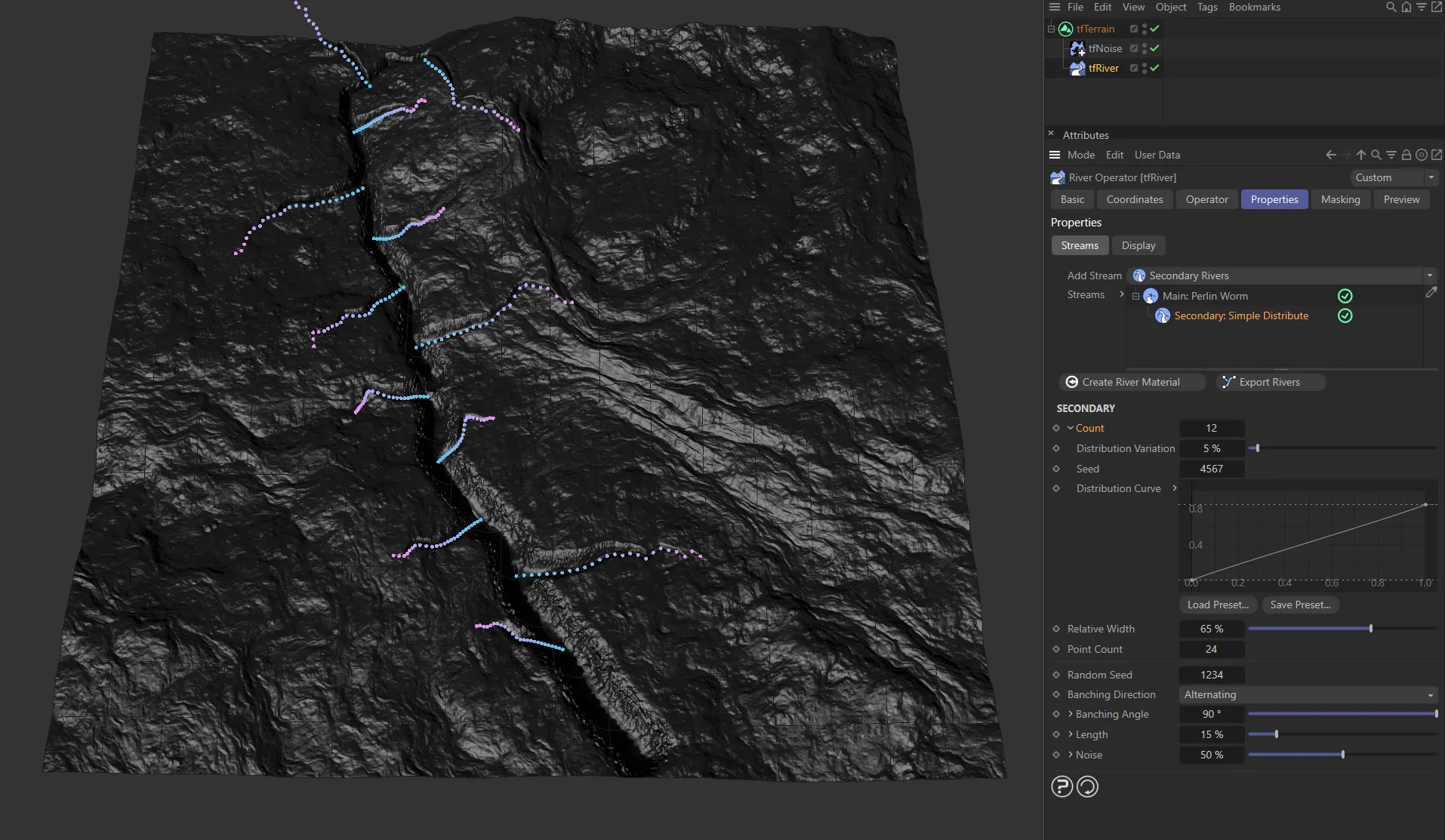
There are 12 secondary rivers here, driven by the Count setting.
Distribution Variation
Section titled “Distribution Variation”Applies randomness to the otherwise regular distribution of secondary rivers along the parent river.
The random start value for Distribution Variation.
Each possible value will create a different distribution result.
Distribution Curve
Section titled “Distribution Curve”This curve gives you direct manual control about the distribution.
Relative Width
Section titled “Relative Width”A multiplicator that controls each secondary river’s width, relative to the parent river’s width at the branching point.
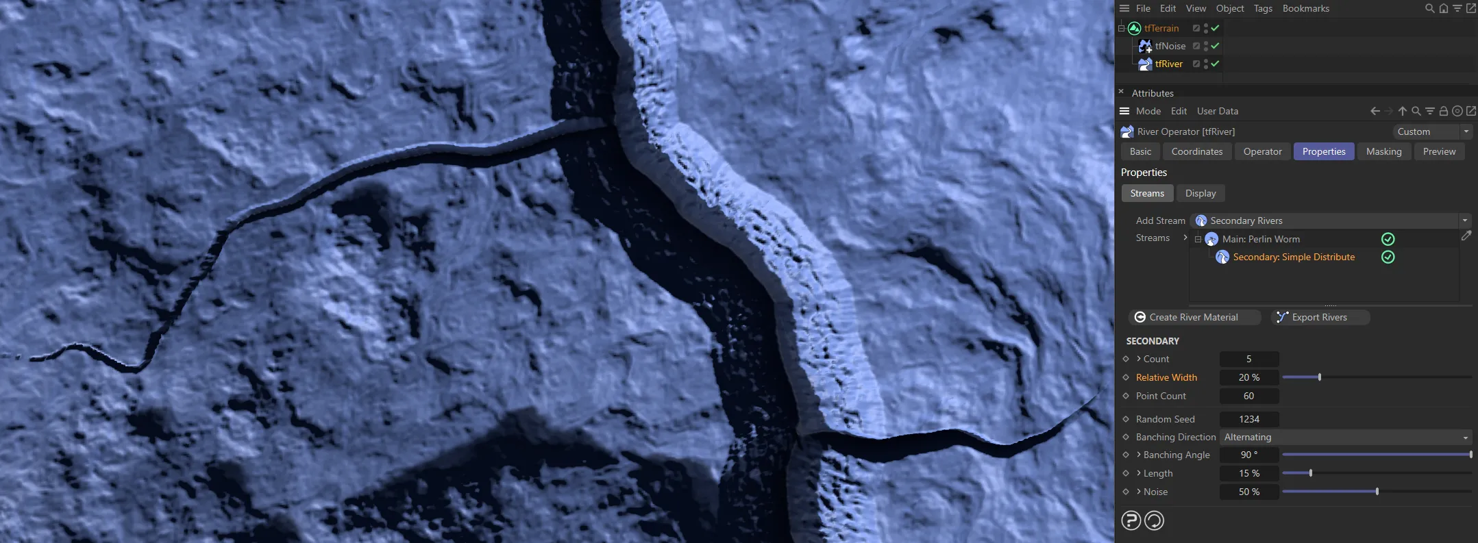
In this image, the Relative Width is 20% of the parent river’s width at the branching point.
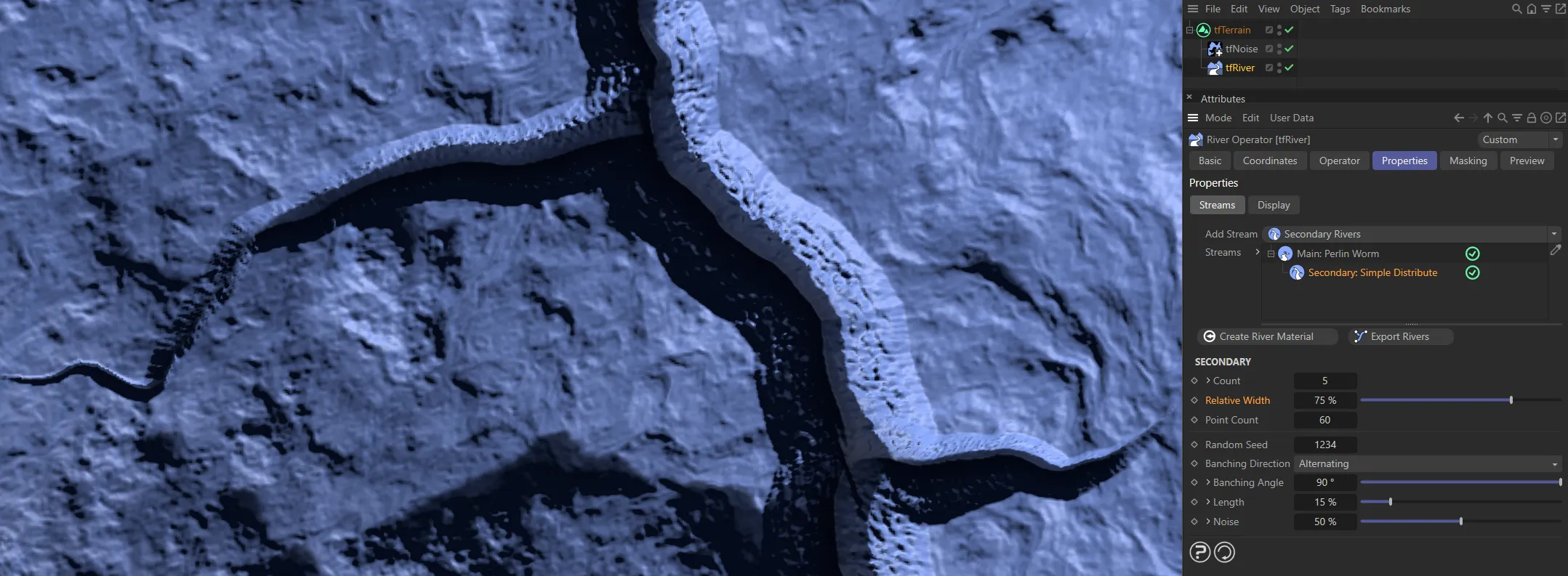
Here, it has been raised to 75%.
Point Count
Section titled “Point Count”The number of points used for each branching, secondary river.
Random Seed
Section titled “Random Seed”The random start value for all river paths.
Each possible value will create a totally different result.
Branching Direction
Section titled “Branching Direction”Set as Alternating, by default, this controls the direction of secondary rivers, branching from the parent river.
The other options are: Same and Random.
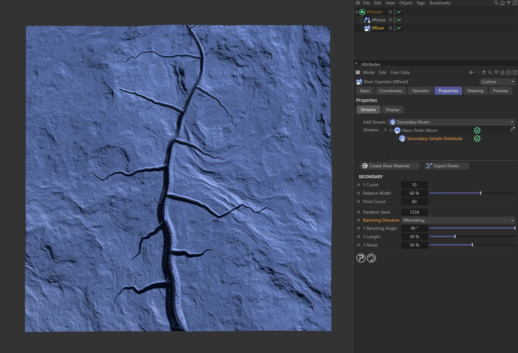
Branching Direction is set as Alternating.
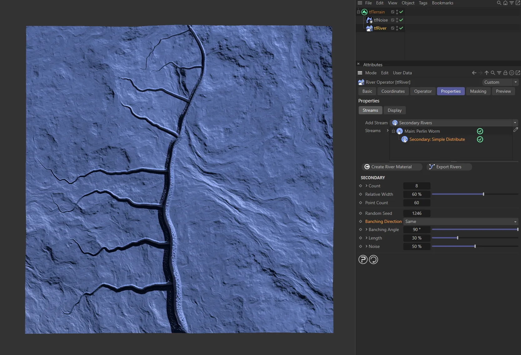
Here, the Branching Direction is Same, with all secondary rivers branching off at the same side.
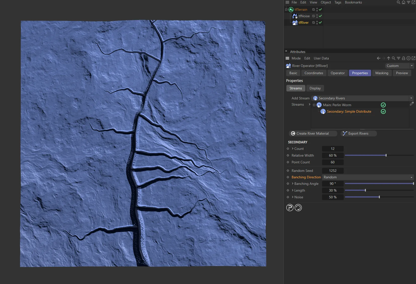
This final setting is Random, giving a random, natural look.
Branching Angle
Section titled “Branching Angle”Controls the angle of the branching secondary river, from the parent river.
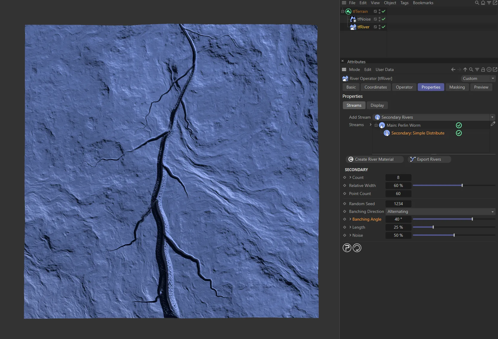
Branching Angle of 40 degrees.
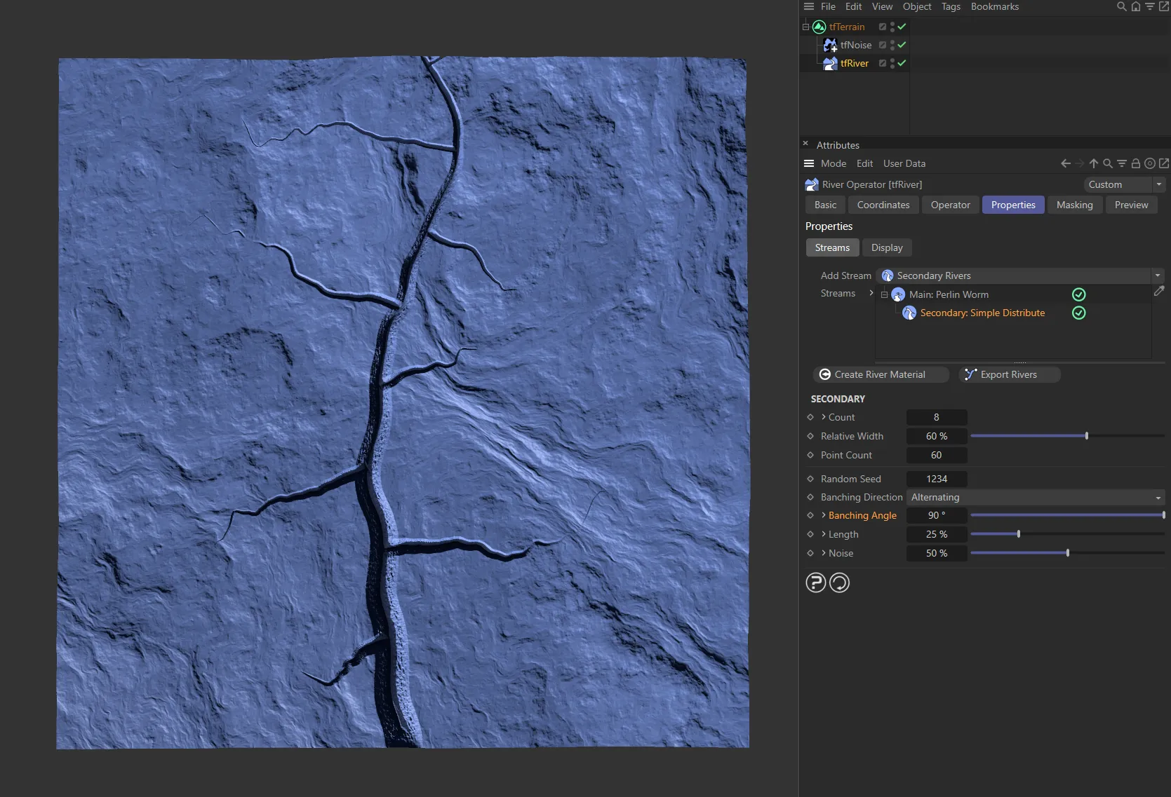
Here it is raised to 90 degrees.
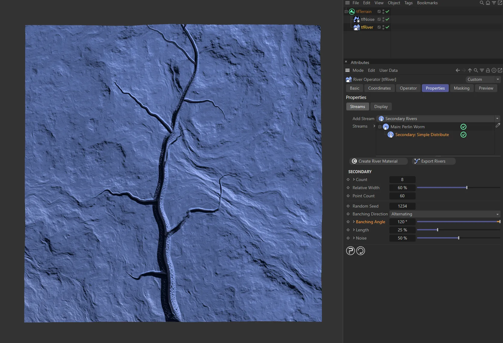
The Branching Angle is now 120 degrees, in this image.
Unfold the drop-down arrow to reveal another parameter.
Variation
Section titled “Variation”Applies randomness to each secondary river’s branching angle.
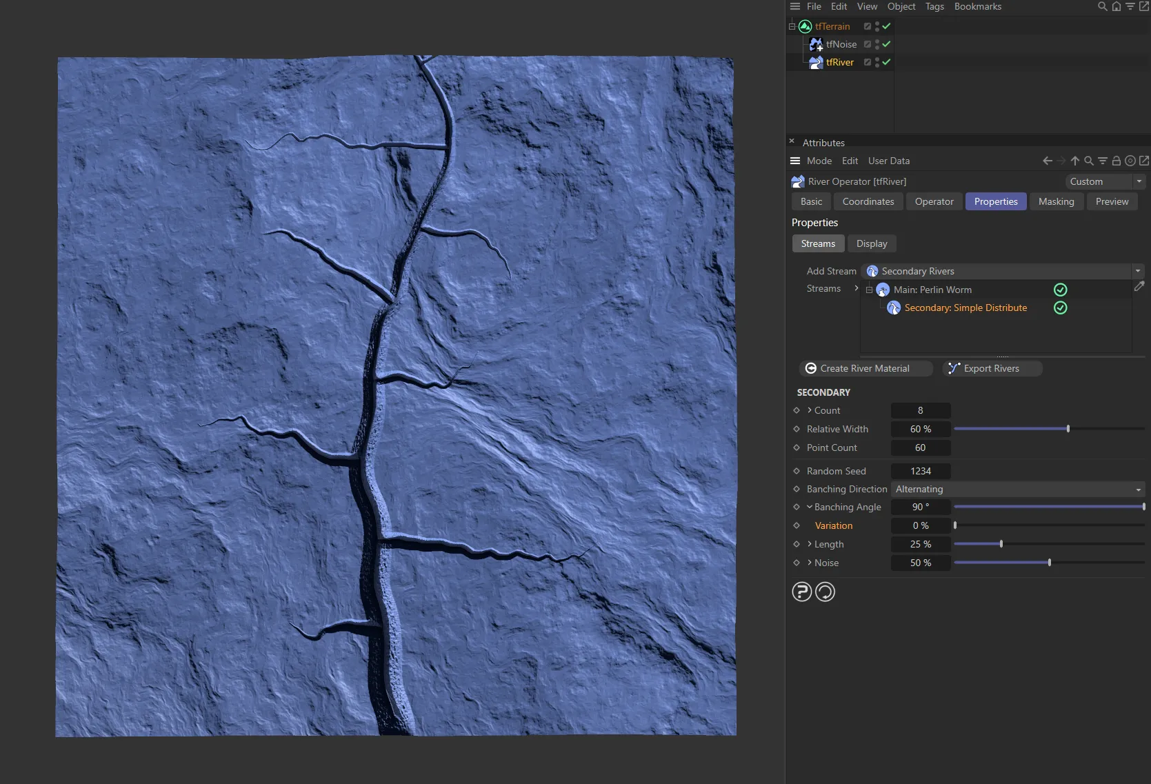
There is no variation to the Branching Angle settings, in this image.
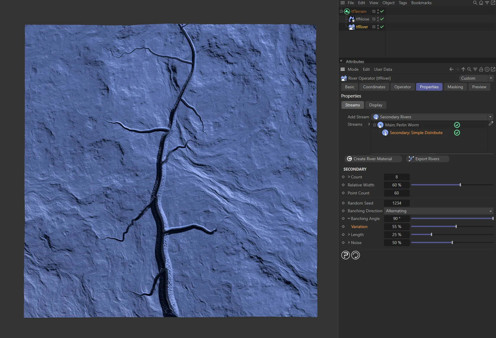
Here, the Variation is 55%, giving a more natural, organic look.
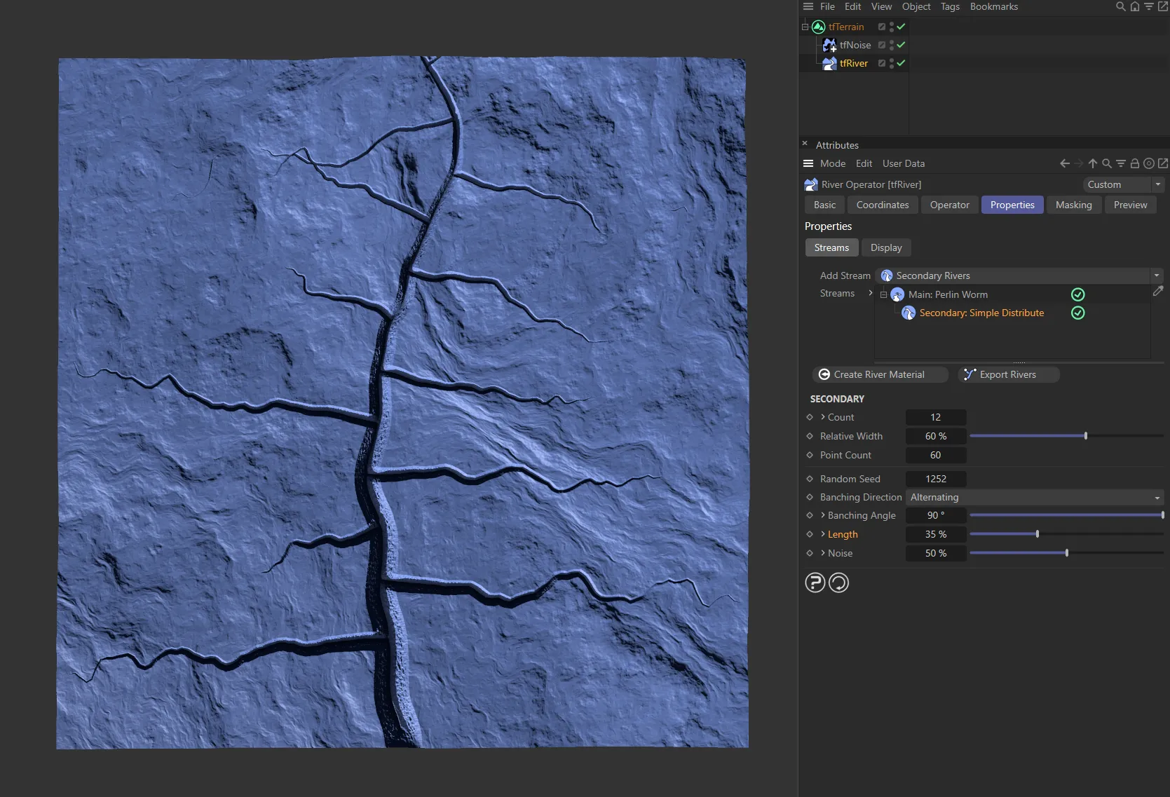
Length
Section titled “Length”Controls the length of the secondary rivers.
Unfold to reveal two other parameters.
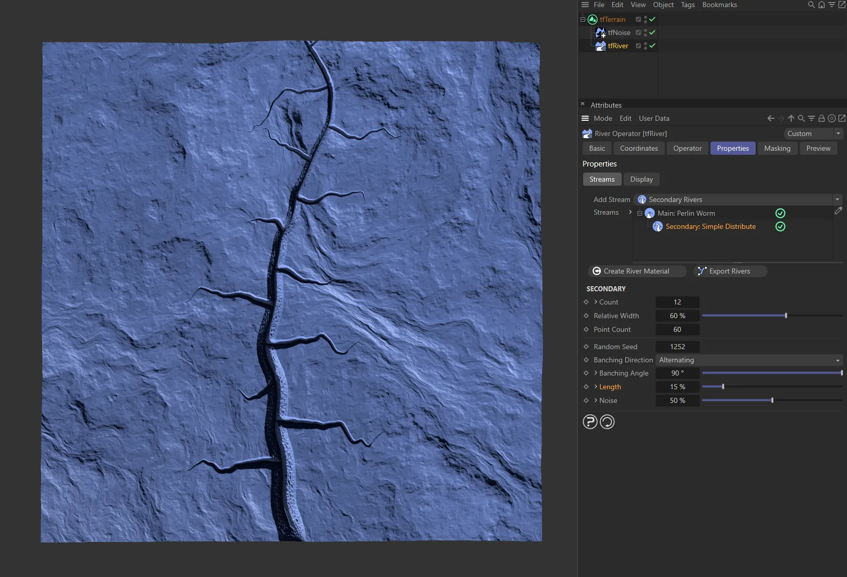
A Length setting of 15%.
With the Length setting raised to 35%.
Variation
Section titled “Variation”Applies randomness to each secondary river’s length.
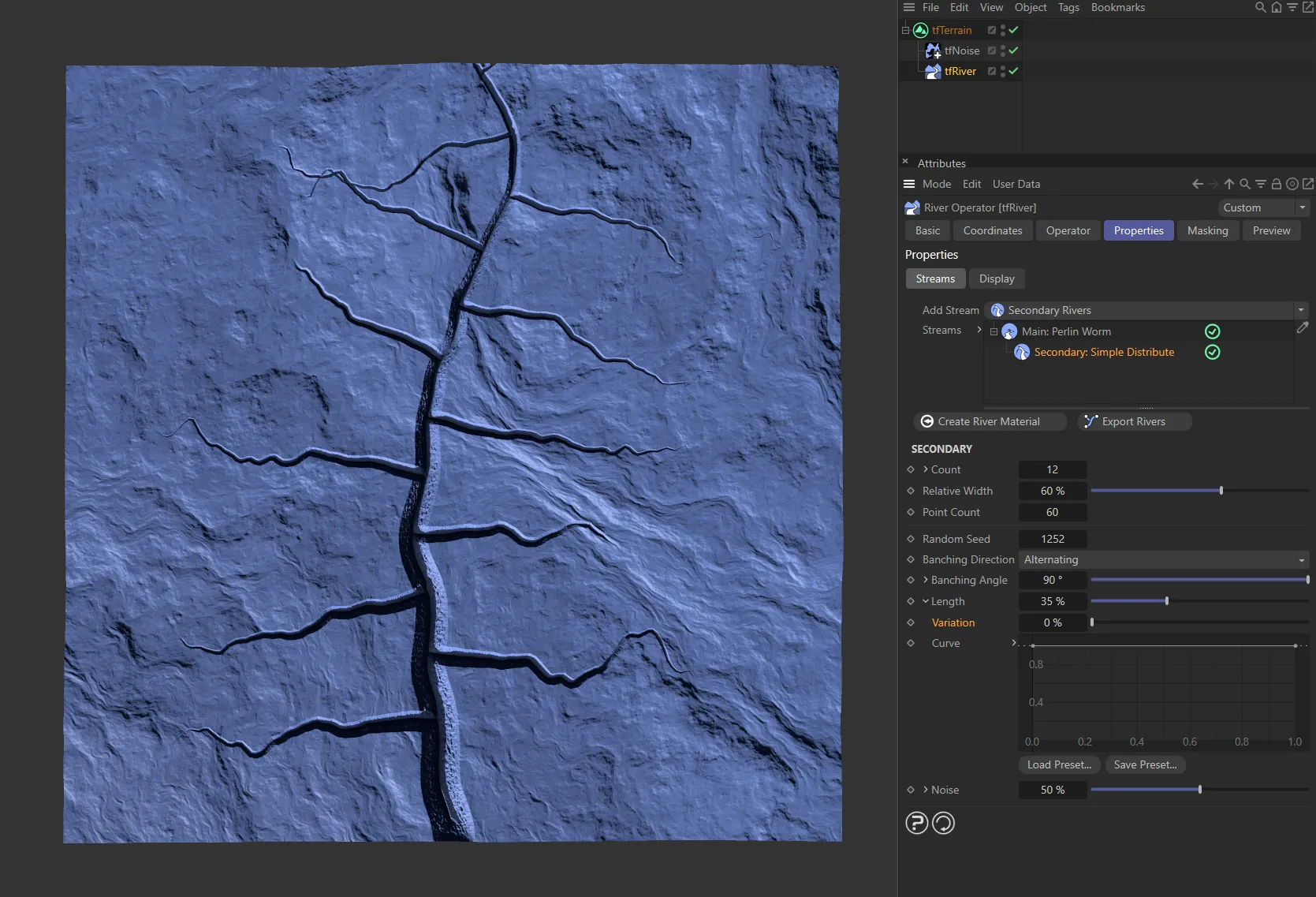
There is no variation to the Length settings here.
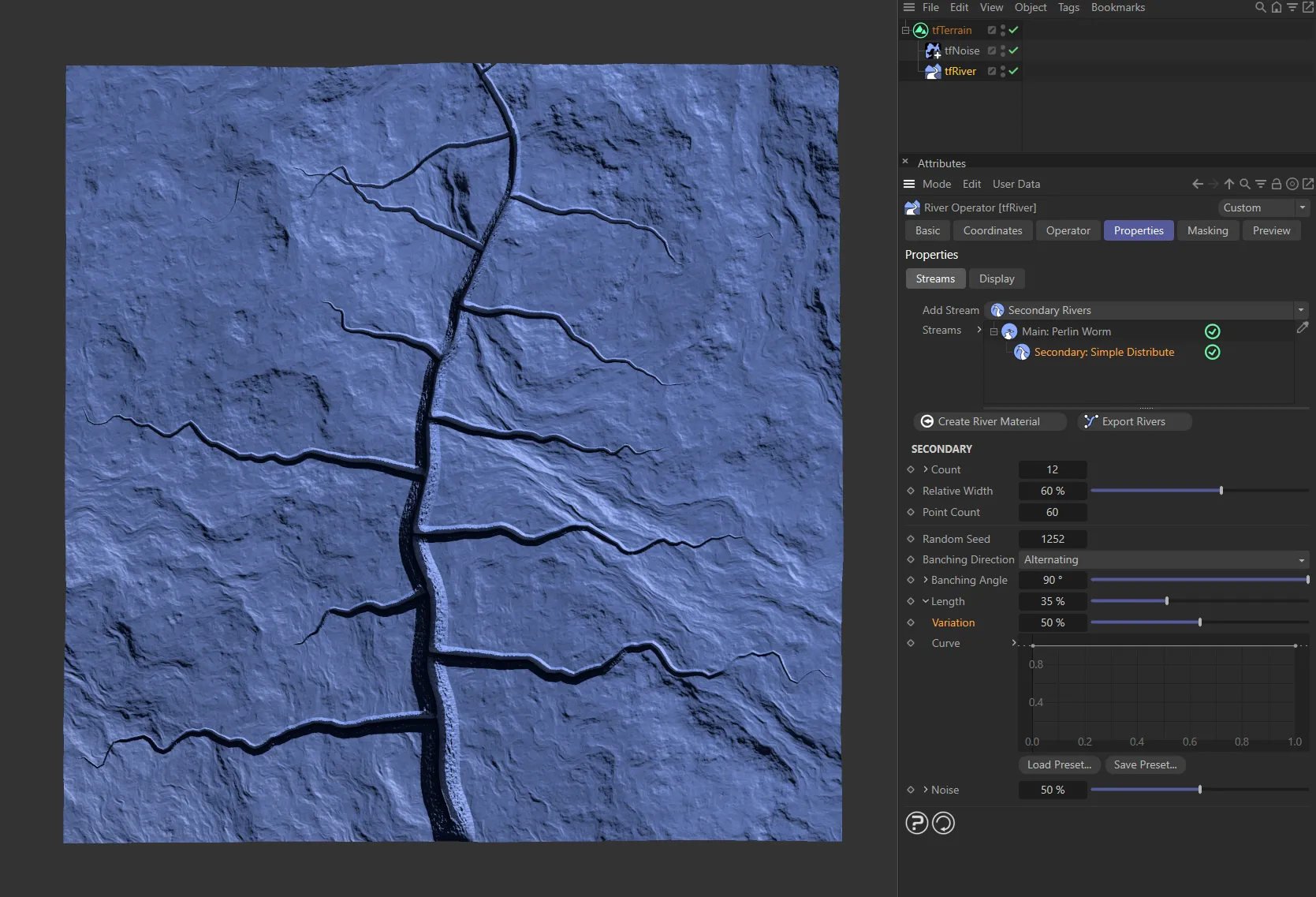
In this image, a Variation of 50% gives a more organic look to the lengths of the secondary streams.
Controls the secondary river’s length, based on their branching position along the parent river.
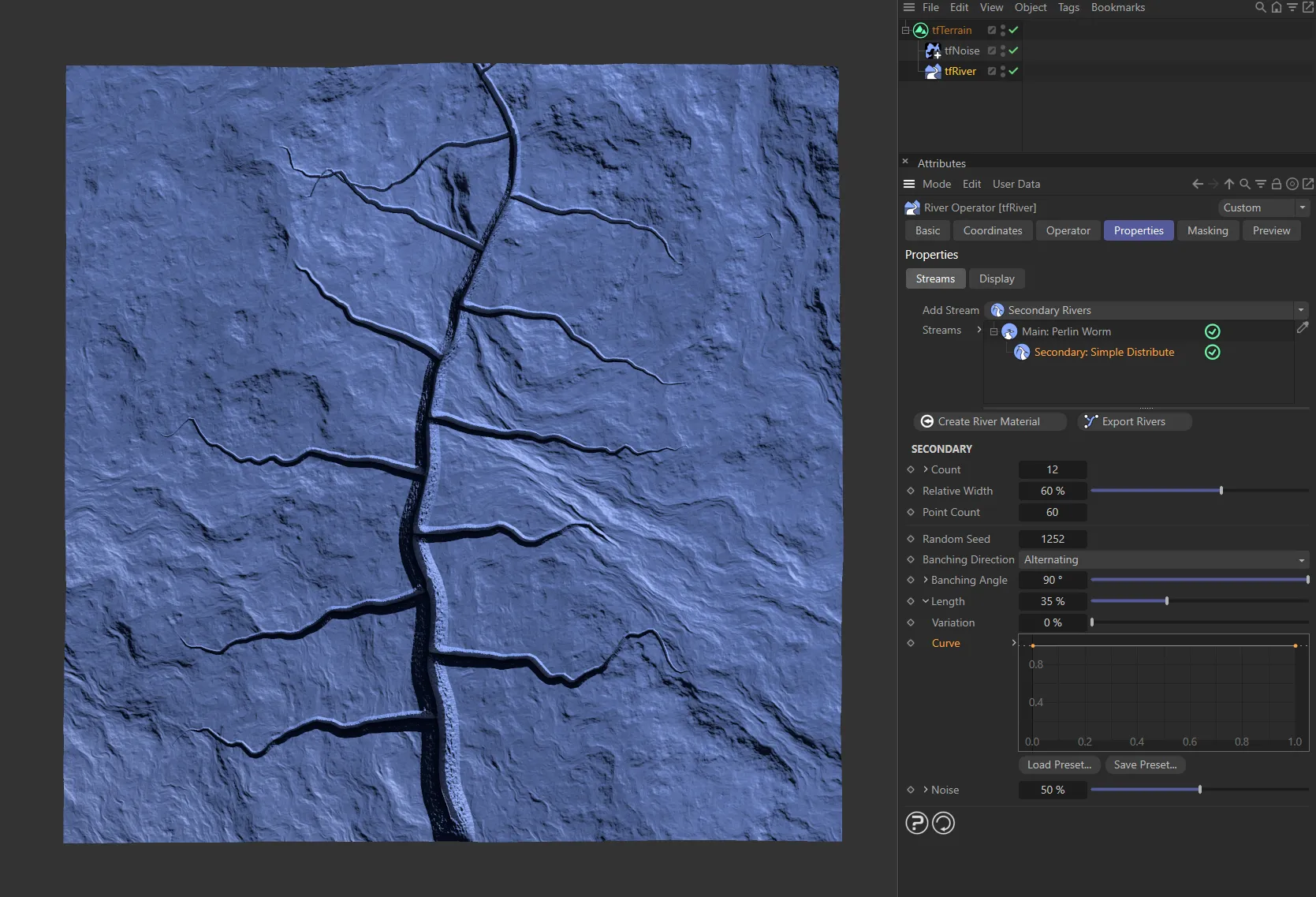
A full strength spline is driving this Curve setting.
This Curve is driven by the linear spline.
Controls the effect of a noise on the secondary rivers’ paths.
Unfold the drop-down arrow to reveal another parameter.

A Noise value of 25%.

The Noise is raised to 90%, here.
Scales the noise.
Larger values will make the secondary rivers wind more smoothly.
The Scale setting is 20%, in this image.

It has been raised to 50% here, smoothing out the wind of the secondary rivers.
Deform tab
Section titled “Deform tab”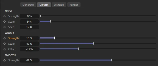
Deform tab menu settings.
Moves the river points according to a Noise field.
Strength
Section titled “Strength”The intensity of the noise effect.
There is 0 (zero) % Strength to the noise, in this image.
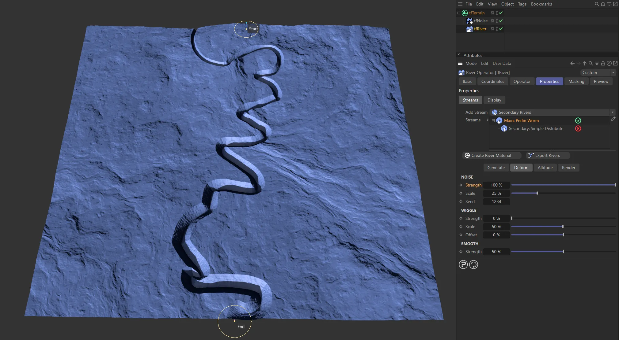
A noise Strength value of 100%.
Scales the noise field.
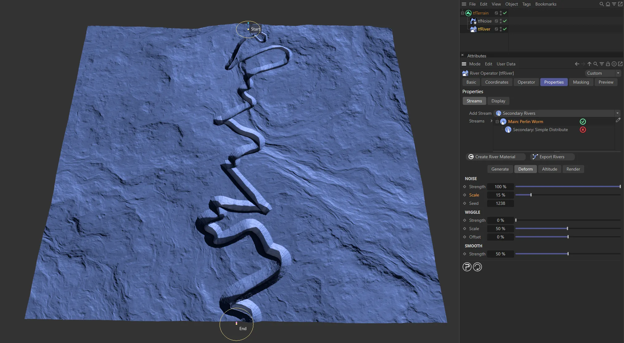
The Scale of the noise set at 15%.
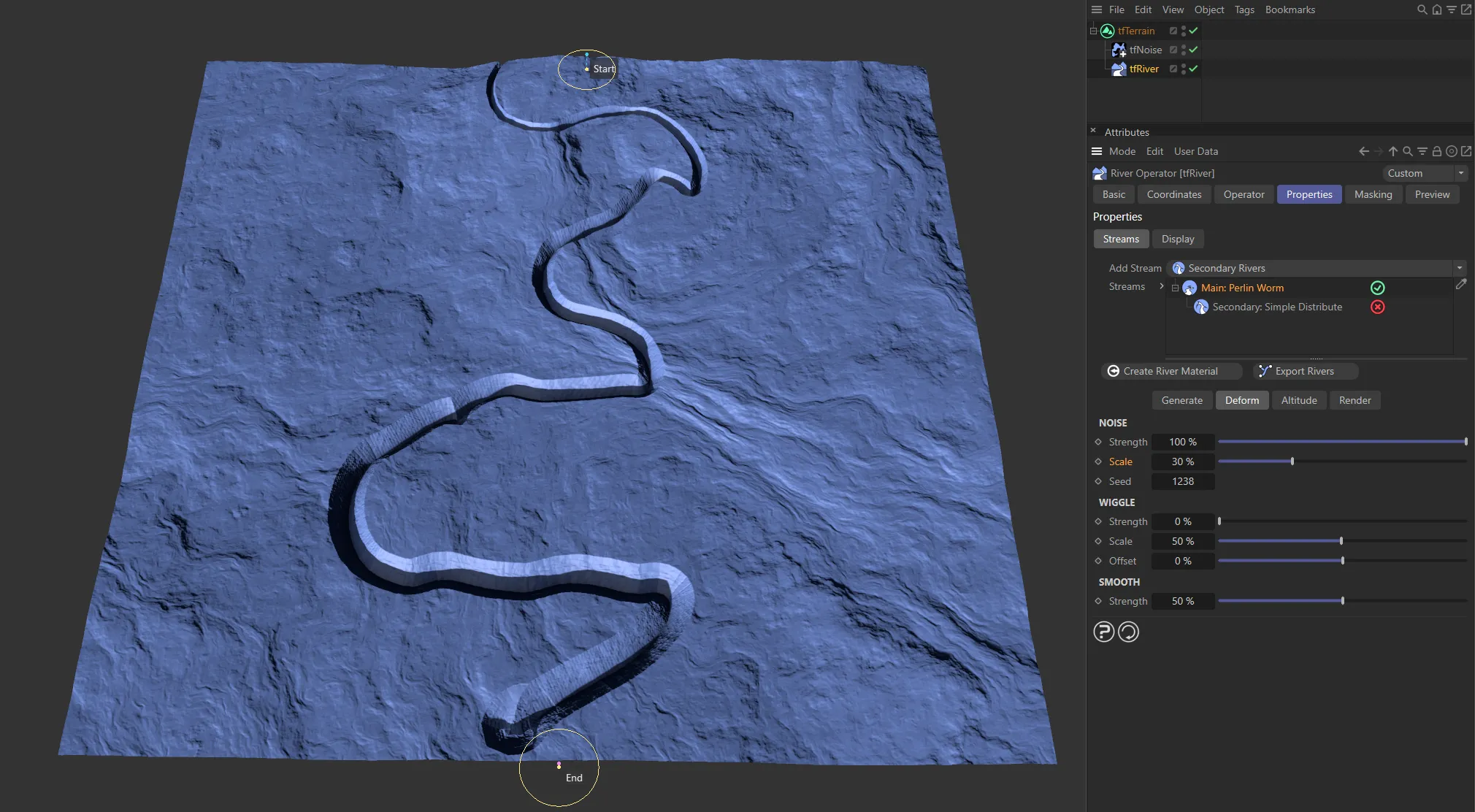
Doubled to 30%, in this image.
Random start value.
Each different value gives a totally different result.
Wiggle
Section titled “Wiggle”Moves the river points away from the path using a sine function.
Strength
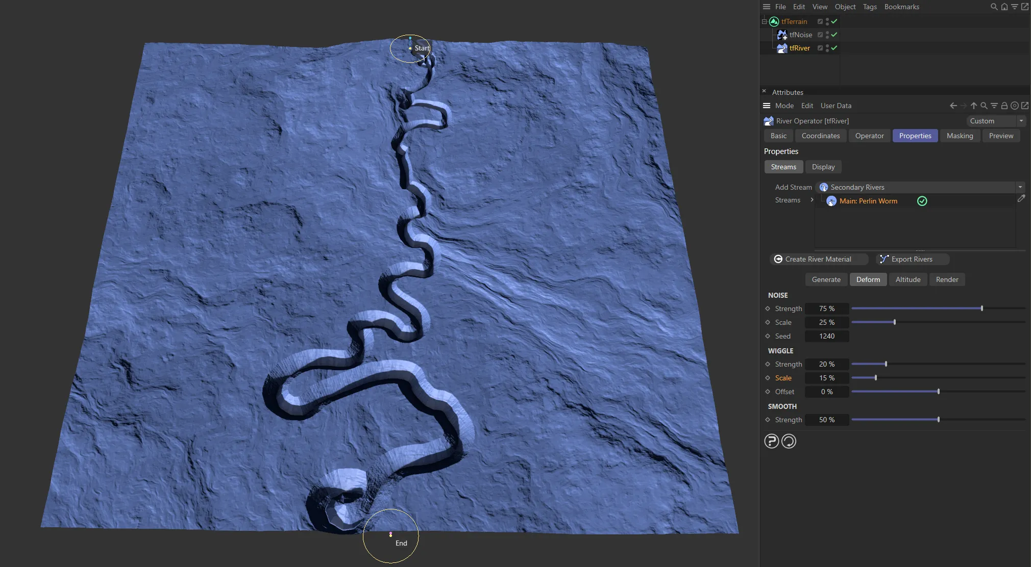
Section titled “Strength”The intensity of the wiggle effect.

Here, there is no wiggle Strength set.

Strength raised to 20%, giving a wiggle effect.
Scales the sine curve.
Wiggle Scale setting of 15%.

Increased to 42%, in this image.
Offset
Section titled “Offset”Moves the sine along the river path.
Smooth
Section titled “Smooth”Strength
Section titled “Strength”Increase this to filter out sharp bends from the river path.
Altitude tab
Section titled “Altitude tab”Each main river node has this group of parameters.
They control how the altitude of the river path points is computed, after the river path (which is only 2D) has been generated.
The user can choose between different modes of applying altitude to the river points.
Set as Downhill Flow, by default.
The alternatives are: None and Project on Terrain.
The original altitude of the points is retained.
Useful for rivers in rather flat landscapes, if they don’t need to flow down mountains in an obvious manner.
Project on Terrain
Section titled “Project on Terrain”This will simply inherit the altitude from the underlying terrain.
Less suitable for realistic rivers, but can be useful to create paths and walkways.
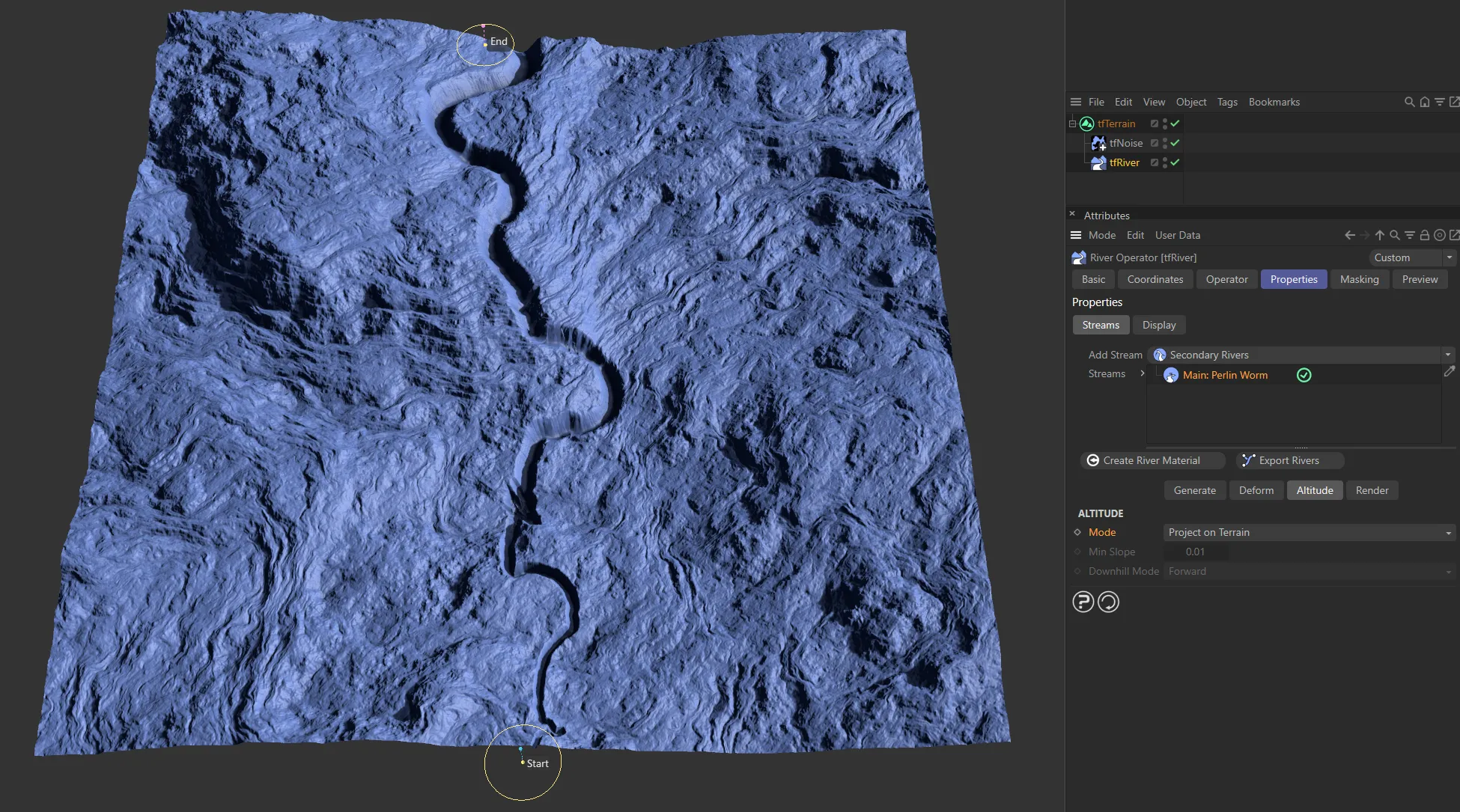
With a Mode of Project on Terrain, the altitude is inherited from the underlying terrain.
Downhill Flow
Section titled “Downhill Flow”The most realistic way of calculating the altitude of river points, is to allow a downhill path only.
If the terrain under the river is going downhill along the river flow direction, the river will follow the terrain slope.
However, if the terrain goes uphill, the river will keep a steady decline, thus cutting into the ground.
There are two additional parameters available for this mode.
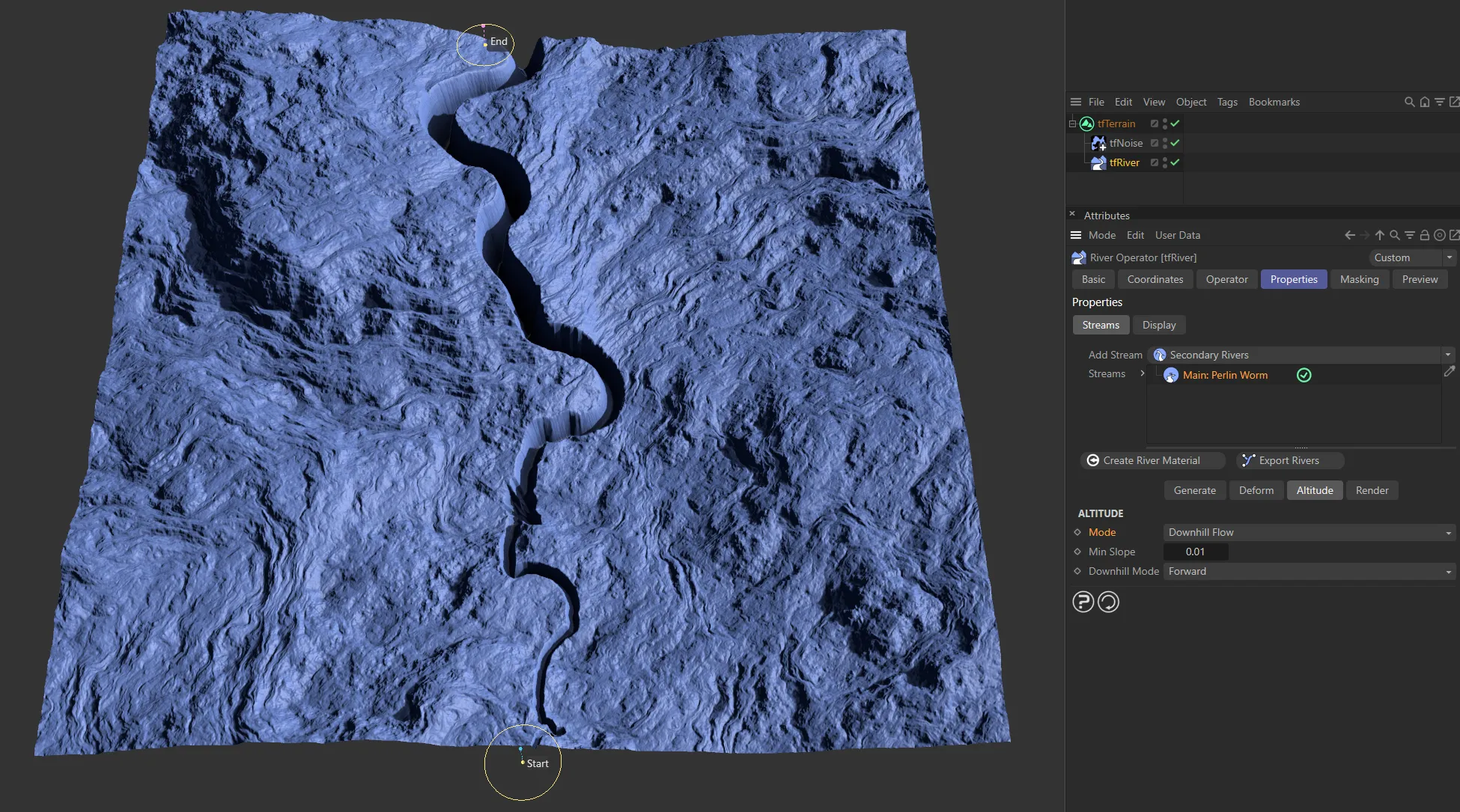
The Mode is Downhill Flow, here, with the river altitude following the terrain slope.
Min Slope
Section titled “Min Slope”Each successive river point will by moved downwards by at least this distance.
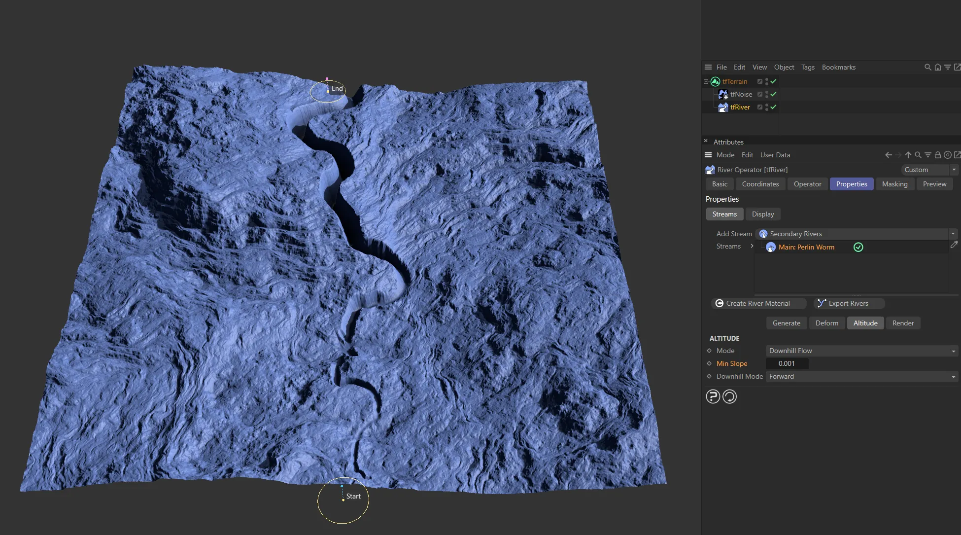
A Min Slope setting of 0.001 gives little change.
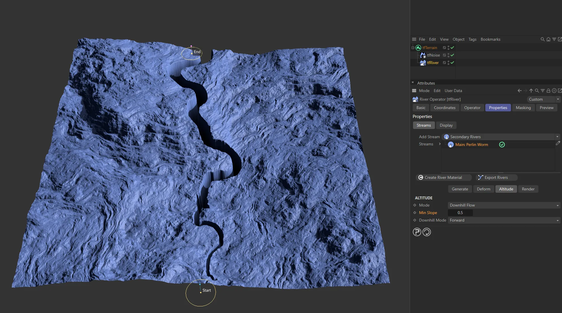
Increased to 0.5, there is a definite difference in altitude.
Downhill Mode
Section titled “Downhill Mode”Set as Auto, by default.
The other options are: Forward and Reverse.
The river flows downhill from its start or end point, depending on which is higher.
Forward
Section titled “Forward”The river flows downhill from its start point.

A Downhill Mode setting of Forward.
Reverse
Section titled “Reverse”The river flows downhill, in reverse, from its end point.
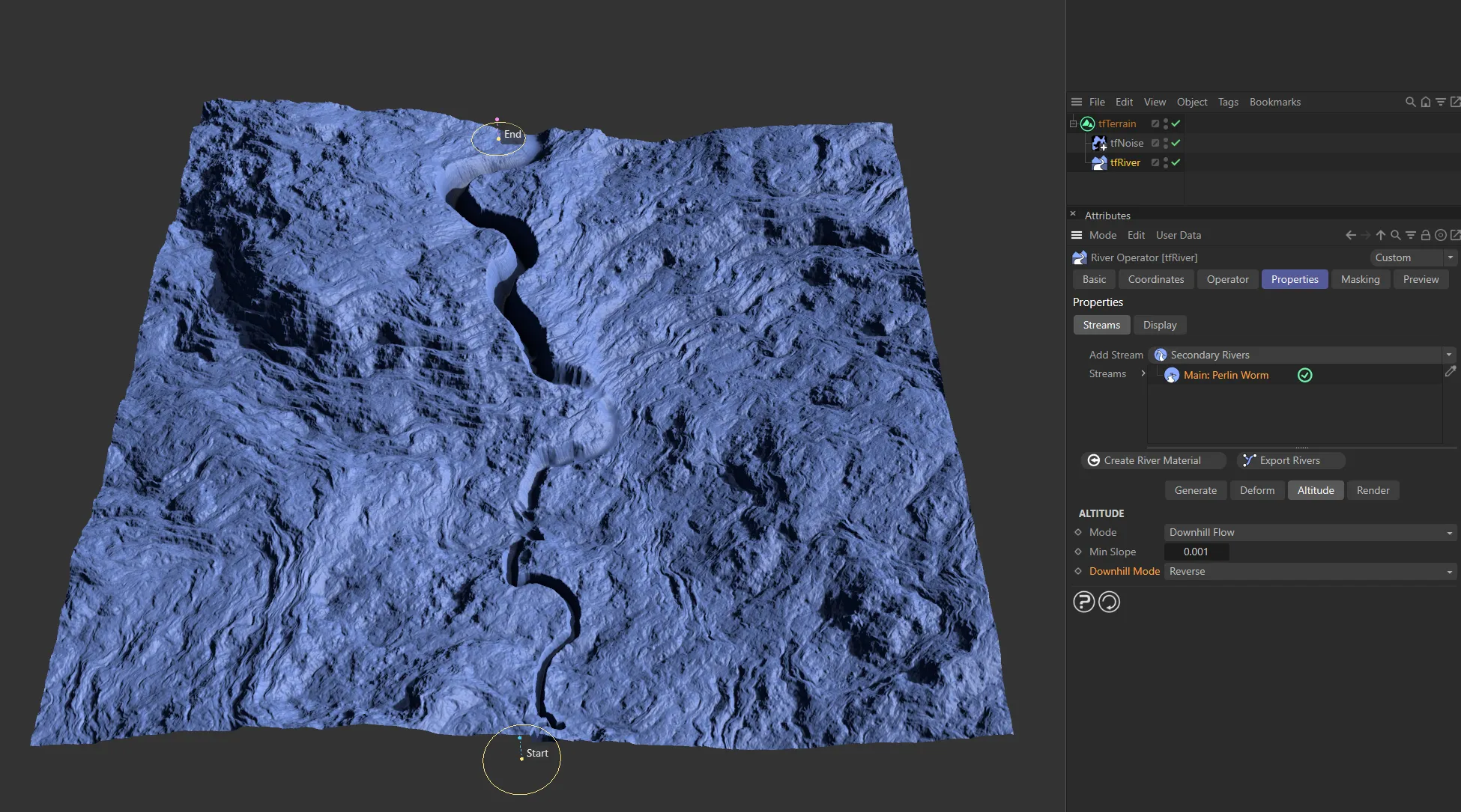
Here, the Downhill Mode is Reverse.
Render tab
Section titled “Render tab”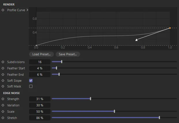
Render tab menu settings.
To bring river path data to the terrain grid, a custom 2D rasterizer was developed.
This allows rendering the river data with precise altitude information and can even render UV-mapped structures along the paths.
During rasterizing, tfRiver renders multiple passes of the river data into separate maps and then composites them together, to form the final output terrain.
Most of these passes are available as custom output maps.
This stage also defines the profile of the river bed, which can be defined using a custom spline curve.
There are several other parameters to tweak the rendering stage with.
Render
Section titled “Render”How river paths and altitude data are rendered to the terrain grid.
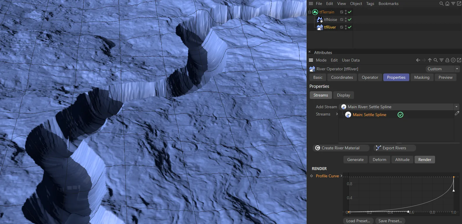
Profile Curve
Section titled “Profile Curve”This curve defines the cross-sectional profile of the river bed.
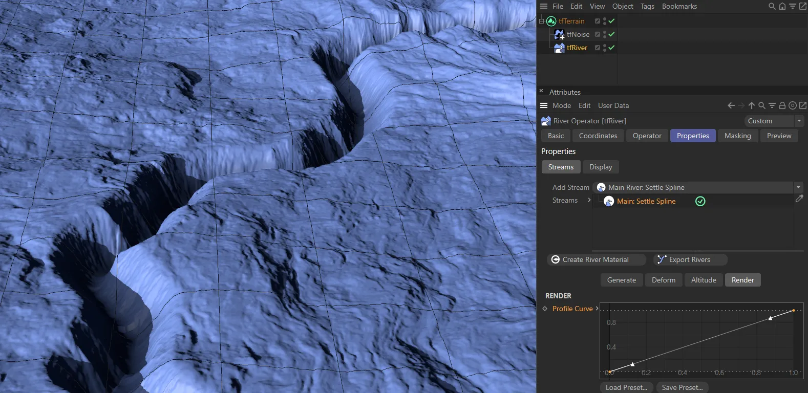
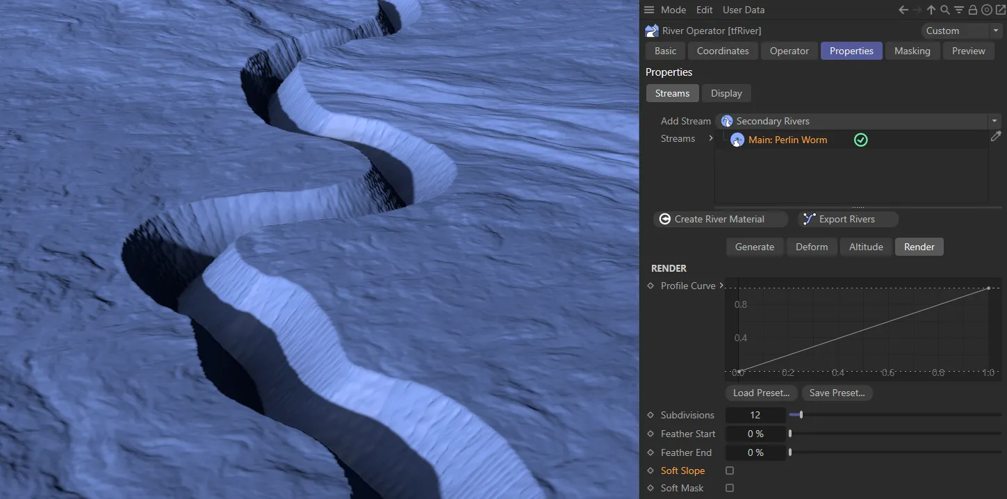
The default, linear profile.
This is a user created profile, causing steep drops from the edge to the river bed.
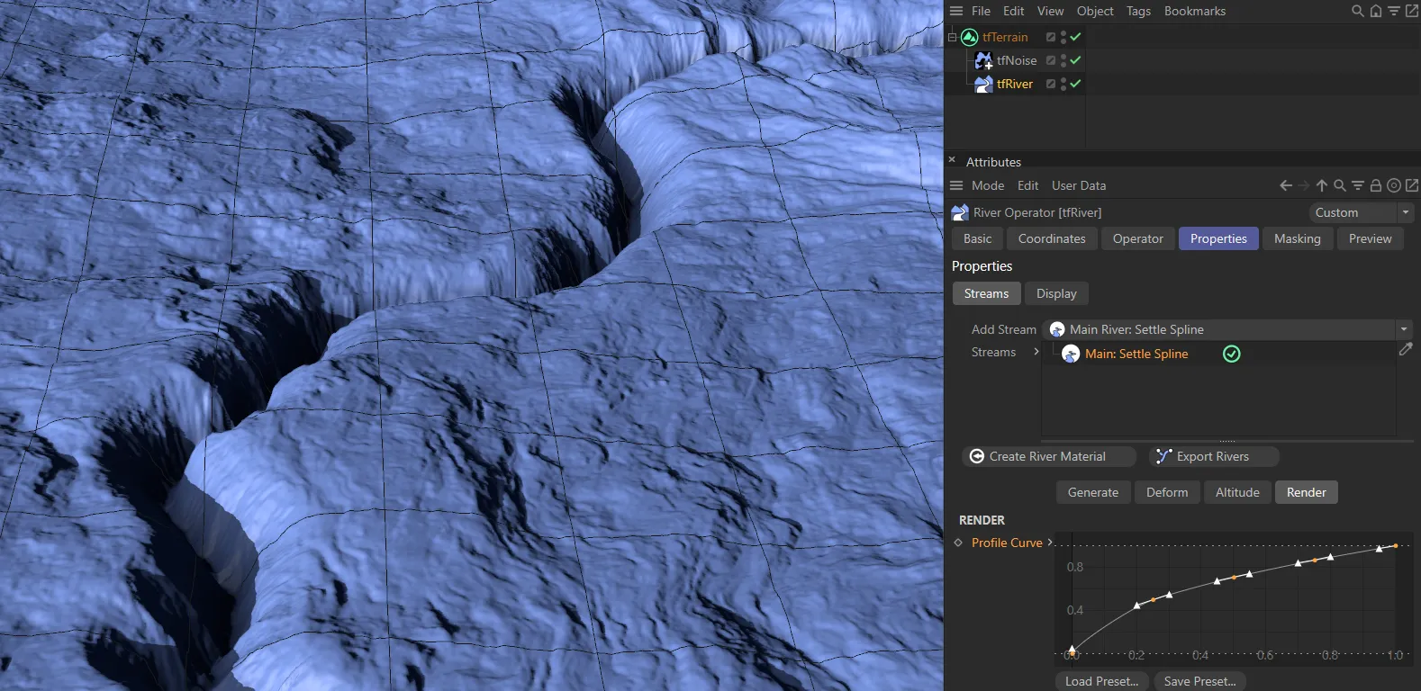
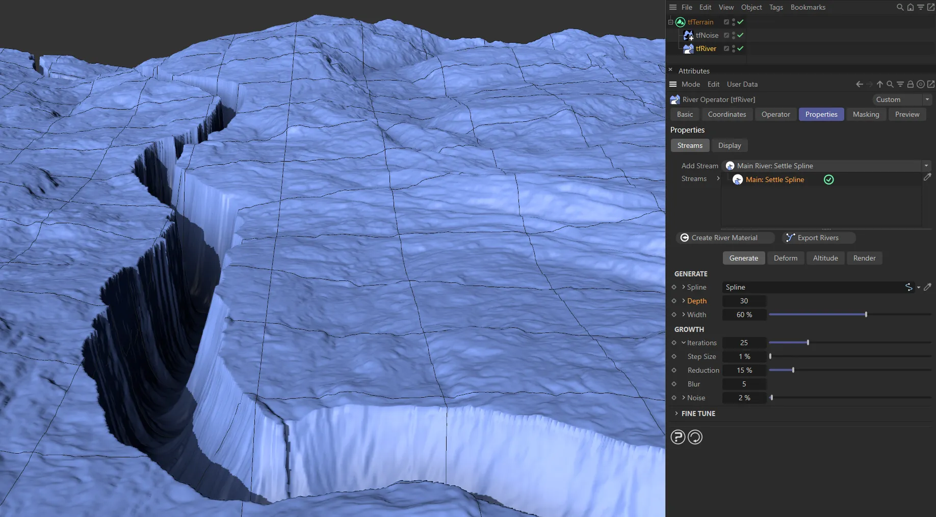
The root spline preset here results in a crevasse.
Subdivisions
Section titled “Subdivisions”If you experience artefacts in the rasterized river, increase this to subdivide the rasterizer geometry.
Keep as low as possible but as high as necessary.
Feather Start
Section titled “Feather Start”Feathers the start of the river; increase for a softer river start.
Feather End
Section titled “Feather End”Feathers the end of the river; increase for a softer river end.
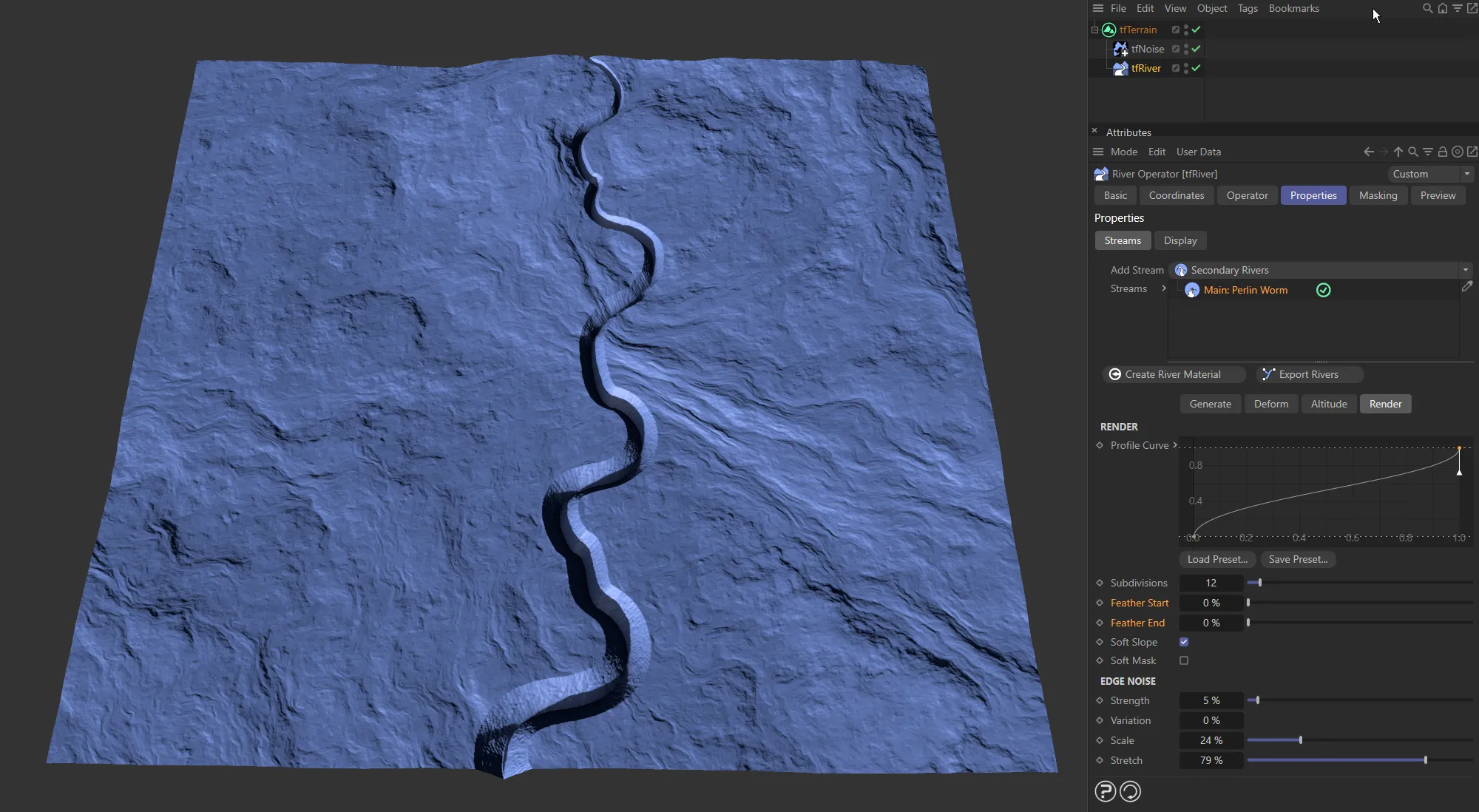
No Feather Start or Feather End value.
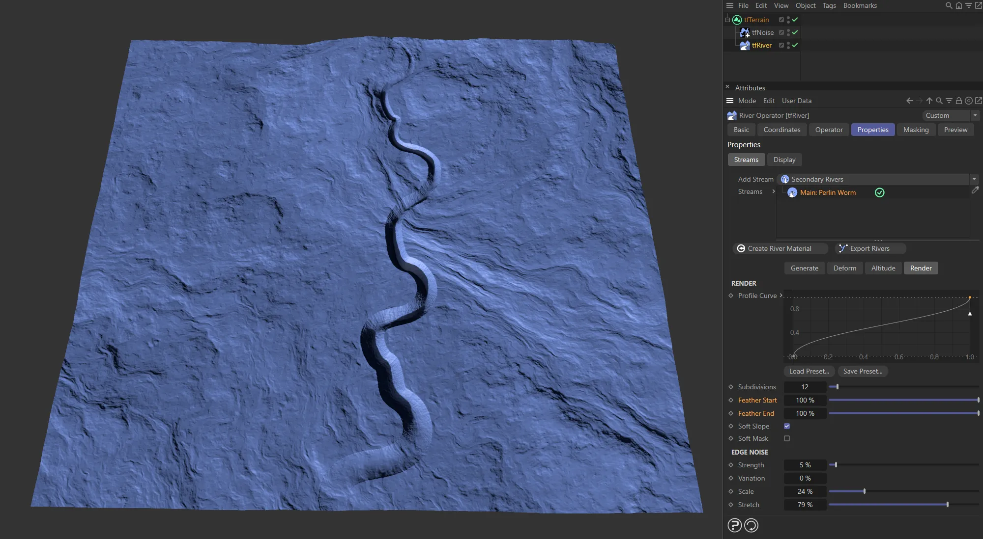
Here, the Feather Start and Feather End values are both 100%
Soft Slope
Section titled “Soft Slope”Softens the slope gradient of the river cutting into the terrain.
With Soft Slope disabled.
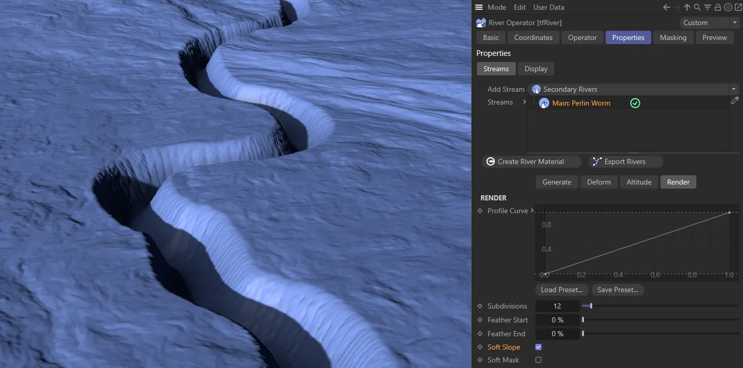
Soft Slope is enabled here, giving a softer look to the edge and gradient.
Soft Mask
Section titled “Soft Mask”Softens the rendered river mask.
Edge Noise
Section titled “Edge Noise”Noise can be applied to the river edges, to simulate the look of washed out canyons or eroded influx streams.
Strength
Section titled “Strength”Controls the intensity of the noise effect.
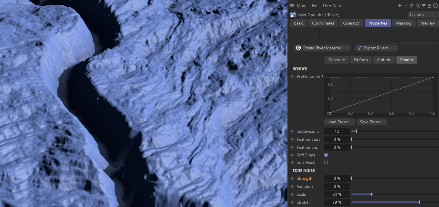
0 (zero) % Strength value to the edge noise.
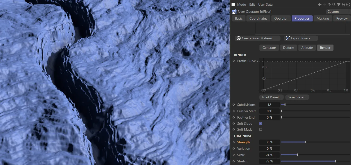
The Strength has been raised to 35%, in this image.
Variation
Section titled “Variation”Applies a variation to the Strength levels along the river path.
Scales the noise.
Stretch
Section titled “Stretch”Controls the ratio of noise stretching along river U and V.
Effectively, lower values give the look of washed out terraces, while greater values result in eroded influx streams.
Custom Output Maps
Section titled “Custom Output Maps”tfRiver, like many other operators, offers custom output maps for use in the Terrain Operator Shader.
There are dedicated outputs for river altitude, river mask, and relative river slope, all in the Preview tab.
Using the latter, the user can e.g. create rapids and waterfalls on steeper slopes.
A by-product of the altitude calculations is the River Slope map, which encodes the normalized slope of all river points; areas with brighter points would be good locations for rapids or waterfalls.
Copyright © 2026 INSYDIUM LTD. All rights reserved.