tfTerrain
The tfTerrain object is the starting point in creating a custom landscape; it should always be the parent object within a TerraformFX object hierarchy.
It evaluates operator objects, placed as its children, and generates terrain features as a result.
By default, a new tfTerrain object will automatically include four operators as its children: tfNoise and tfGrid generators and both a tfFlood and a tfErosionHydraulic filter.
This set-up gives you a helpful starting point for your terrain.
However, these operators can be deleted in order to start from scratch.
There are separate pages explaining all of the operator parameters in full.
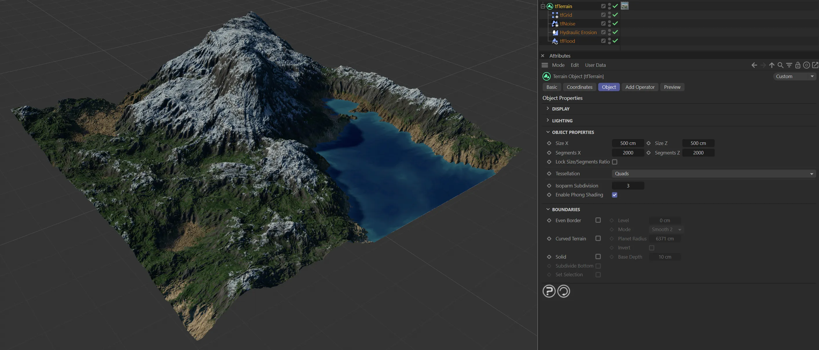
Start-up view for tfTerrain.
Object tab
Section titled “Object tab”Display
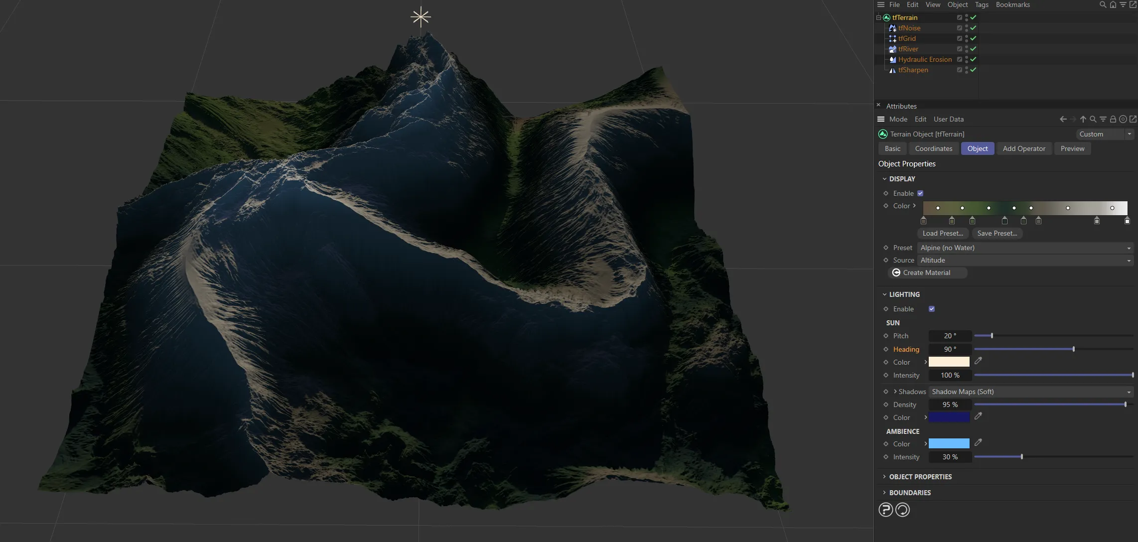
Section titled “Display”Enable
Section titled “Enable”This box is checked by default, giving the terrain color in the viewport.
This is determined by the gradient setting, which maps a gradient to either the Altitude or Slope values.
Unchecking it will disable the display mode making your terrain the default gray.
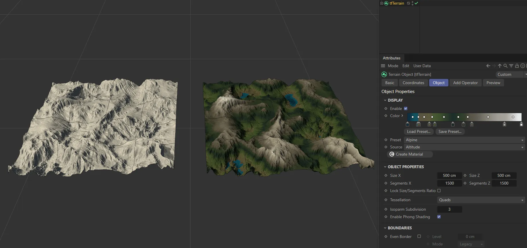
On the left-hand terrain, Display has been disabled. It is enabled on the right, with the color gradient applied.
There is a preset gradient in the viewport, which is applied, vertically, to the terrain.
The knots on the left-hand side are coloring the lowest points of the terrain and the knots on the right are coloring the highest points.
By clicking on these knots, you can change the colors.
The knots can also be dragged, to amend the gradient.
Load Preset
Section titled “Load Preset”There are various presets available to load in.
Save Preset
Section titled “Save Preset”You can save any custom presets that you have made and these will be available for the future in the Load Preset option, above.
Preset
Section titled “Preset”The default setting here is Alpine.
There are additional geographic set options: Alpine (no Water), Himalayas, Belitung, Grand Canyon, Grand Canyon (no Water), Atacama Desert, Tjorita and Nishinoshima.
It is also possible to select the analysis settings: Analysis, colored and Analysis, black and white.
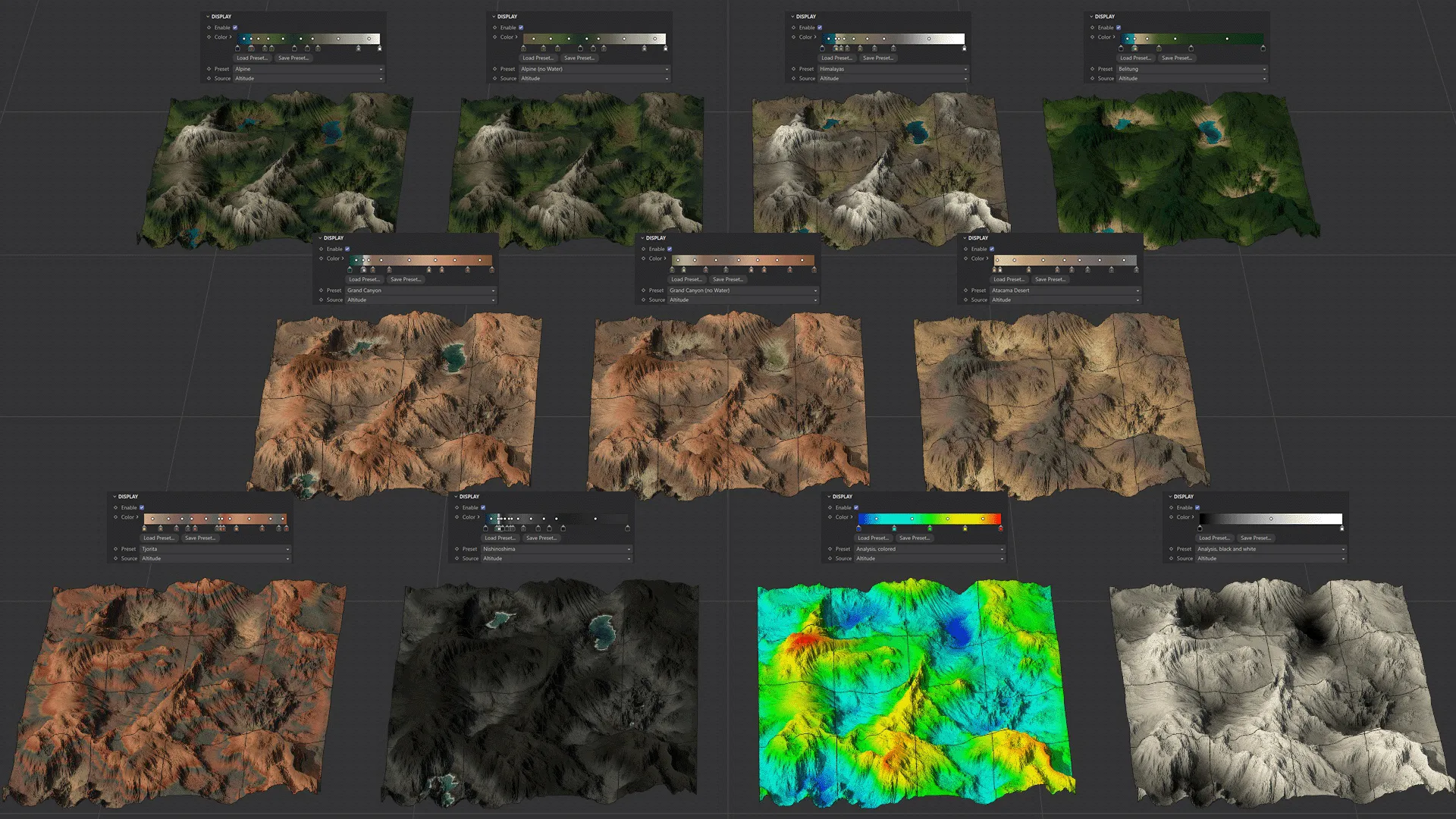
Image to show the eleven Preset terrain settings available.
Making a change to the Color settings on a Preset option will automatically change your Preset to ‘(Custom)’.
You can switch your Preset back to the original setting and your previous change will then be available as the (Custom) selection at the bottom of the options menu.
Finally, it is possible to select (Custom) as a starting option.
This will be, by default, identical in appearance to the Analysis, black and white setting.
Source
Section titled “Source”The source is set at the default of Altitude and can be changed to Slope.
Altitude gives the vertical application of the gradient, as mentioned.
Slope will apply the gradient based on the slope - how steep, or flat the areas in the terrain are.
The knots on the right-hand side of the gradient will now be coloring the steepest parts and the left will be coloring the flattest areas.
Create Material
Section titled “Create Material”Clicking this button will create a terrain material, which will automatically be applied to tfTerrain in the Objects Manager.
Lighting
Section titled “Lighting”Enabling this feature will internally create a tfLightRig, applying it to the terrain geometry.
Enable
Section titled “Enable”Tick this box to enable the tfLightRig.
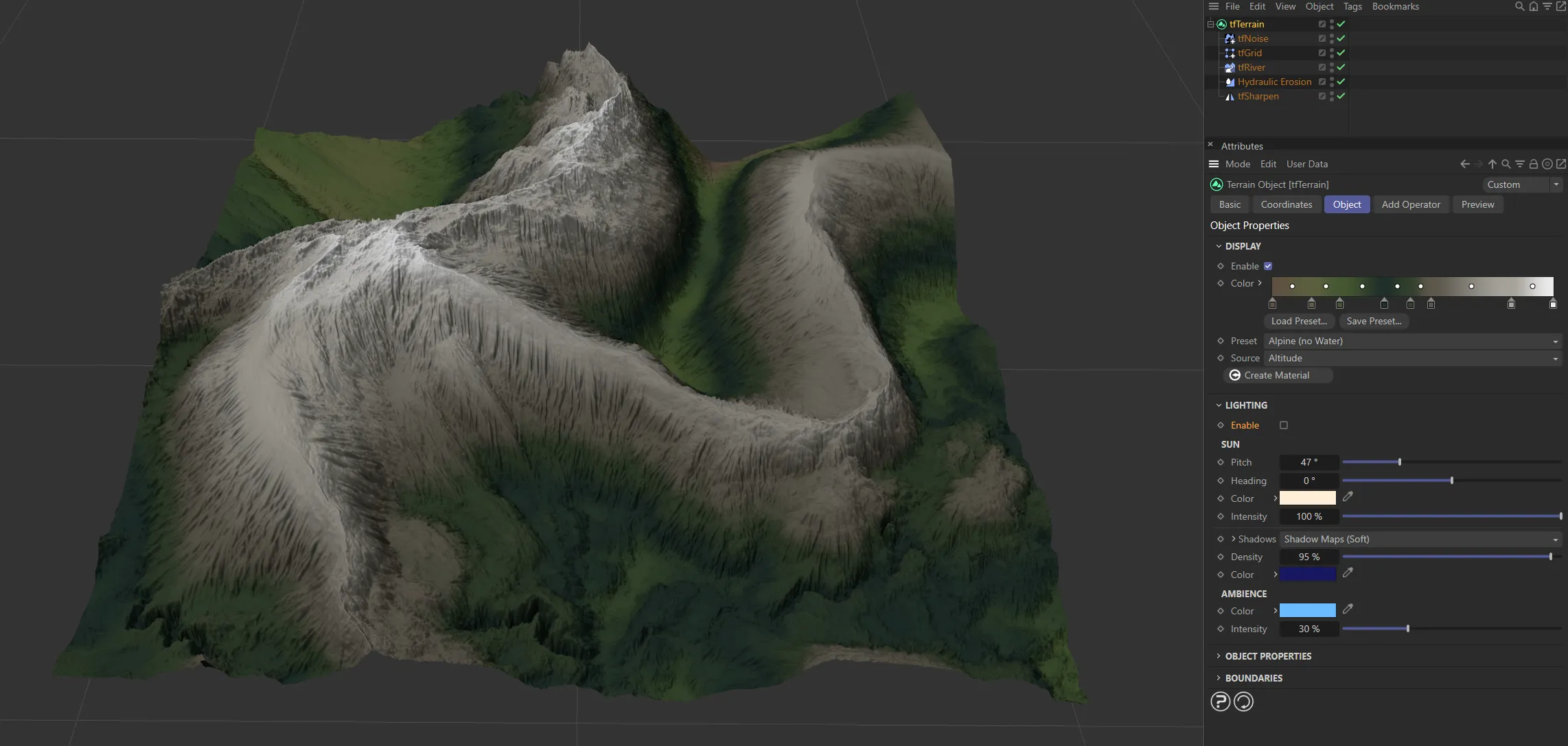
The lighting is disabled in this first image.
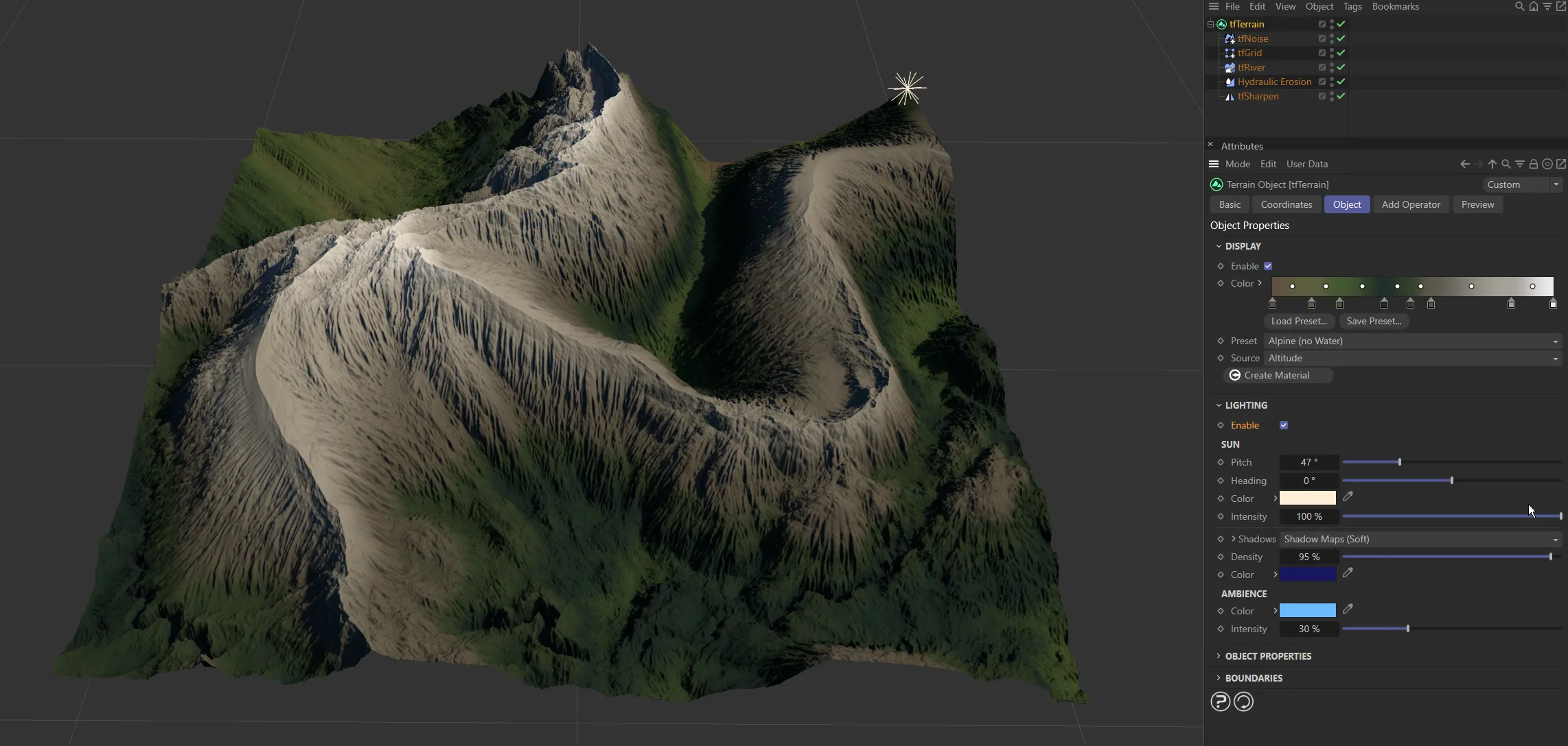
The lighting is enabled here.
Alters the pitch setting of the light.
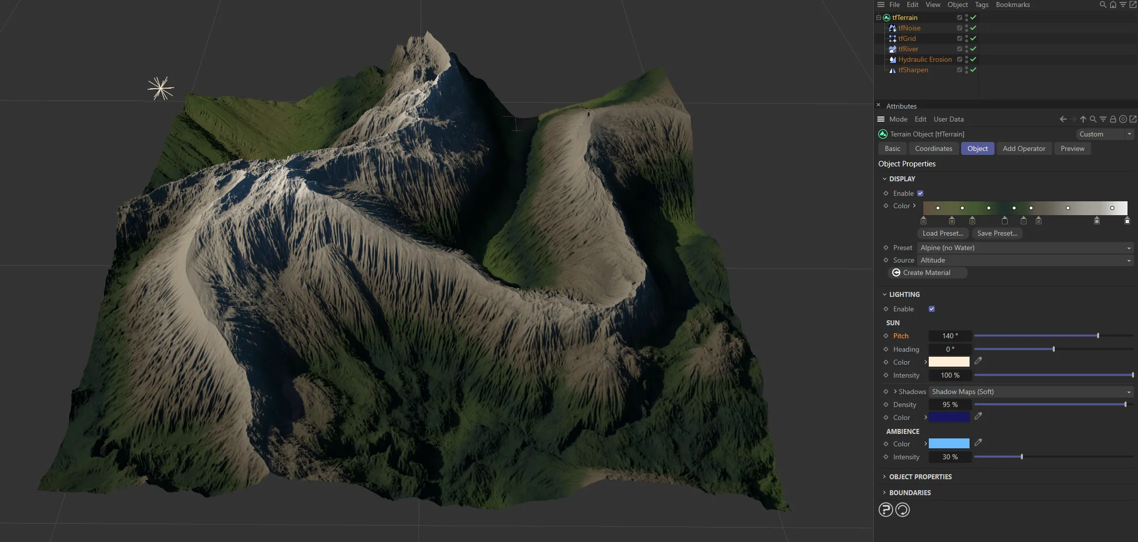
The ‘sun’ has a Pitch of 140 degrees here.

The Pitch value is 20 degrees, in this image.
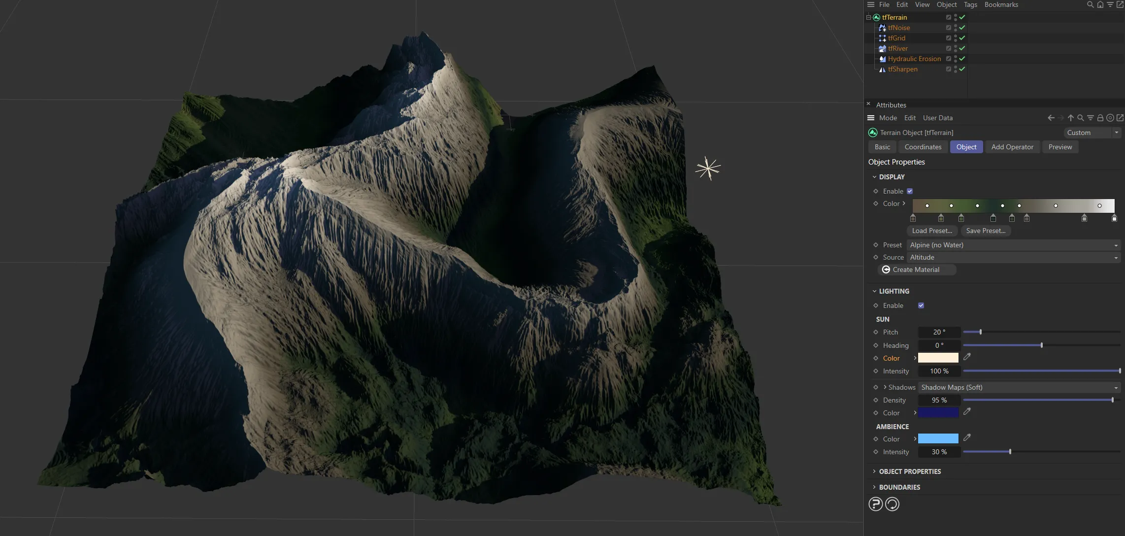
Heading
Section titled “Heading”Alters the heading setting of the light.
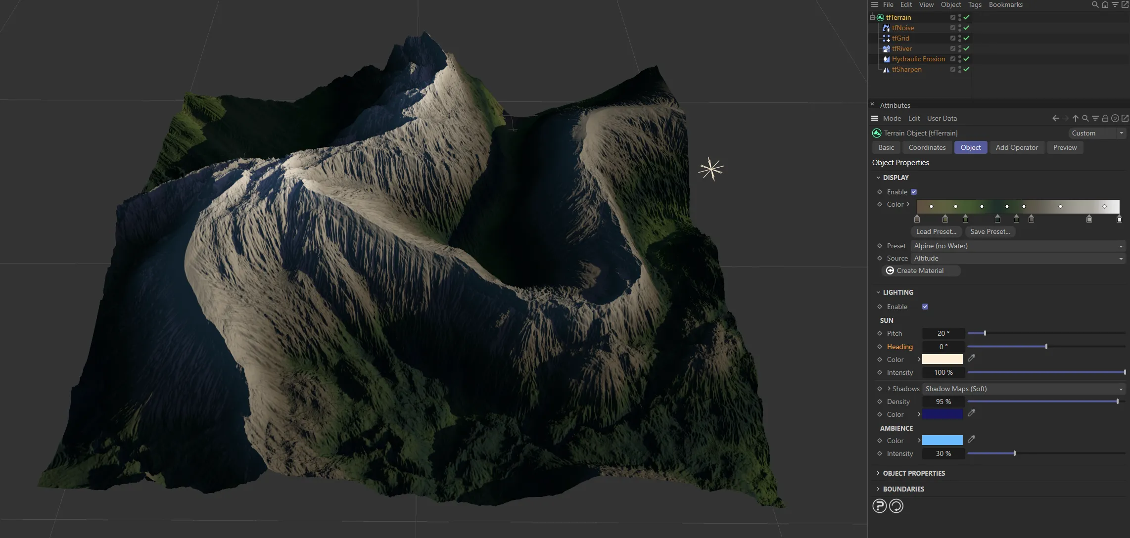
With the same Pitch of 20 degrees, the Heading remains at 0 (zero) degrees, as above.
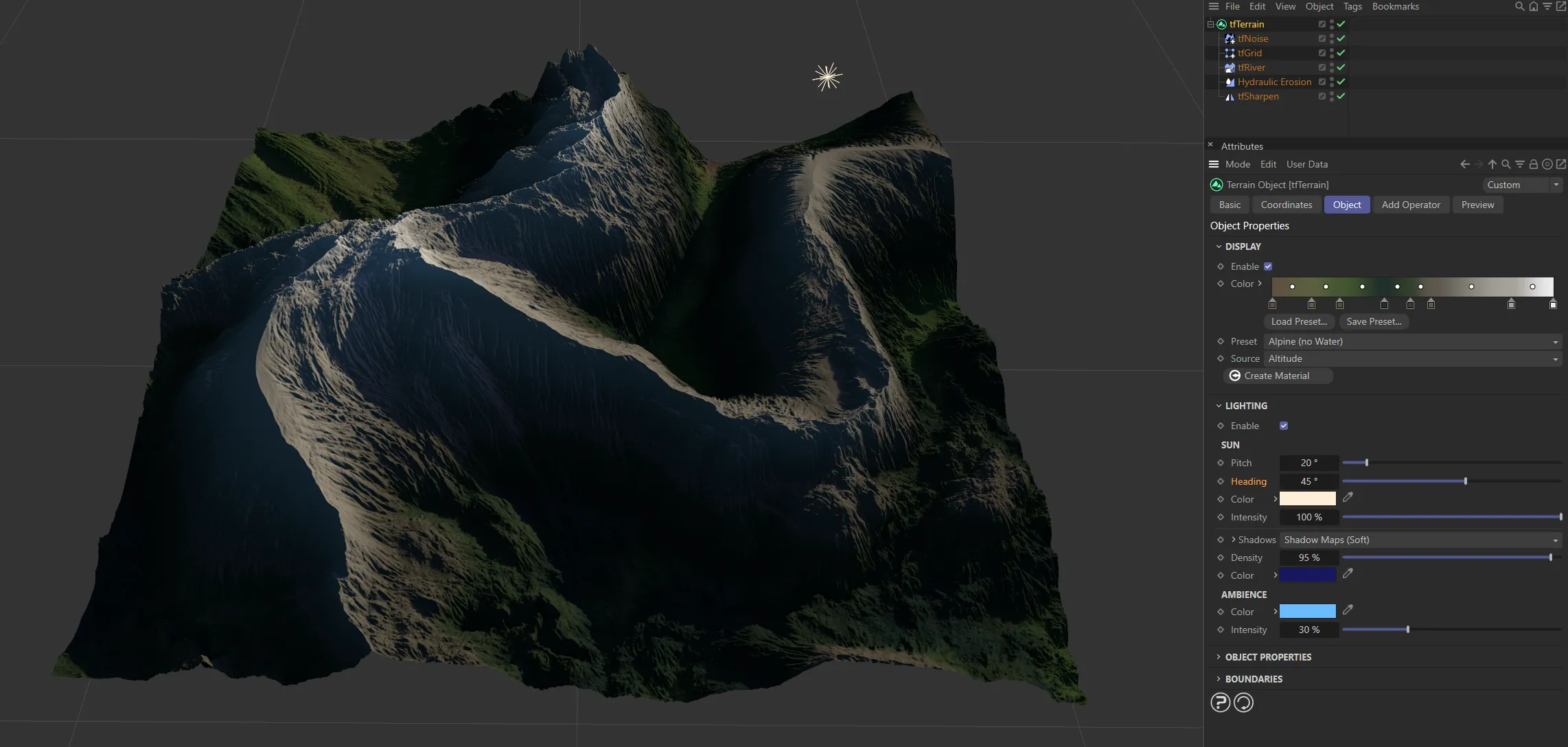
In this second image, the Heading is increased to 45 degrees.
And finally, here, the Heading is raised further, to 90 degrees.
The usual color settings are all available to customize your ‘sun’ lighting.
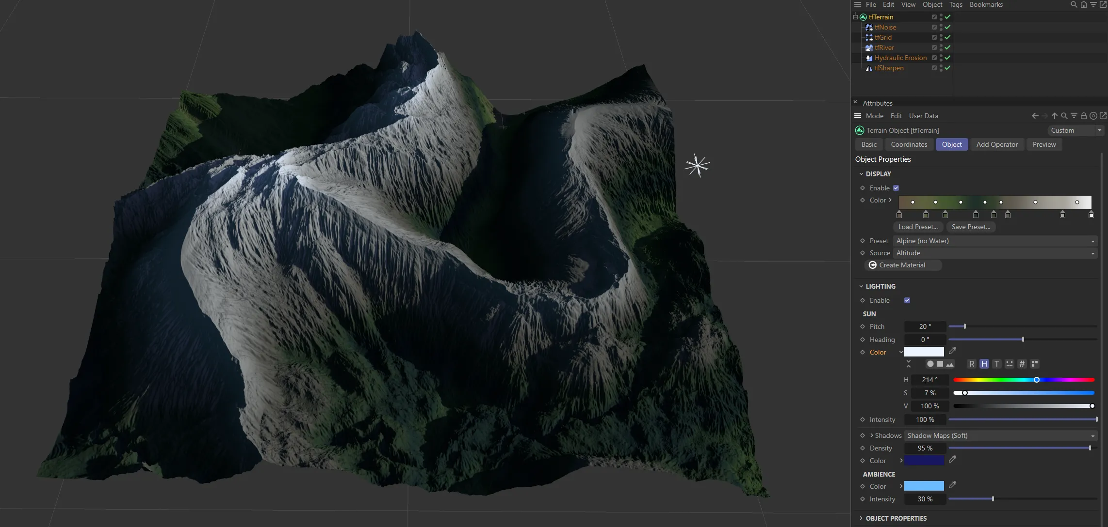
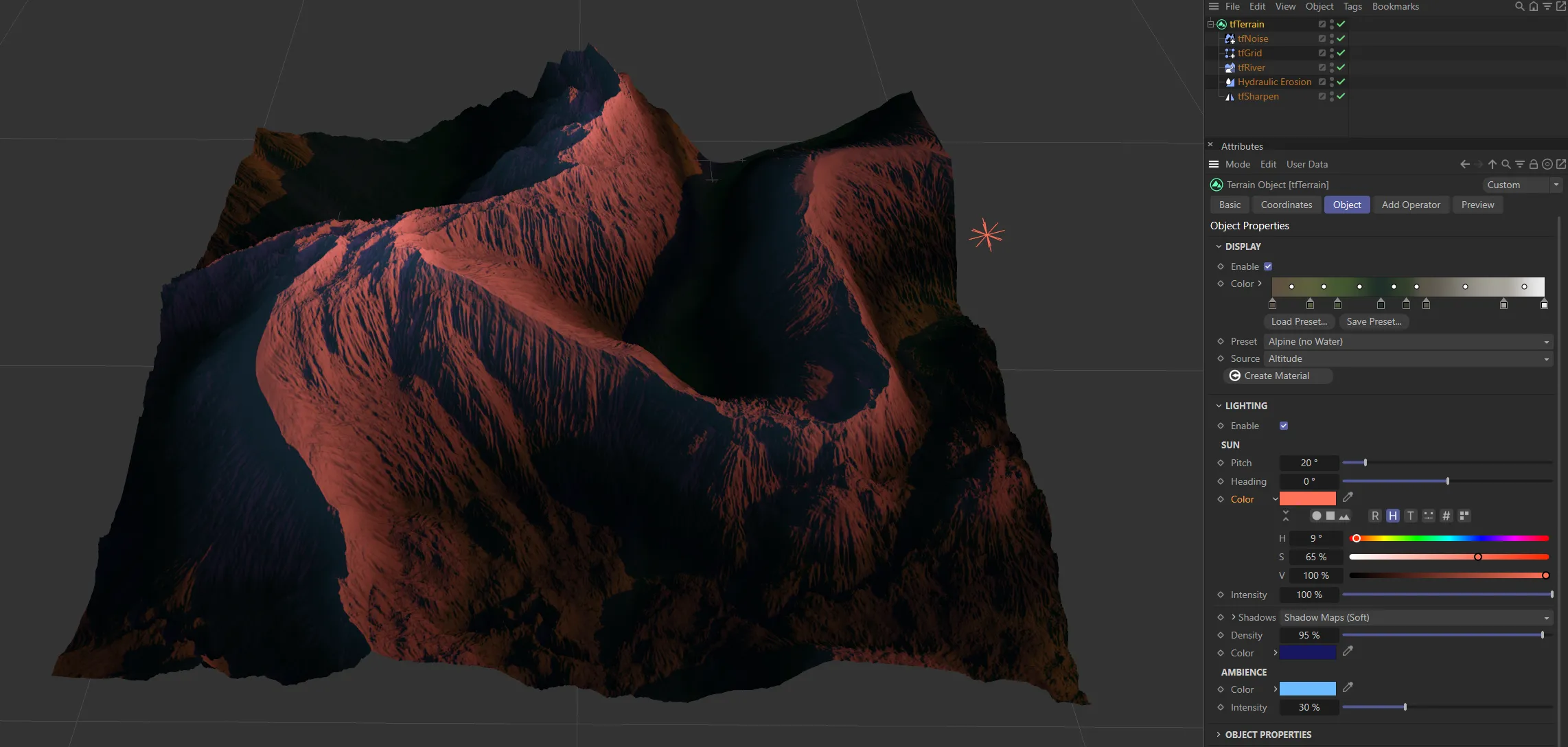
Three different Color settings are shown in these images.
Intensity
Section titled “Intensity”Use this setting to alter your Intensity level.
Shadows
Section titled “Shadows”Set as Shadow Maps (Soft), by default.
The alternatives are: None, Raytraced (Hard) or Area.
Density
Section titled “Density”Sets the shadow density levels.
As above.
Ambience
Section titled “Ambience”As above.
Intensity
Section titled “Intensity”You can alter the intensity of your ambience with this parameter.
Object Properties
Section titled “Object Properties”Size X
Section titled “Size X”Slide to increase or decrease the terrain in the X-axis.
Size Z
Section titled “Size Z”Slide to increase or decrease the terrain in the Z-axis.
Segments X, Segments Z
Section titled “Segments X, Segments Z”Increasing the number of segments will increase the quality of the definition of the terrain.
Lock Size/Segments Ratio
Section titled “Lock Size/Segments Ratio”Clicking this, to activate it, will mean that the ratio between the Size and Segments values will be locked, to maintain the quality, should you increase the sizes.
Tessellation
Section titled “Tessellation”By default, this is set to Quads - polygons with four edges, as below.
This can be changed to Triangles 1 or Triangles 2.
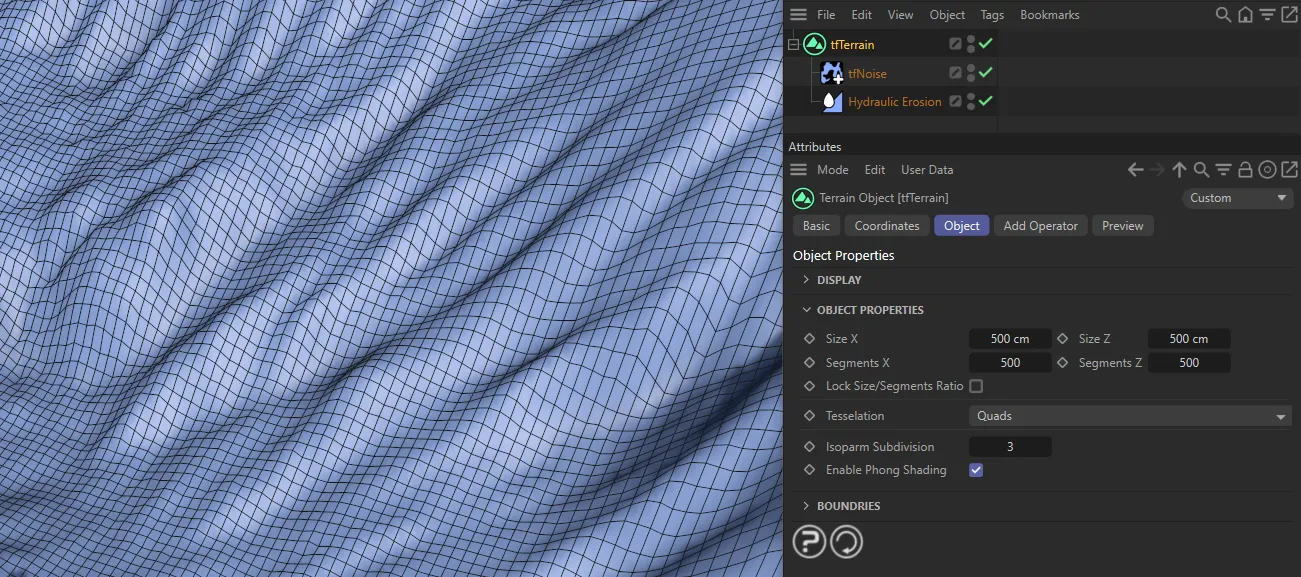
Quad setting in Tessellation.
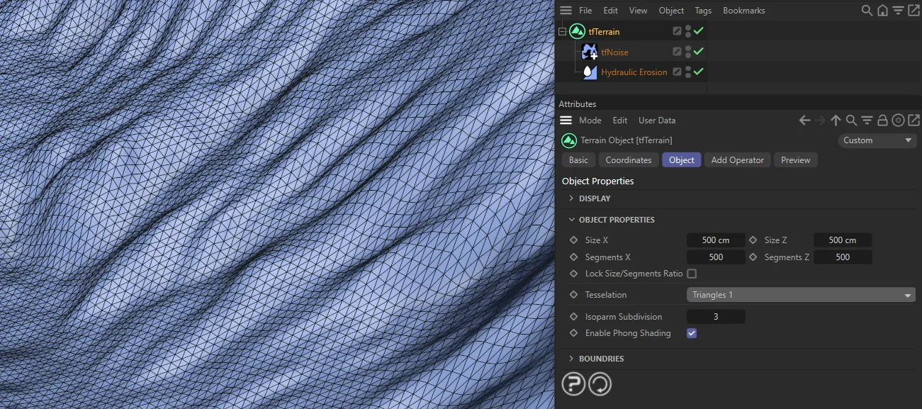
Triangles 1
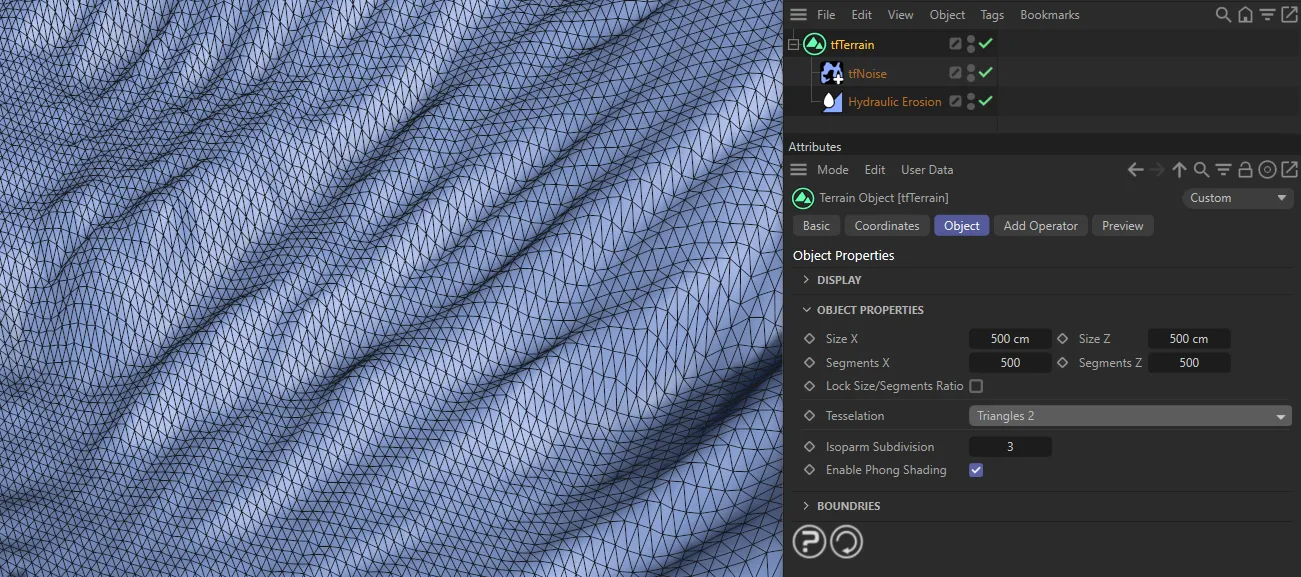
Triangles 2
Isoparm Subdivision
Section titled “Isoparm Subdivision”This defines the number of isoparms, used to display the terrain when the isoparm viewport display mode is active.
Enable Phong Shading
Section titled “Enable Phong Shading”This is on, by default, to apply smooth shading to your scene, but can be disabled.
Boundaries
Section titled “Boundaries”Even Border
Section titled “Even Border”Activating this will generate flat borders, giving your terrain an island look.
Terrain with Even Border selected.
This can be increased, from the default of 0 (zero) cm, to raise the level of the terrain.
It can also be decreased to a negative setting.
There are four options: Legacy, Smooth 1, Smooth 2 and Smooth 3.
The Legacy mode, whilst pulling boundaries down to sea level, also lowers a large part of the central terrain.
The other settings generate smoother results, while letting more of the terrain’s central altitude remain unchanged.
As a result, the border is still even but the landscape retains more of the different gradients.
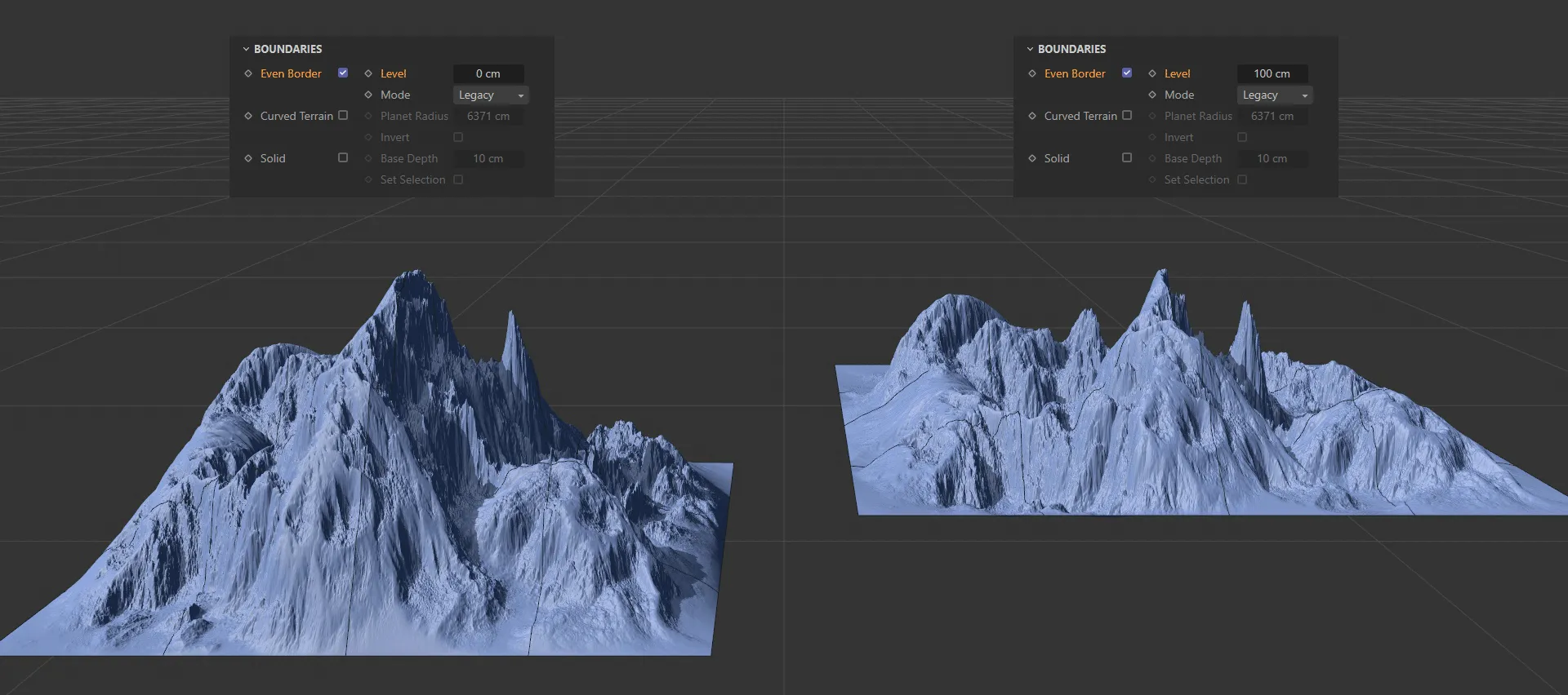
Even Border setting enabled, with a Level of 100cm.
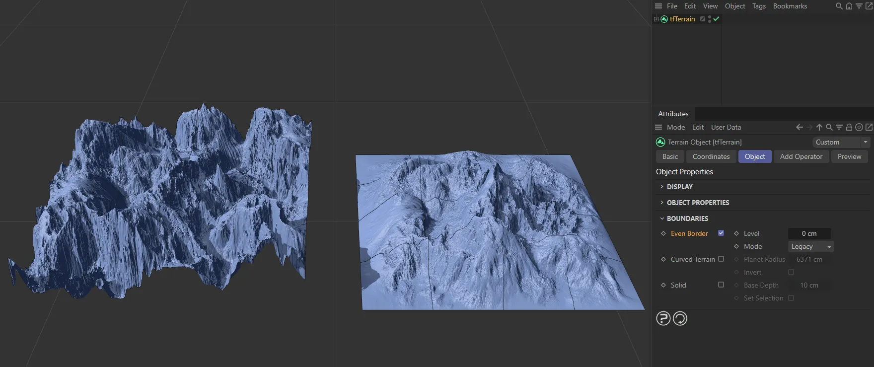
Curved Terrain
Section titled “Curved Terrain”You can simulate large-scale scenes by creating a curved terrain, resembling the curved surface and horizon of an actual planet.
The curvature amount is defined by the Planet Radius setting.
Planet Radius
Section titled “Planet Radius”Set at 6371cm, by default.
Decreasing this will allow a greater curvature of the terrain, as you have - in effect - made the planet smaller.
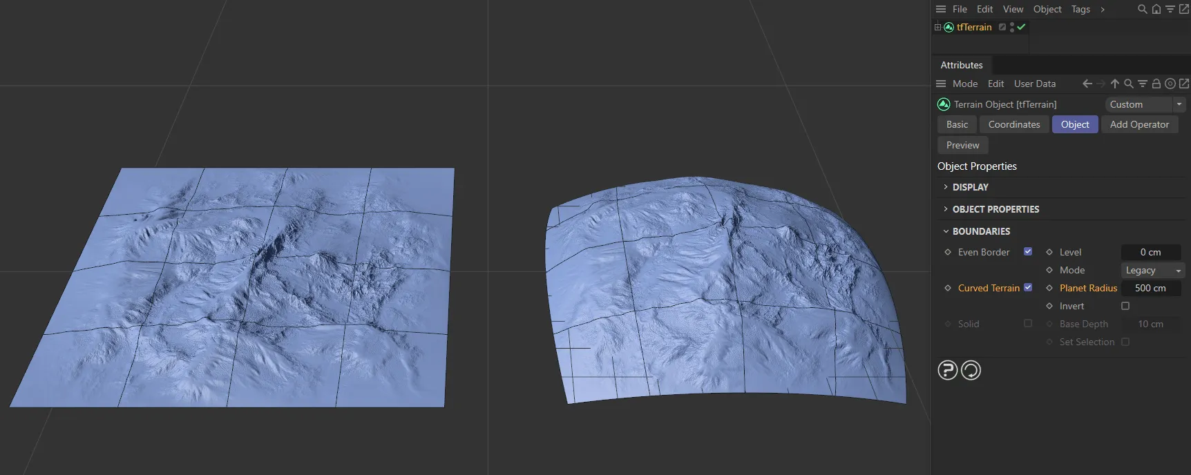
The terrain on the right has Curved Terrain enabled, with Planet Radius set to 500cm.
Invert
Section titled “Invert”Enabling this will invert the curvature of the terrain.
Switching this option on will give a 3D segmented look, as if the terrain has been cut away from the surface of a planet, as below.
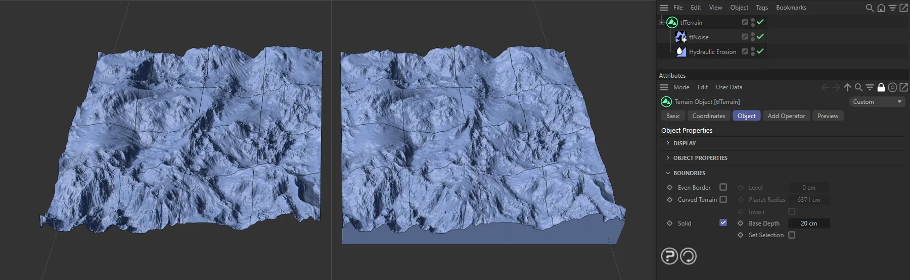
Solid setting is enabled on the right-hand terrain.
Base Depth
Section titled “Base Depth”This can be increased or decreased.
Subdivide Bottom
Section titled “Subdivide Bottom”By default, the bottom face of tfTerrain’s optional solid base consists of only one large polygon
Enabling the Subdivide Bottom option will construct the bottom face using a subdivided plane, much like the terrain top.
While this notably increases memory consumption, it also enables you to deform your terrains without artefacts, or to connect them to a closed polygon object for simulation.
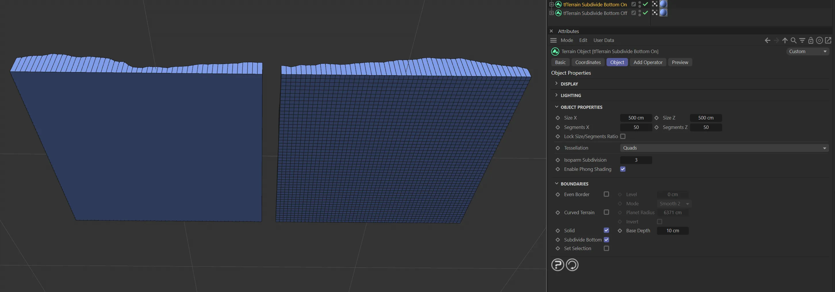
Subdivide Bottom disabled on the left and enabled on the right.
Set Selection
Section titled “Set Selection”Enabling this will give you two selection tags (’b’ and ‘bb’) in the Objects Manager, alongside the tfTerrain object, so that you can apply materials to edge ‘b’ and the base underside ‘bb’.
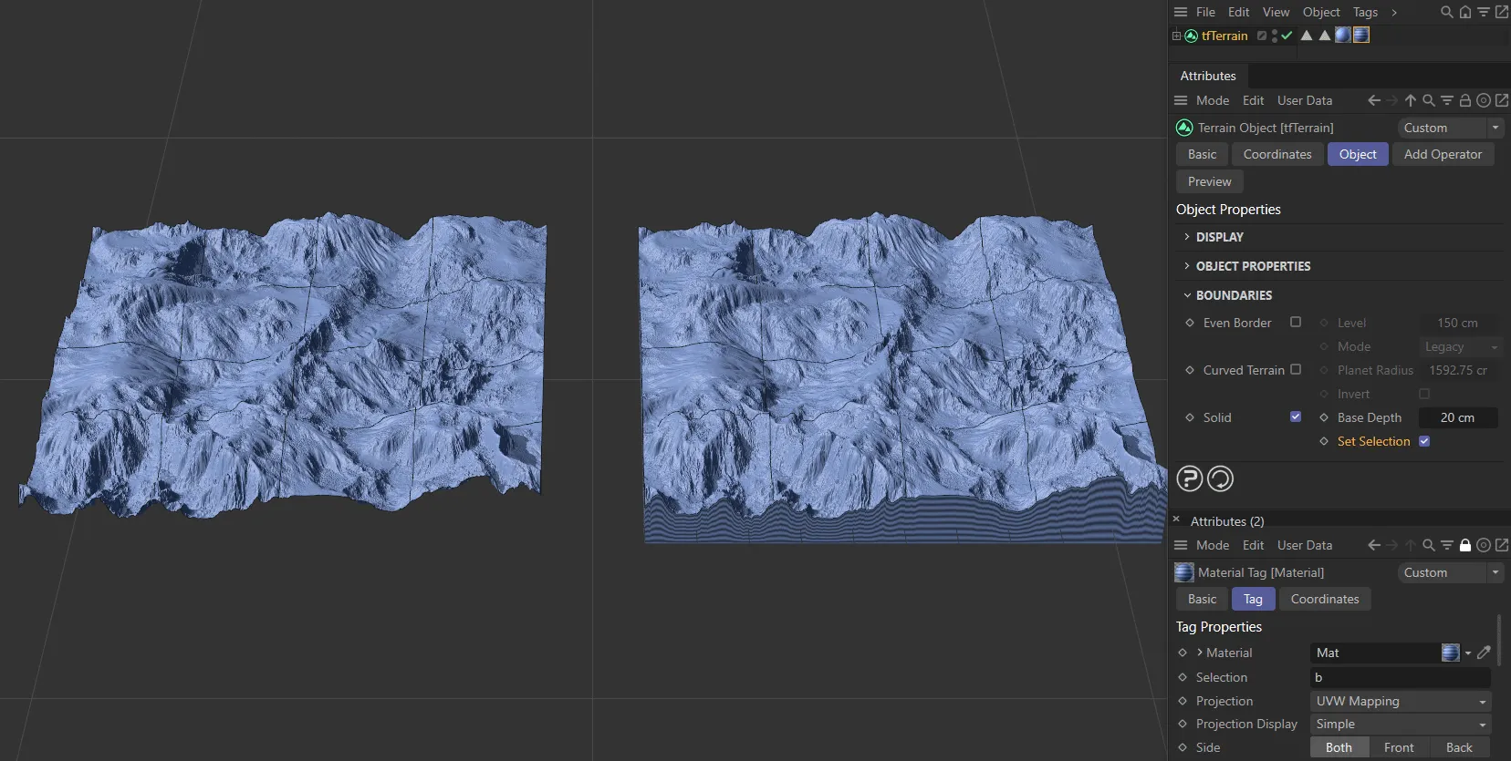
Materials have been applied to the terrain on the right, in Solid setting.
Add Operator tab
Section titled “Add Operator tab”In this tab, you can select and add each of the Generators and Filters.
Individual pages, for each of these, have their own operating instructions.
Copyright © 2026 INSYDIUM LTD. All rights reserved.