Extended Data
This tab deals with additional data which can be generated by the particles.
An X-Particles emitter will always create certain basic data for all particles, such as speed, direction, color, etc.
But in some cases additional data may be required for certain functions.
Always including this data, even when it will never be required, may slow down the particle engine, so this extra data is only stored when required.
In some cases the extra data will be added automatically, but in others you must specify that you require this data.
For example, if you want to use particle rotations, you must enable Use Rotation in the rotation data section of this tab.
General Data tab
Section titled “General Data tab”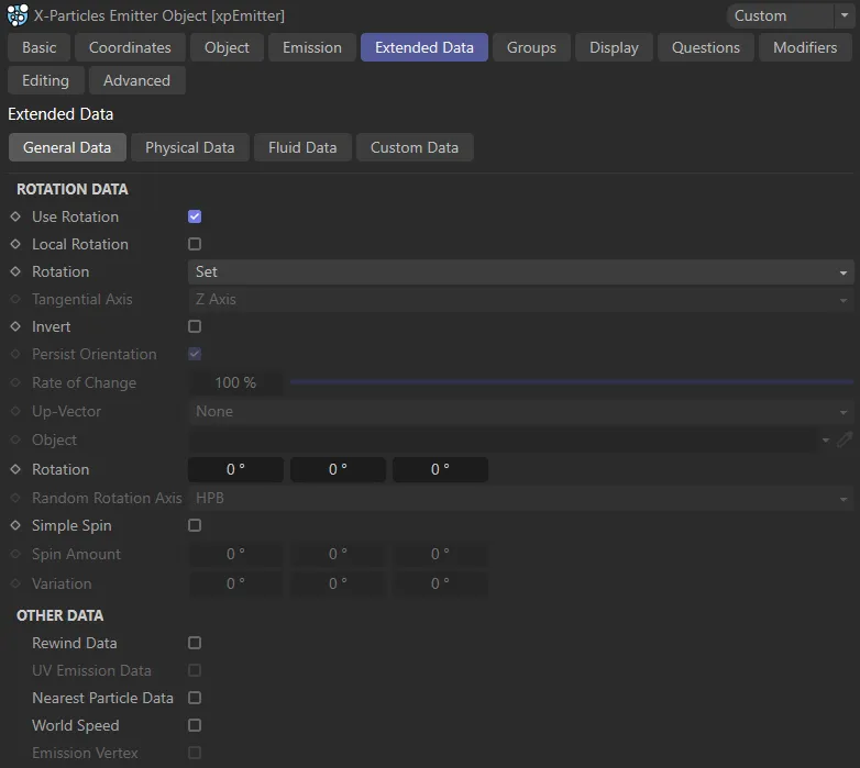
Extended Data tab menu.
Rotation Data
Section titled “Rotation Data”This group of settings determines particle rotation and spin.
If you want to rotate or spin your objects, you must turn on particle orientation in the emitter.
By default, rotation is not enabled since it requires significant extra data to be allocated to the particle.
If you don’t need to rotate the particles or generated objects, leave Use Rotation unchecked.
If an xpSpin modifier is affecting the particles, the modifier will override the Set and Random modes for rotation and will also override the Simple Spin settings.
This is to prevent conflicts between the emitter and the modifier when rotating particles.
Use Rotation
Section titled “Use Rotation”To use particle rotation, check this box.
This is essential if you want to rotate objects linked to the particles, but it uses additional memory so is not enabled by default.
Local Rotation
Section titled “Local Rotation”Enabling this parameter will ensure the correct orientation of ‘stuck’ particles.
Rotation
Section titled “Rotation”In the Set mode, by default.
This animation illustrates the effect of the default settings, with Rotation in the Set mode and Use Rotation disabled.
The other options are: None, Tangential, Random, Face Camera, Face Object, Face Screen and Up Vector.
The particles are not rotated but the necessary data structures are created so that you can use an xpSpin modifier, for example, to spin the particles (and linked objects).
Tangential
Section titled “Tangential”The particles are rotated to align with their direction of travel.
In this animation, Use Rotation is now enabled, with Rotation set to Tangential.
If Persist Orientation is enabled, the particles will be reoriented each frame as their direction changes.
A specific initial rotation can be given to the particles by changing the value in the Orientation field.
An xpSpin modifier, if present, will override this setting.
By direct comparison to the first animation, here Use Rotation is enabled, the Set mode.
Random
Section titled “Random”The particles are given a random initial rotation.
The axis on which the rotation is set can be changed in the Random Orientation drop-down.
An xpSpin modifier, if present, will override this setting.
Again, Use Rotation is enabled in this animation, with the Rotation mode set to Random.
Face Camera
Section titled “Face Camera”The particles are rotated to align their Z-axis towards the current camera.
If Persist Orientation is enabled, the particles will be reoriented each frame as their location and direction (or that of the camera) changes.
Face Object
Section titled “Face Object”The particles are rotated to align their Z-axis towards the object given in the Object field.
If Persist Orientation is enabled, the particles will be reoriented each frame as their location and direction (or that of the object) changes.
This animation shows the effect of the Face Object mode, with particles facing the Cube which has been dropped in the Object field.
Face Screen
Section titled “Face Screen”With this option, the particles always face the current viewport.
This means that they are not rotated, except to face the screen.
This is not the same as facing the camera, since that only rotates the object to point its Z-axis at the camera.
Up Vector
Section titled “Up Vector”This mode deals with the problem of axis flipping (especially on bank) when particles are moving over a surface using the xpFollowSurface modifier.
Often, you will want the particle to maintain the same orientation with respect to the surface, despite changes in direction.
To enable this, select this mode, which will make the Y-axis of the particle perpendicular to the surface.
With all other modifiers it has no effect.
Tangential Axis
Section titled “Tangential Axis”Only available if Rotation Mode is set to Tangential.
With this setting you can align any axis to the direction of travel.
The options are simply the three axes of rotation; the default is the Z-axis.
It can be extremely useful if you have generated objects which need to be aligned along a specific axis.
Invert
Section titled “Invert”If checked, the rotation specified in these settings will be inverted.
Persist Orientation
Section titled “Persist Orientation”Only used in Tangential, Face Camera or Face Object modes.
If it is unchecked, the particles are oriented correctly on birth but are not re-oriented as the scene plays.
If it is checked, the orientation will be constantly maintained and updated.
Rate of Change
Section titled “Rate of Change”Only used in Tangential, Face Camera or Face Object modes.
Changes in particle direction may result in an abrupt snap to a new rotation, but it may be that you would prefer a smoother change in rotation over several frames.
That is what this control does.
A value of 100% will result in an immediate change in rotation.
If the value is 0 (zero), no change in rotation will occur.
Between those values the rotation will change more slowly as the value is decreased, providing a smoother transition.
This animation demonstrates the effect of the Rate of Change parameter, first at 100%, then reduced to 4%.
Up-Vector
Section titled “Up-Vector”Only used in Tangential, Face Camera or Face Object modes.
This parameter sets an up-vector for the rotated particles; essentially, this prevents the particle from banking so that the rotation is constrained to the heading and pitch components.
Set as None, by default. The alternatives are: Y-Positive and Y-Negative.
The up-vector is not used.
Y-Positive and Y-Negative
Section titled “Y-Positive and Y-Negative”The object is the ‘right way up’ when Y-Positive is used but upside down if Y-Negative is selected.
Object
Section titled “Object”Drag the object the particles should face into this field.
Only used in Face Object mode.
Rotation
Section titled “Rotation”You can set the particles to a specific initial rotation in this field.
Only used in Set mode.
Random Rotation Axis
Section titled “Random Rotation Axis”If the Rotation mode is set to Random, the axis or axes to be randomly rotated can be set in this drop-down.
There are seven options representing all possible axis combinations with H, P and B (Heading, Pitch and Bank).
Simple Spin
Section titled “Simple Spin”If you need to make the particles spin, check this box.
You can then set the amount of spin and add some variation between particles, if required.
Animation showing the effect of the Simple Spin setting, enabled.
Spin Amount and Variation
Section titled “Spin Amount and Variation”This is the amount of spin per particle if Simple Spin is enabled.
The Variation setting will give a different spin rate to different particles.
Other Data
Section titled “Other Data”Rewind Data
Section titled “Rewind Data”Check this box to enable data recoding for the xpHistory modifier.
UV Emission Data
Section titled “UV Emission Data”If the particle has been emitted from a polygon object in either Polygon Centre, Polygon Area, Texture, Object Color or Illumination mode, the UV coordinates on the object of the position from which it was emitted will have been generated.
If this is enabled, they will be stored.
You can use the UV data to sample from a texture applied to the object using the UV coordinates at the point of emission.
Then you could use data mapping to map a modifier value to a texture and always sample it at the same point.
This can be very powerful when using an animated texture, for example.
Nearest Particle Data
Section titled “Nearest Particle Data”If checked, this will enable the storage of information about the one particle nearest to and one particle furthest from the emitter (as well as the distance between).
This parameter must be enabled for certain settings to become available and effects to be achieved, such as the one below, where the Gradient Parameter is set to P-P Distance.
The result below is that particles which are closer than 5cm to their nearest particle are yellow and particles which are further than 40cm from their nearest particle are pink, reflecting the Gradient Color (with degrees of color in between) and Min and Max settings in the Display tab.
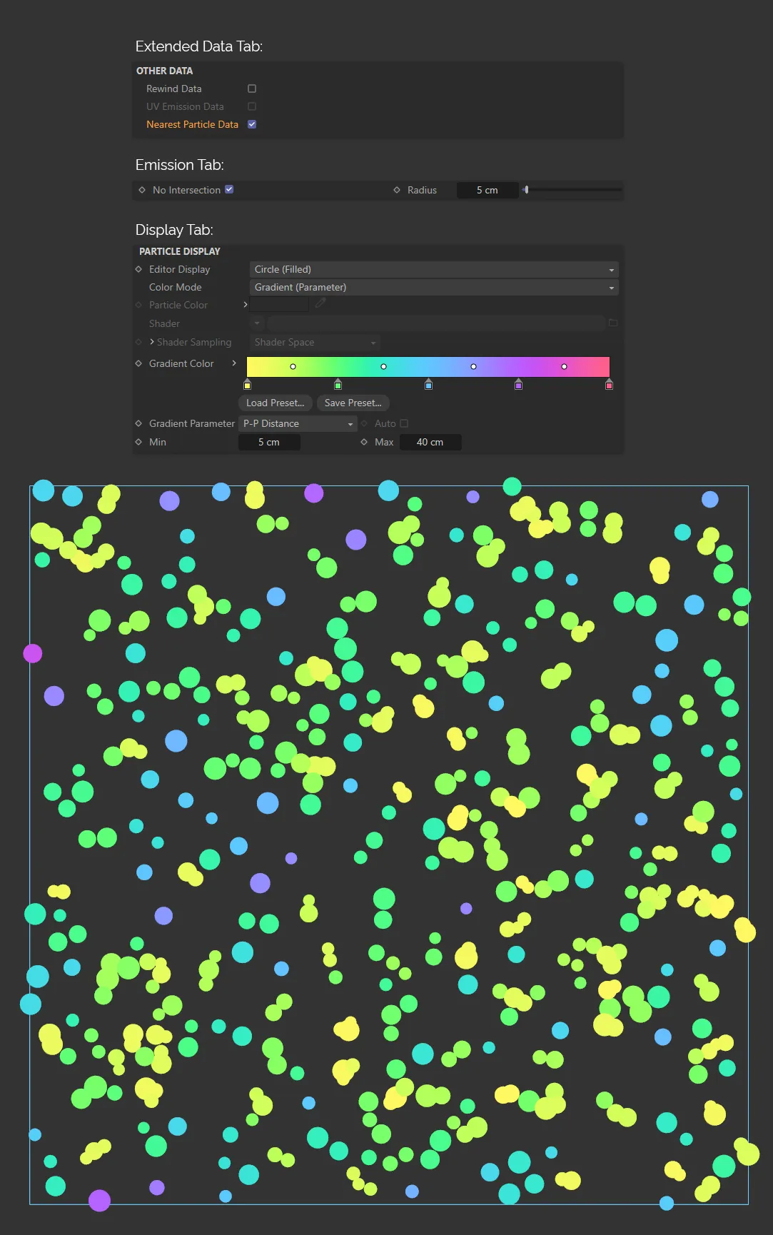
In the image above, Nearest Particle Data is enabled, allowing the scene to be generated through the additional settings in the Display and Emission tabs (as shown).
World Speed
Section titled “World Speed”If particles are stuck to the object from which they are emitted, their speed data will be zero units per second, even if the object itself is moving.
This setting stores the speed of stuck particles as they travel through world space.
This data can then be used in questions and data mapping.
Emission Vertex
Section titled “Emission Vertex”If you emit particles from the vertices of a polygon or point object, checking this box will cause the particle to store the vertex number from which it was emitted.
This can be used, for example, when mapping data to a vertex tag.
Physical Data tab
Section titled “Physical Data tab”In this tab you can set various ‘physical’ properties of the particles.
These are used in ExplosiaFX for smoke, fire, etc.
Particle mass is also used in other areas such as the nxDrag modifier.
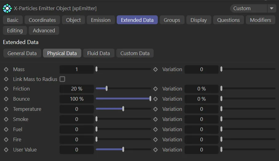
Physical Data tab menu.
All of the following settings can be changed with variation between particles, if required:
Mass and Variation
Section titled “Mass and Variation”The particle’s mass.
This animation demonstrates the effect of the Mass setting on the behaviour of the particles. Both groups have the same 5cm Radius value, with Mass set at 6 on the left, lowered to 0.05 on the right. The denser setting on the left pushes the yellow particles further than the red, on collision.
You can add variation to the mass with the Variation setting.
Link Mass to Radius
Section titled “Link Mass to Radius”If you enable this, the mass of the particle is linked to its radius, so that larger particles have greater mass.
In X-Particles, both mass and radius can be set but if either have any variation included, it is not the case that the largest particles have the greatest mass.
That is what this parameter does: it maps the mass to the radius.
Friction and Bounce
Section titled “Friction and Bounce”These parameters are used to give additional control over friction and bounce on collision.
They are inherent particle parameters which interact with the friction and bounce settings in other X-Particles objects.
If you have set the particle Bounce to 100% the amount of bounce will be completely controlled by the other object - for example, the Collider tag.
This is the default setting.
If you reduce it, then the amount of bounce will be reduced and if it is set to 0 (zero), there will be no bounce at all, no matter what the setting is in any other object.
With friction, both the particle and the surface must have friction greater than 0 (zero) for any friction effect to occur.
This animation illustrates the Friction setting - at 20% on the left and raised to 99% on the right, with a clear effect on the particles progress.
The Bounce setting is 35% on the left then 175% on the right, clearly demonstrating the parameter’s effect.
Temperature, Smoke, Fuel and Burn
Section titled “Temperature, Smoke, Fuel and Burn”These values are all used in the xpExplosiaFX object, when generating fire and smoke.
User Value
Section titled “User Value”This is a value you can set to anything you like and is useful to create customised data mapping techniques.
It can be changed with the Physical modifier or Xpresso, but X-Particles itself will not change it during the course of any simulation.
Fluid Data tab
Section titled “Fluid Data tab”The settings in this quicktab are used in conjunction with the xpFluidFX object.
They are not used with the PBD Fluids object.
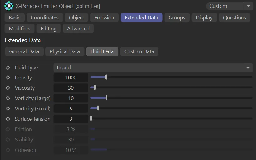
Fluid Data tab menu.
Fluid Type
Section titled “Fluid Type”Set as Liquid, by default.
The alternative setting is Granular.
Liquid
Section titled “Liquid”With this option particle behaviour simulates fluid.
Granular
Section titled “Granular”By contrast, here the particles behave more like solid granules or sand grains than fluids.
Density
Section titled “Density”The density of the liquid expressed as kilograms per cubic metre of liquid.
The default value of 1000 is the density of water (By contrast, the density of mercury is 13,593 kg/cubic metre).
Safe ranges might be a Density of 10 for emitter A and Density 1000 for emitter B, for example.
But if the emitters have very different particle sizes, very large differences in density can cause instabilities, because big particles are much heavier than small particles, even if they have the same density setting.
If a very small particle has a low density setting and a very big particle has a high density setting, the actual difference in density can be extreme and the simulation may explode.
It is better to keep particle sizes closely related across different emitters to keep particle density values closely related.
Viscosity
Section titled “Viscosity”This is the viscosity of the liquid.
Higher values give more viscous liquids.
Vorticity (Large)
Section titled “Vorticity (Large)”This setting refers to large-scale eddies and swirls in the fluid.
Increasing this value will increase their effect.
Vorticity (Small)
Section titled “Vorticity (Small)”This controls small-scale swirls and curls in the liquid and, as with the Vorticity (Large) setting, increasing this value will amplify the effect.
Surface Tension
Section titled “Surface Tension”Surface tension is a force which will always try to minimize the surface area of a fluid.
A fluid has volume and it has surface area.
The perfect shape for a volume is always a sphere, so the more surface tension you apply, the more the fluid will contract and (in zero-gravity) form a sphere.
Friction
Section titled “Friction”This setting is only available if Fluid Type is set to Granular.
It controls the friction of the granular particles as they slide along a surface.
Stability
Section titled “Stability”This setting is only available if Fluid Type is set to Granular.
It represents the ‘stickiness’ of the particles, so the higher it is the greater the tendency to form clumps.
Cohesion
Section titled “Cohesion”This setting is only available if Fluid Type is set to Granular.
The cohesion force is the force which keeps the particles together in clumps.
With a higher cohesion force you will see larger clumps of particles but more particle ‘bouncing’.
Smaller values give a softer sand look with few clumps and less tendency to bounce.
Custom Data tab
Section titled “Custom Data tab”It is possible to add your own custom data to each particle.
Items of custom data are added in this tab.
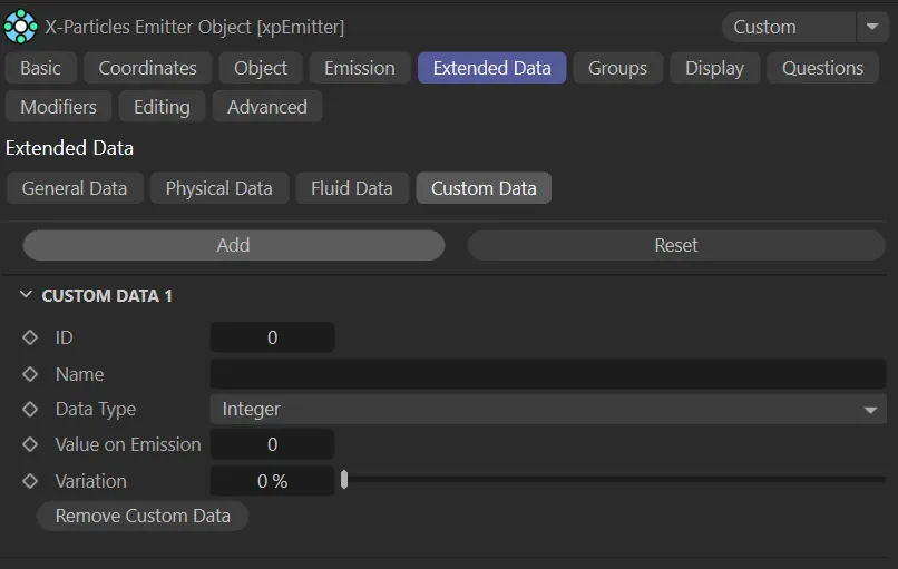
Custom Data tab menu.
Click this button to add a new item of custom data.
The interface will then change to look like the above image.
You can click the Add button again to add as many items of custom data as required.
You can remove data items individually once they have been added using the Remove Custom Data button in each custom data section.
Remove
Section titled “Remove”Remove all custom data by clicking the Reset button.
This is the ID number for each custom data item.
You can leave this at 0 (zero), but if you do then you must enter a name for the data item in the Name field.
Otherwise the data items will all look the same to the Question, Custom Data Modifier and Action objects and they will work only on the first data item in the list.
If you prefer to work with ID numbers, set this to a number of your choice; it should be unique to this data item.
You can also set this to -1, which will force X-Particles to ignore the ID value and only use the Name setting to identify the data item.
Alternatively, you can identify the data item by name, by entering any text string here.
Data Type
Section titled “Data Type”Set as Integer, by default.
This is the type of data the custom data item will hold.
The other options are: Float, Matrix, String, Time and Vector.
Integer
Section titled “Integer”A whole number, such as 1, 5, 17, etc.
A floating-point number, such as 1.0, 2.5, 3.1416, etc.
Matrix
Section titled “Matrix”A Cinema 4D Matrix field.
String
Section titled “String”Any string of text.
A time field specifically for time values (showing either frames or seconds, depending on your Cinema 4D preferences setting).
Vector
Section titled “Vector”A Cinema 4D Vector field.
Value on Emission
Section titled “Value on Emission”When a particle is created, the custom data item will have this initial value.
This can then be changed and tested for, as with the inbuilt data items such as speed, radius, etc.
Variation
Section titled “Variation”This field is available if Data Type is set to anything other than Matrix or String.
It adds variation to the custom data item so that different particles receive different values on emission.
Remove Custom Data
Section titled “Remove Custom Data”Click this button to remove this custom data item, leaving the others intact.
Copyright © 2026 INSYDIUM LTD. All rights reserved.