nxExplosiaFX
nxExplosiaFX is an intuitive GPU powered tool used for the simulation of smoke and fire from a source object, particle or spline.
Simulation tab
Section titled “Simulation tab”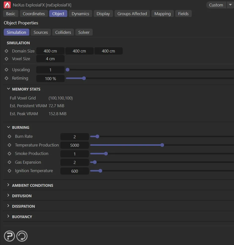
nxExplosiaFX Simulation tab.
Domain Size
Section titled “Domain Size”This can be set manually, in the boxes provided, or by dragging the ‘handles’ on the bounding box in the scene.
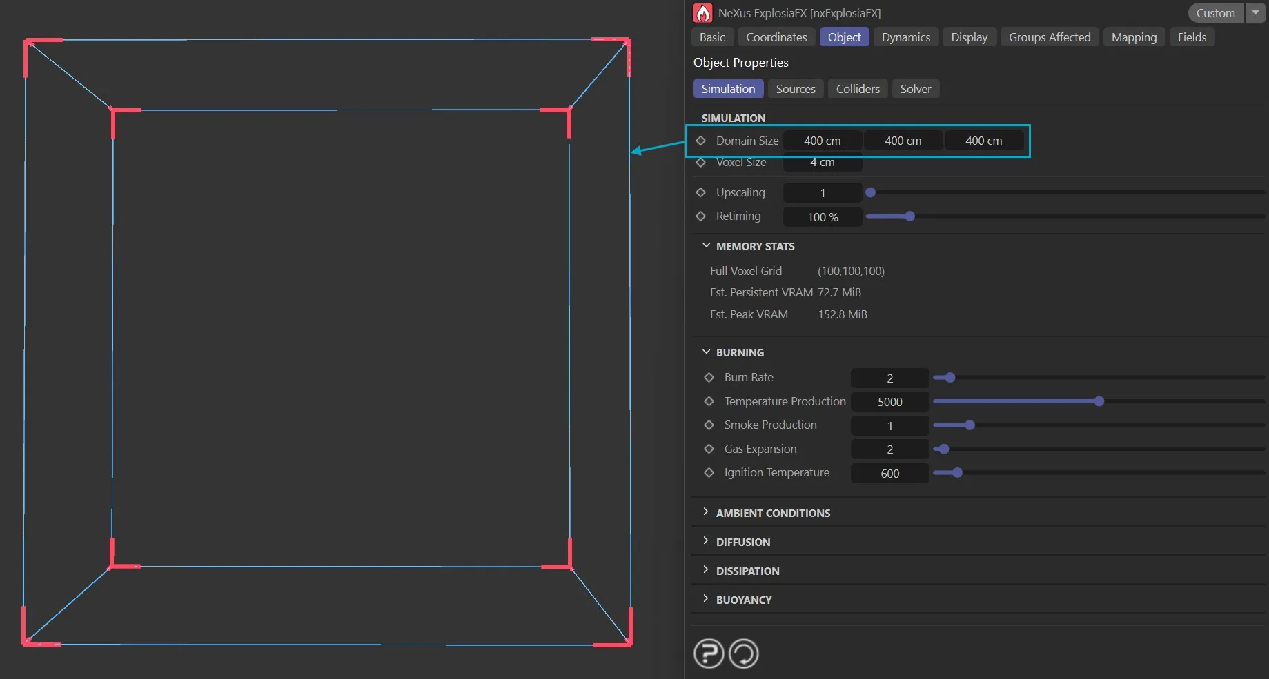
nxExplosiaFX Domain Size.
Voxel Size
Section titled “Voxel Size”This is the voxel size within the boundaries of the solver.
The solver volume is divided into cubes of this size.
Smaller values result in more accurate/detailed simulations but are slower to playback and render.
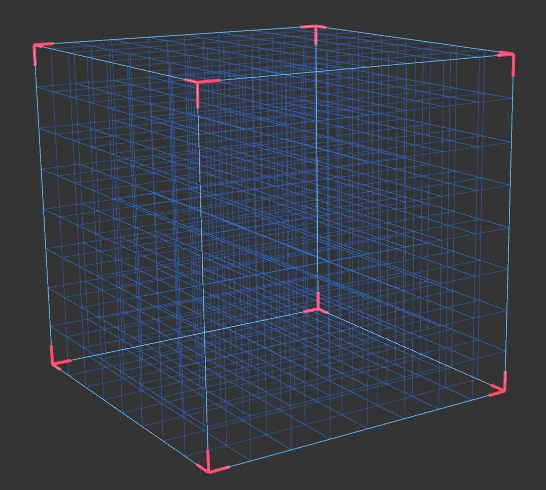
nxExplosiaFX voxel display with Voxel Size set to 50cm.
Upscaling
Section titled “Upscaling”This increases the spatial resolution of the voxel grid to add more detail while retaining the broad features and shaping of the base-resolution simulation.
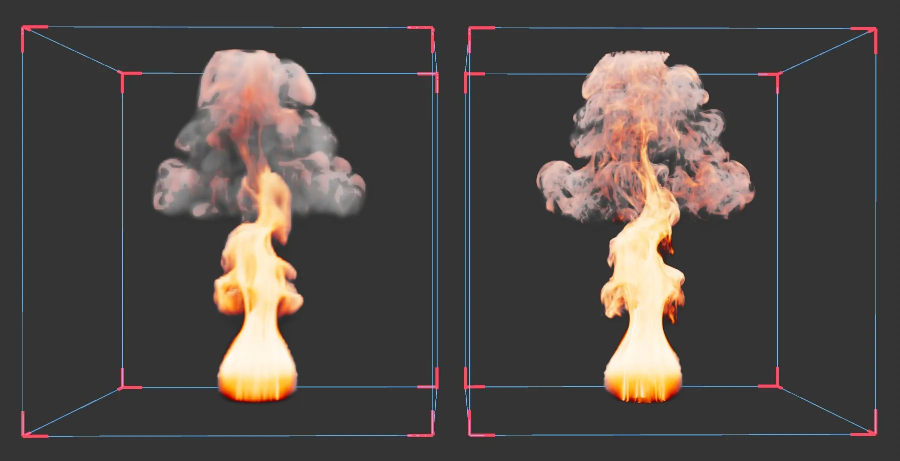
nxExplosiaFX with the same simulation, using 3cm voxels. The right image has Upscaling set to 3.
Retiming
Section titled “Retiming”This speeds up or slows down the pacing of the simulation.
100% is the natural timing, 200% doubles the speed of the dynamics, 50% halves the speed of the dynamics.
Memory Stats
Section titled “Memory Stats”These are statistics regarding memory use and processing time and are updated as the simulation runs.
Burning
Section titled “Burning”These settings provide a simulation around what happens when fuel ignites.
Burn Rate
Section titled “Burn Rate”The rate at which available fuel is burnt.
Temperature Production
Section titled “Temperature Production”Simulates the temperature of the ‘burn’.
Smoke Production
Section titled “Smoke Production”The amount of smoke produced by the ‘burn’.
Gas Expansion
Section titled “Gas Expansion”This setting simulates the level of explosivity.
Ignition Temperature
Section titled “Ignition Temperature”The temperature threshold at which emitted fuel will ignite and begin to burn.
Ambient Conditions
Section titled “Ambient Conditions”These settings relate to the ‘background’ temperature and fuel concentration in the broader environment, far away from EFX emission sources.
Temperature, Fuel
Section titled “Temperature, Fuel”These set the background temperature and fuel concentration in the broader environment, which can have a subtle effect on the simulation source.
The Fuel value also acts as the minimum fuel threshold for dissipation. Voxels with a fuel value at or below this level will not be affected by Fuel Dissipation.
Diffusion
Section titled “Diffusion”Diffusion in nxExplosiaFX can be thought of as the rate of movement of a parameter, such as smoke or heat, throughout the solver.
The higher these values are, the greater the even distribution of the parameter and so the less contrast you will see in the result.
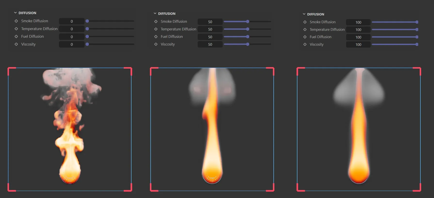
nxExplosiaFX, with the same simulation, using 3cm voxels and Diffusion set to 0, 50 and 100*.*
Smoke Diffusion, Temperature Diffusion, Fuel Diffusion
Section titled “Smoke Diffusion, Temperature Diffusion, Fuel Diffusion”The diffusion values for smoke, temperature and fuel respectively.
Viscosity
Section titled “Viscosity”This setting is labelled Viscosity but it is actually another diffusion setting, this time for velocity.
As you might expect, increasing this value smooths out movement and gives the impression of a thicker, more viscous medium.
Dissipation
Section titled “Dissipation”These values control the dissipation of a parameter, the effect being to reduce it over time.
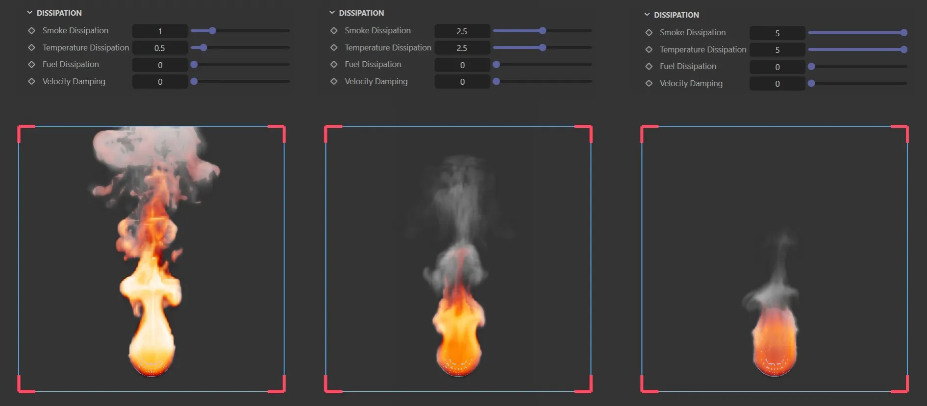
nxExplosiaFX, with the same simulation, using 3cm voxels, adjusting Smoke Dissipation and Temperature Dissipation.
Smoke Dissipation, Temperature Dissipation, Fuel Dissipation
Section titled “Smoke Dissipation, Temperature Dissipation, Fuel Dissipation”The dissipation values for smoke, temperature and fuel respectively.
Velocity Damping
Section titled “Velocity Damping”This setting acts to reduce velocity over time.
Buoyancy
Section titled “Buoyancy”Gravity
Section titled “Gravity”Gravity is inherent in nxExplosiaFX so an nxGravity modifier is not needed.
This is the gravity strength on the positive Y axis.
Smoke Buoyancy
Section titled “Smoke Buoyancy”Smoke rises due to the heat of burning.
This value can reduce or increase the smoke buoyancy, so it will rise slower or faster.
nxExplosiaFX smoke only with simulation setting Smoke Buoyancy to -1.
Temperature Buoyancy, Fuel Buoyancy
Section titled “Temperature Buoyancy, Fuel Buoyancy”The same as for the smoke buoyancy, but for heat and fuel respectively.
Sources subtab
Section titled “Sources subtab”This subtab is where the source(s) of the simulation are set and finetuned.
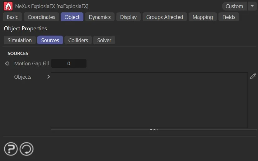
The Sources tab settings.
Motion Gap Fill
Section titled “Motion Gap Fill”If sources in the scene are moving quickly, applying their emission once per frame will leave gaps.
Applying a value in this setting will fill the gaps with additional inter-frame images of the source.
For mesh sources, the numerical value sets the number of additional images.
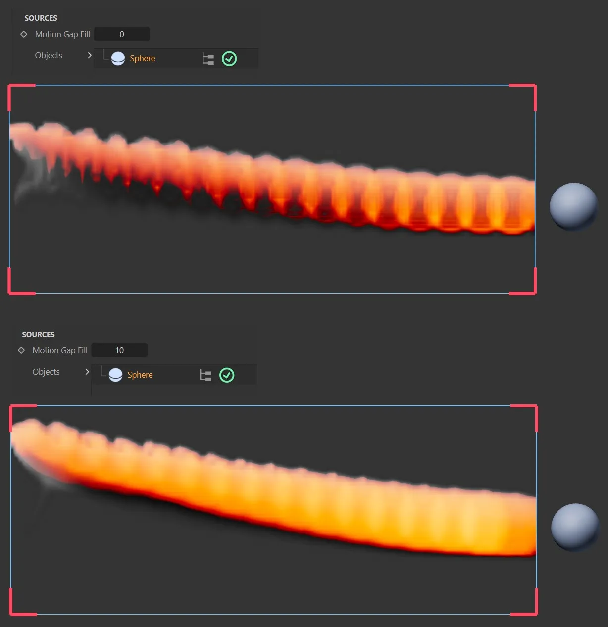
These two images have the same simulation settings, with Motion Gap Fill at 0 (zero) and 10. **
Objects
Section titled “Objects”The list of source objects.
If the object has a green check mark icon, it will be used as a source; if it has a red ‘x’ icon, it will not be used.
Emit From
Section titled “Emit From”This is set as Surface by default but can be changed to Volume, to explode from within the scene object.
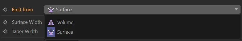
The nxExplosiaFX Emit from menu, showing the two modes Volume and Surface.
Surface Width
Section titled “Surface Width”Only available with the Emit From set as Surface, this setting presents a level of ‘padding’ between the surface area of the scene object and the ‘burn’ visual, allowing more fuel to access the surface area.
Surface Width relates to the size of the zone around the mesh surface that emits at full strength (measured in voxel spacings).
Taper Width
Section titled “Taper Width”Taper Width is an additional smoothing region that extends farther and gradually reduces to zero emission strength.
The parameters available below will differ slightly, depending on the object recognised in the Objects list.
Controls the level of smoke produced.
By clicking on the black arrow next to Smoke, two further parameter options become available.
This is how the emission is displayed.
The options are: Set, Blend, Add / sec and Sub. / sec.
The default, this sets the amount per frame.
Rather than overwriting the channel value absolutely, this blends the emission with any existing value in that voxel. This is generally the better choice when multiple source objects overlap.
Add / sec, Sub. / sec
Section titled “Add / sec, Sub. / sec”Adds or subtracts the channel set, per second.
Weight by
Section titled “Weight by”Set as None, by default, the smoke is uniformly emitting across the surface of the object.
The smoke can also be weighted by the other settings: Tag, Texture or Noise.
Each of these settings will allow the usual C4D options to add further detail.
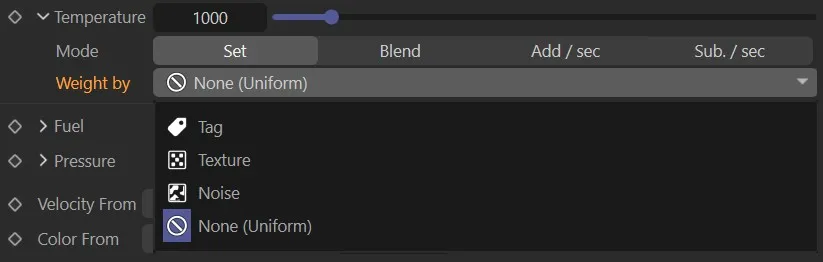
The nxExplosiaFX Weight by options*.*
Temperature, Mode, Weight by
Section titled “Temperature, Mode, Weight by”Sets the ‘burn’ temperature.
The Mode and Weight by settings are explained above.
Fuel, Mode, Weight by
Section titled “Fuel, Mode, Weight by”Controls the amount of fuel in the solve, affecting the flames produced.
The Mode and Weight by settings are explained above.
Fuel Frame Limit, Start, End
Section titled “Fuel Frame Limit, Start, End”This is an additional setting available with Fuel to avoid having to keyframe or data map the Fuel value.
The Start and End relate to the frames.
Pressure, Mode, Weight by
Section titled “Pressure, Mode, Weight by”Simulates air pressure levels in the solve.
The Mode and Weight by settings are explained above.
Pressure Frame Limit, Start, End
Section titled “Pressure Frame Limit, Start, End”This additional setting is also available with Pressure to avoid having to keyframe or data map the Pressure value.
The Start and End relate to the frames.
Velocity
Section titled “Velocity”This option appears with a spline or emitter source.
Controls the velocity imparted to the fluid from the source.
Velocity From
Section titled “Velocity From”Set as Object Motion, by default.
The other options are Mesh Normal or Custom.
Each of them then give an additional percentage or cm setting to fine tune.
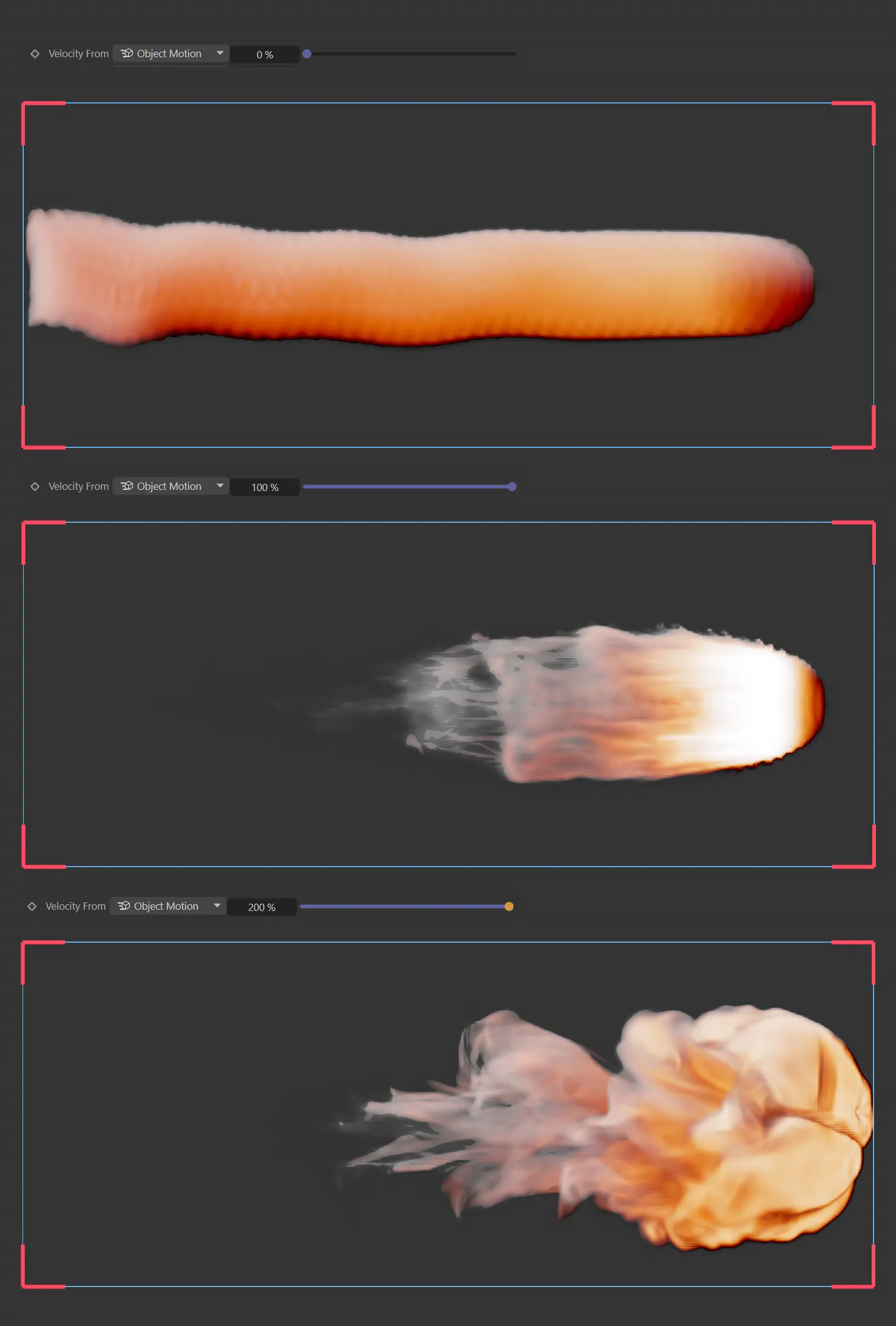
nxExplosiaFX Velocity From set to Object Motion, using 0, 100 and 200%.
This option appears with a spline or emitter source and controls the amount of color displayed.
0 (zero) means no color is displayed and 100% is a full viewport display.
Color From
Section titled “Color From”Set as Object, by default.
This can also be set to Shader or Custom.
Each option also gives additional settings to further control the color.
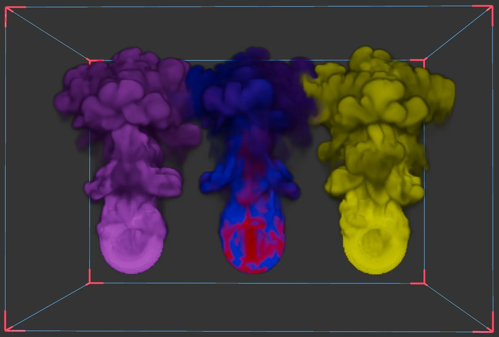
nxExplosiaFX, showing each Color mode: Object, Shader and Custom.
To view color
Section titled “To view color”To view color in the simulation, these steps are required:
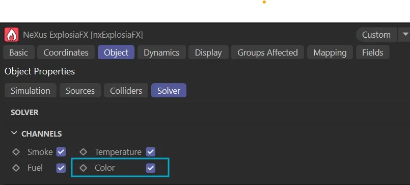
1: In the Solver tab > Channels, enable the Color option.
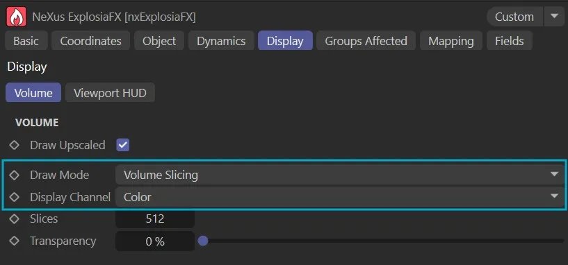
2: The viewport drawing must to be set as follows: Draw Mode as Volume Slicing and Display Channel as Color.
Colliders subtab
Section titled “Colliders subtab”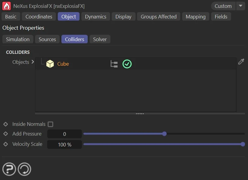
The Colliders tab settings.
Objects
Section titled “Objects”Any object dropped into this list will interact as a collider object.
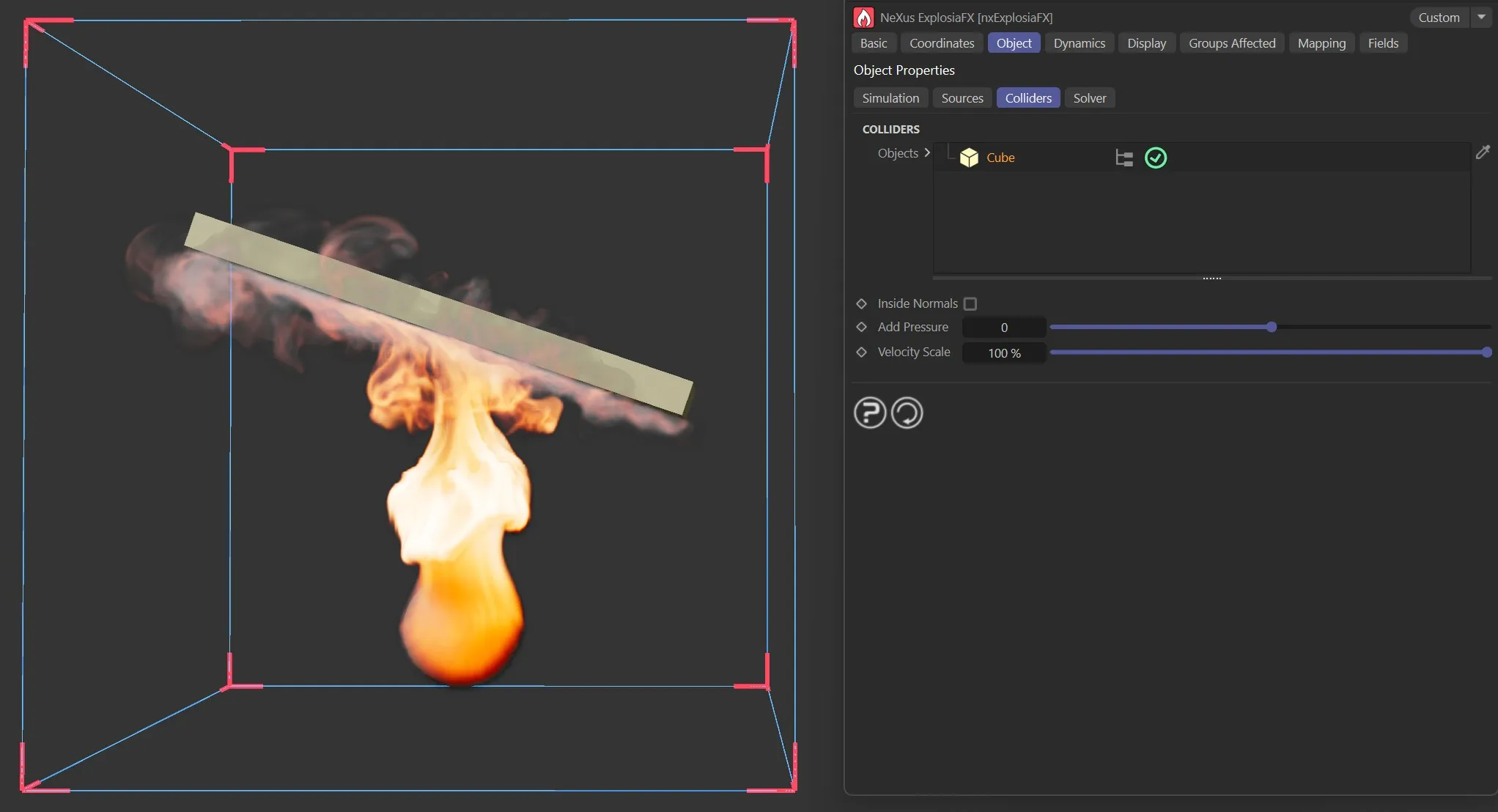
Colliders tab, showing collisions with a Cube object.
Inside Normals
Section titled “Inside Normals”When this is enabled the inside facing ‘normals’ of an object are used.
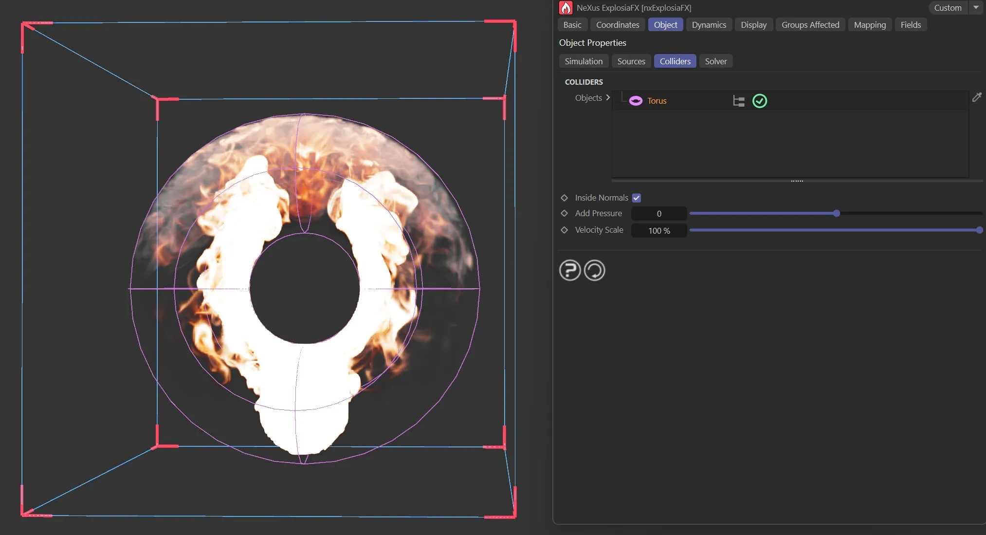
Colliders tab, showing collisions with a Torus, with Inside Normals enabled.
Add Pressure
Section titled “Add Pressure”This setting pushes the fluid simulation away from the collider.
Larger pressure values give a stronger push.
Negative pressure attracts the fluid to the collider.
Velocity State
Section titled “Velocity State”At 100%, a moving collider will transfer its velocity to the fluid simulation.
Changing the scale value pre-scales the velocity before transferring to the fluid.
Solver subtab
Section titled “Solver subtab”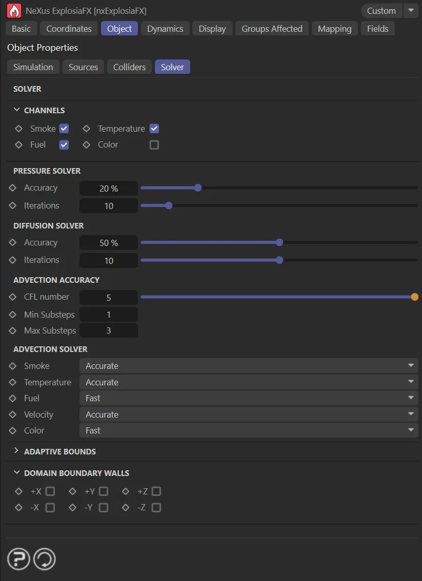
The Solver tab settings.
Channels
Section titled “Channels”These checkboxes indicate which channels are used in the simulation.
The default is for smoke, temperature and fuel to be checked.
Smoke, Temperature, Fuel
Section titled “Smoke, Temperature, Fuel”In fire simulations, a fire requires fuel to burn and heat to ignite the fuel.
This may then generate smoke, or it may not, and you can turn smoke off if desired.
But if you turn off fuel, there is nothing to burn and you won’t see the fuel or smoke even though there is still heat from the temperature level.
Turn off the temperature and there’s nothing to ignite the fuel, so you will see nothing happening at all.
As an example, if you are set to display fuel and smoke, then you uncheck Smoke in this tab, you will only see the fuel display, as no smoke will be generated.
If you check this box, to add the color channel to the solver, you can specify a specific color to be used in the display.
To do this, you would also need to set the Color setting in the Display tab.
Pressure Solver
Section titled “Pressure Solver”Accuracy, Iterations
Section titled “Accuracy, Iterations”The Pressure Solver aims to keep the fluid incompressible during its flow.
The method used to solve for the pressure field is iterative and the iterations terminate when the accuracy setting is met, or when the maximum iterations are reached.
Diffusion Solver
Section titled “Diffusion Solver”Accuracy, Iterations
Section titled “Accuracy, Iterations”The Diffusion Solver is used when diffusion is enabled in the Simulation tab.
Diffusion causes the density in different channels to smoothen and spread out.
This solver is also iterative, and the iterations terminate when the accuracy setting is met, or when the maximum iterations are reached.
Advection Accuracy
Section titled “Advection Accuracy”Advection is the process of the transport of some quantity - e.g. smoke or velocity - through a fluid or gas, by motion.
The different channel weights (smoke, fuel, temperature, color) are transported by the movement of the background fluid.
CFL Number
Section titled “CFL Number”The CFL Number determines how the simulation automatically and adaptively chooses the number of subframe steps based on an analysis of the motion.
The solver will allow the fastest moving part of the fluid to move a distance (measured in voxel spacings) equal to ‘CFL Number’ in one time step.
If the fluid is moving fast enough that this distance is exceeded, additional subframe steps will be added (up to the maximum) to more-accurately track the motion.
Min Substeps, Max Substeps
Section titled “Min Substeps, Max Substeps”When the fluid is moving quickly, tracking the motions accurately will require inserting additional solver steps for each frame advance.
The maximum and minimum number of sub-frame steps can be selected here.
Advection Solver
Section titled “Advection Solver”Smoke, Temperature, Fuel, Velocity, Color
Section titled “Smoke, Temperature, Fuel, Velocity, Color”nxExplosiaFX carries out advection for these different properties.
For each one there is the choice of algorithm: Fast or Accurate.
The fastest algorithm and the best choice for Temperature advection.
It is also recommended for Color.
Accurate
Section titled “Accurate”The slower algorithm and the most memory-intensive, this is the most detailed and is therefore recommended for Smoke and Fuel advection simulations, for which fine detail is important.
Adaptive Bounds
Section titled “Adaptive Bounds”When solving the simulation, you could simply solve each voxel inside the bounds, but that would be slow and inefficient.
Instead, you can solve only those voxels where something is happening, adjusting the volume to be solved as the simulation progressed.
This is what adaptive bounds does.
In general you should leave this enabled unless you require the whole solver volume to be solved each iteration, but doing that will be significantly slower than using adaptive bounds.
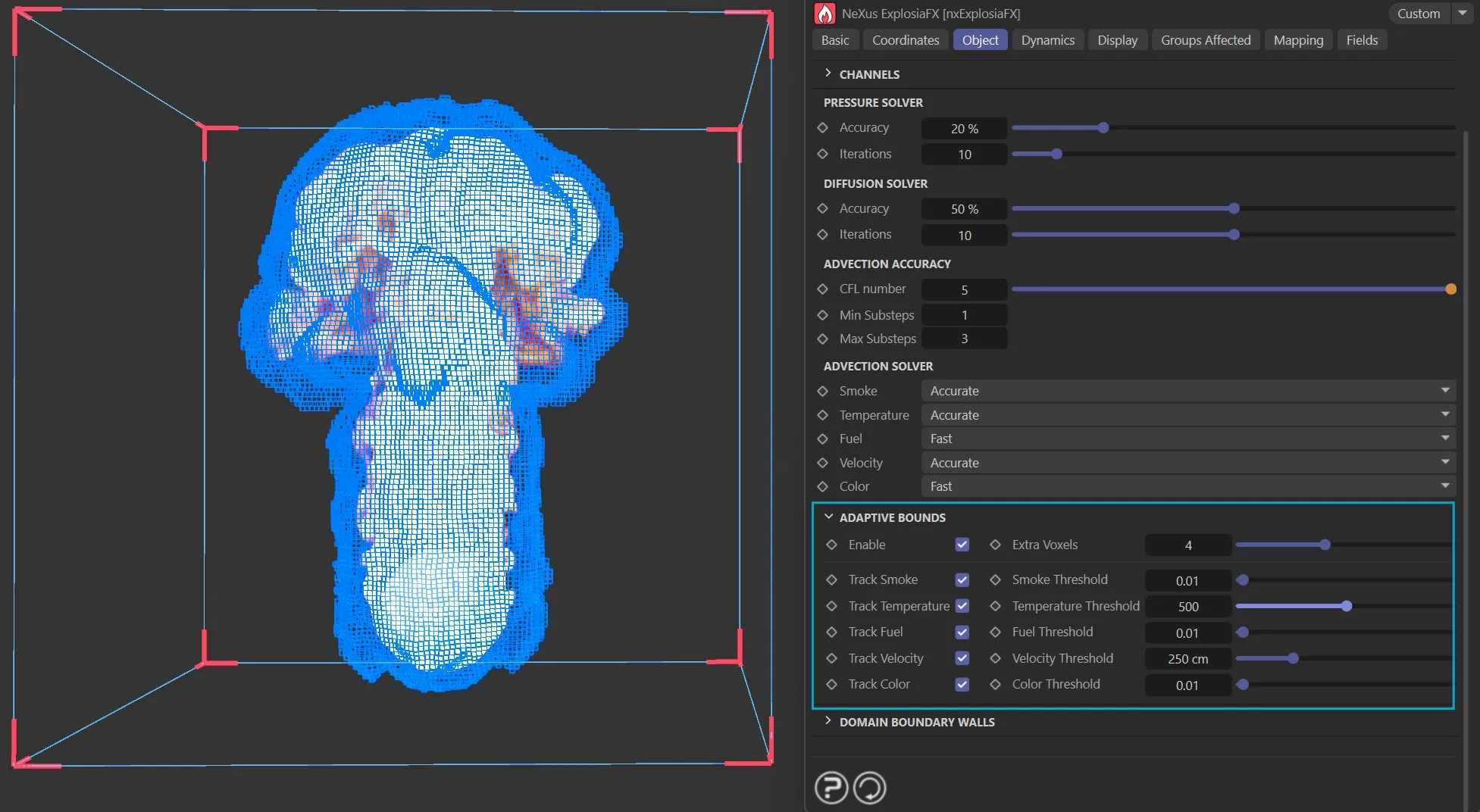
The Solver tab, Adaptive Bounds options, using the display options to view them.
Enable
Section titled “Enable”Check this box to enable adaptive bounds.
Extra Voxels
Section titled “Extra Voxels”Set at 4, by default, this affects the size within the boundaries of the solver as the simulation progresses.
Track Smoke, Track Temperature, Track Fuel, Track Velocity, Track Color
Section titled “Track Smoke, Track Temperature, Track Fuel, Track Velocity, Track Color”To adjust the bounds the solver must keep track of some parameter, such as smoke or fuel.
With these settings you can choose which parameters the solver will track.
Smoke Threshold, Temperature Threshold, Fuel Threshold, Velocity Threshold, Color Threshold
Section titled “Smoke Threshold, Temperature Threshold, Fuel Threshold, Velocity Threshold, Color Threshold”These are the minimum values of a tracked parameter, which must be present in a voxel before a change in bounds takes place.
If these values are never exceeded, the bounds will never change.
For example, if you track only the temperature, the temperature value in any voxel must reach the temperature threshold level to trigger the adaptive bounds.
Domain Boundary Walls
Section titled “Domain Boundary Walls”+X, -X, +Y, -Y, +Z, -Z
Section titled “+X, -X, +Y, -Y, +Z, -Z”These options will enable the domain walls to be opened and closed.
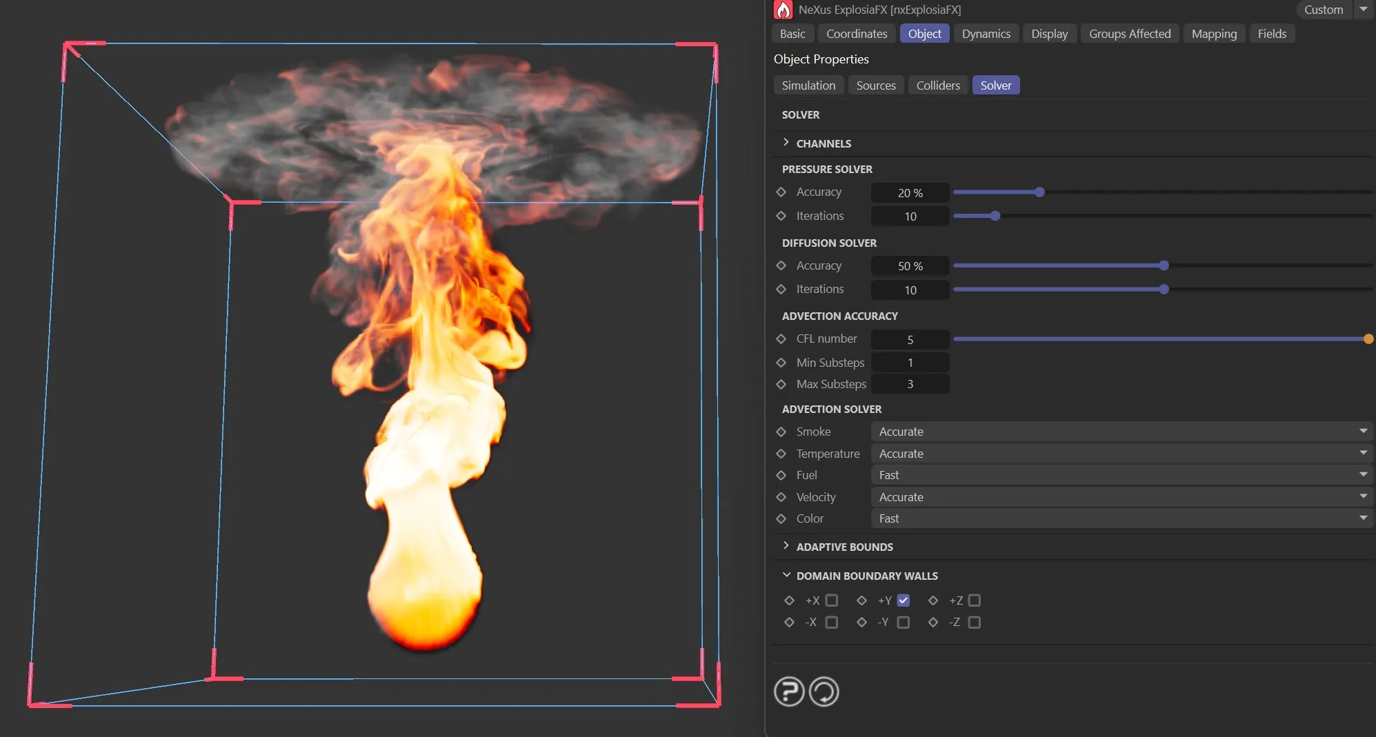
The Solver tab, Domain Boundary Walls set with + Y enabled.
Dynamics tab
Section titled “Dynamics tab”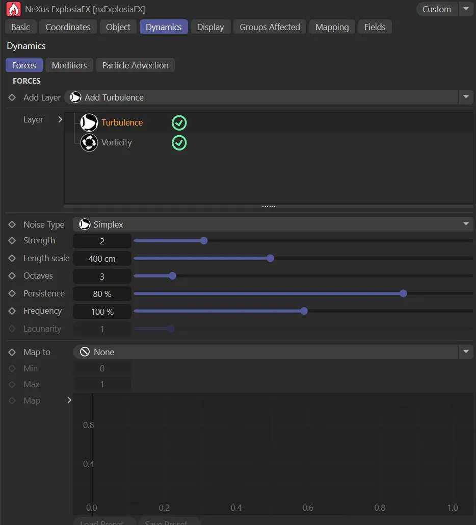
The Dynamics tab, with the Forces subtab UI.
Forces subtab
Section titled “Forces subtab”Add Layer
Section titled “Add Layer”By clicking on this button, forces layers can be added.
The options are: Add Turbulence, Add Vorticity and Add Wind.
Each one of these layers has their own parameter settings, which are explained below.
The Layer list is populated with Turbulence and Vorticity layers, by default.
They can, of course be disabled, by clicking on the green check (turning it into a red ‘x’).
Alternatively, if either layer is not required, they can be deleted.
Turbulence layer options
Section titled “Turbulence layer options”Noise Type
Section titled “Noise Type”Set as Simplex, by default,
The other options are: Turbulence, Wavy Turbulence, Voronoise, FBM and Cubic.
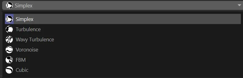
Noise Type options.
Strength
Section titled “Strength”Sets the strength of the turbulence.
Length Scale
Section titled “Length Scale”This the scale of the noise.
Octaves
Section titled “Octaves”Octaves determine the level of fine detail.
Persistence
Section titled “Persistence”Regulates how the turbulence strength persists through multiple octaves.
Frequency
Section titled “Frequency”Sets levels of animation by altering the speed of the turbulence.
Lacunarity
Section titled “Lacunarity”Controls how quickly the frequency increases with each successive octave.
Map to
Section titled “Map to”Here, the following options can be added: Smoke, Temperature, Fuel, Color (R), Color (G), Color (B), Velocity (Local x), Velocity (Local y), Velocity (Local z), Speed, Position (Local x), Position (Local y), Position (Local z), Pressure and Document Time.
When set in the default, None, the three parameters below are greyed out.
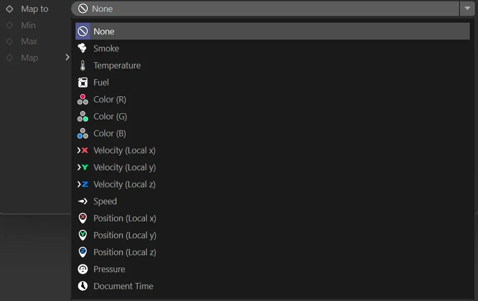
In the Dynamics tab, the available Map to maps.
Min, Max
Section titled “Min, Max”Minimum and maximum levels can be set here to fine-tune the mapping.
What is shown in this grid will depend on the mapping option chosen.
This can then be adjusted to meet whatever simulation is required.
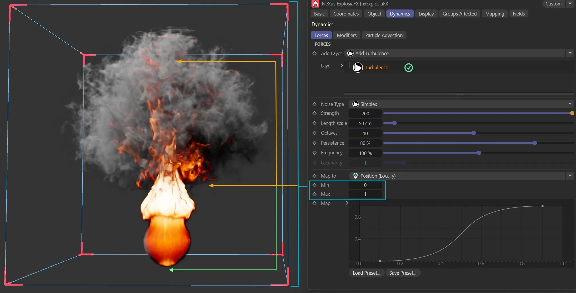
In the Dynamics tab, showing the Turbulence layer mapped to Position (Local y), the strength of the turbulence set happens only halfway up the domain volume.
Vorticity layer options
Section titled “Vorticity layer options”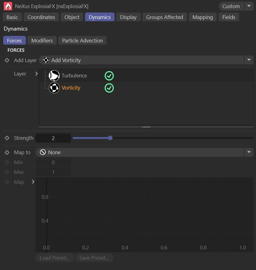
Vorticity layer options in the Forces subtab.
Strength
Section titled “Strength”Amplifies existing rotational motion in the velocity field, enhancing swirling detail that would otherwise be lost to numerical dissipation.
Map to, Min, Max, Map
Section titled “Map to, Min, Max, Map”These parameters offer the same mapping options as the ones in the Turbulence layer.
Wind layer options
Section titled “Wind layer options”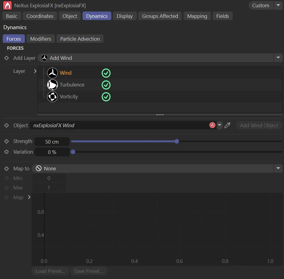
Wind layer options in the Forces subtab.
Object
Section titled “Object”The wind object is added to the link.
Add Wind Object
Section titled “Add Wind Object”Clicking this button will add a wind object to the scene.
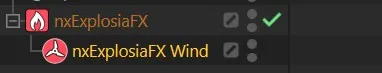
Wind object added to the Object Manager.
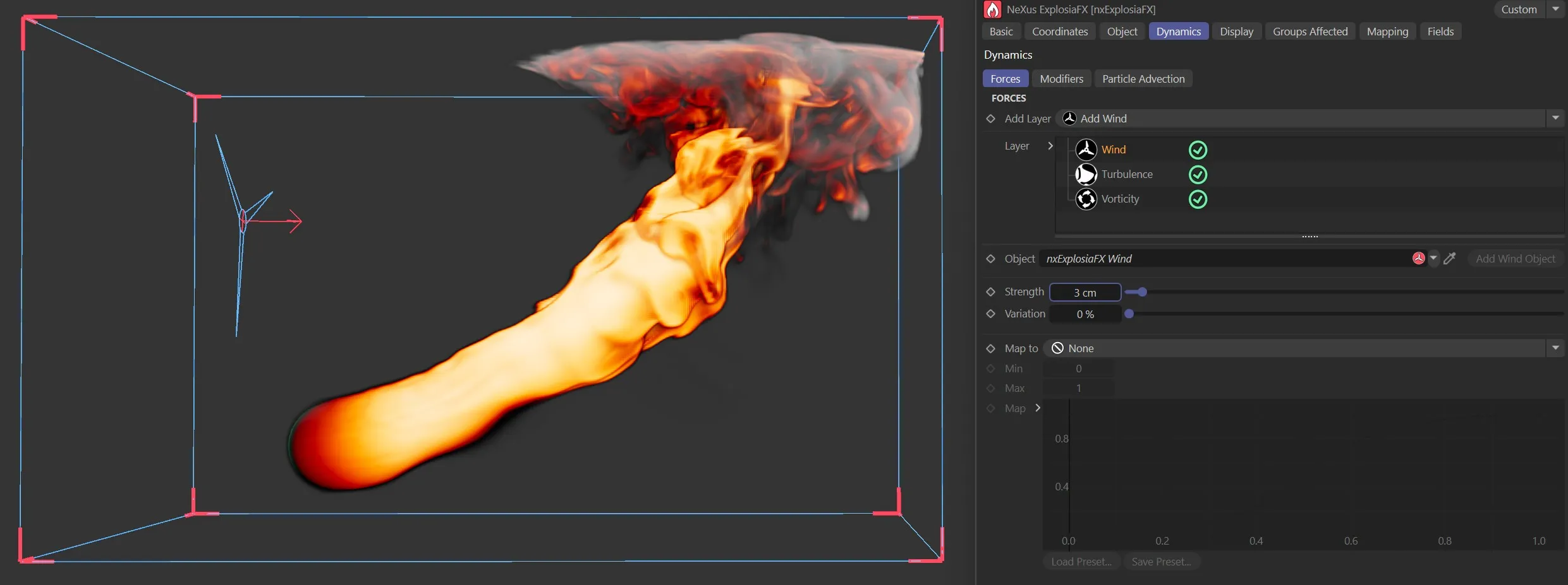
Wind object moving the simulation.
Strength
Section titled “Strength”Alters the wind strength.
Variation
Section titled “Variation”Adds a random variation level to the wind strength.
Map to, Min, Max, Map
Section titled “Map to, Min, Max, Map”These parameters offer the same mapping options as the ones in the Turbulence layer.
Modifiers subtab
Section titled “Modifiers subtab”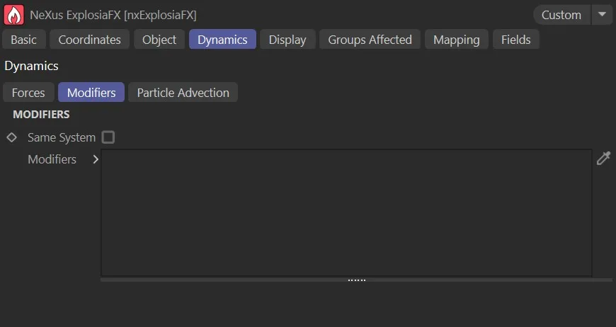
The Modifiers subtab options.
Same System
Section titled “Same System”If this box is checked, only objects which are child objects of the same System object as the solver will be used as sources.
This setting is ignored if the solver is not in a System object hierarchy.
Modifiers
Section titled “Modifiers”Drag the required modifiers into this list.
You can temporarily disable a modifier in the list by clicking the green check mark icon, to change it to a red cross.
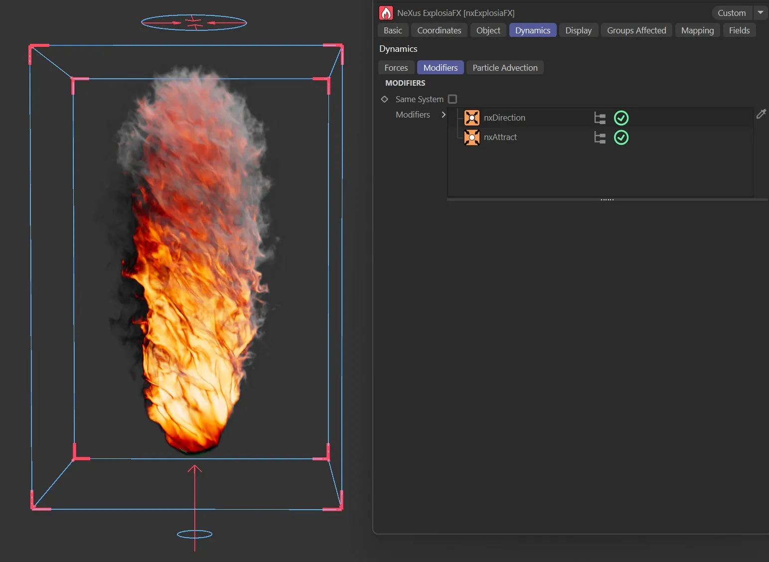
The Modifiers subtab simulation, using nxDirection and nxAttract modifiers.
Particle Advection subtab
Section titled “Particle Advection subtab”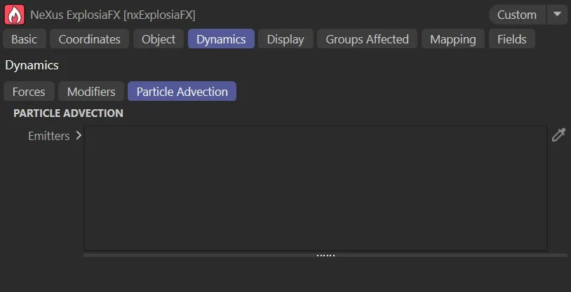
The Particle Advection subtab options.
Emitters
Section titled “Emitters”If you add an emitter to the scene, its particles will be carried along by the fluid’s velocity field, following the motion of the simulation.
Additional parameter options will become available once the emitter is dropped into the list.
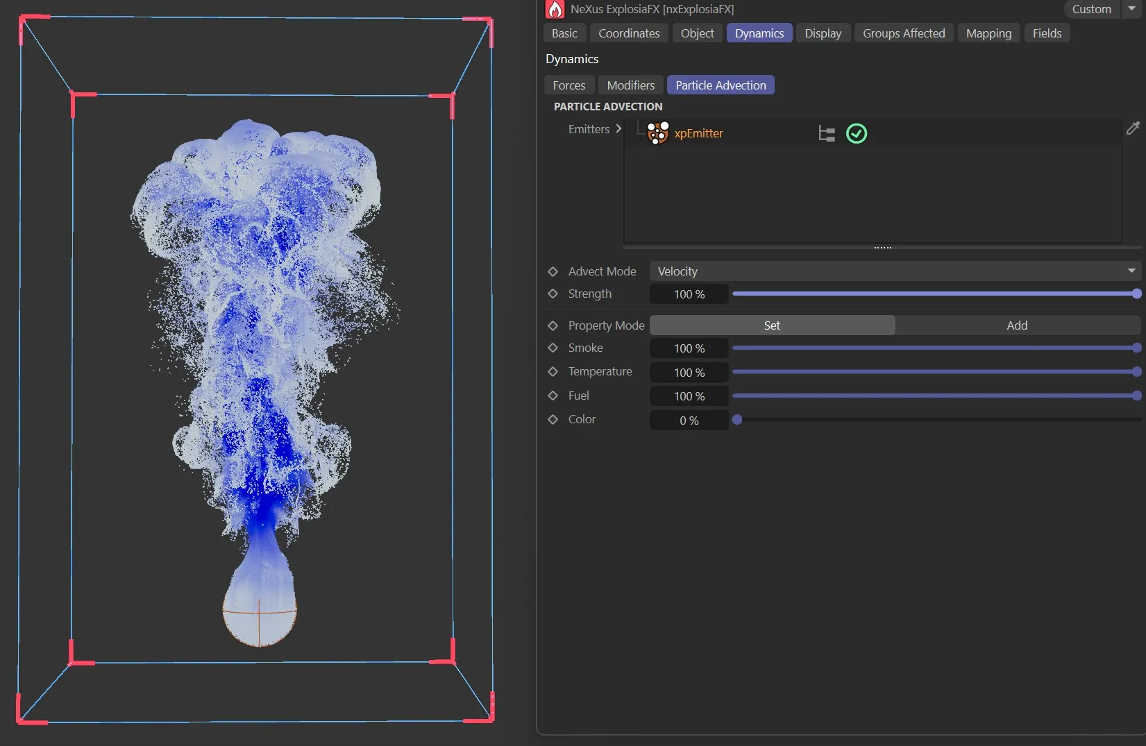
xpEmitter dropped into the Emitters list, being advected by the simulation.
Display tab
Section titled “Display tab”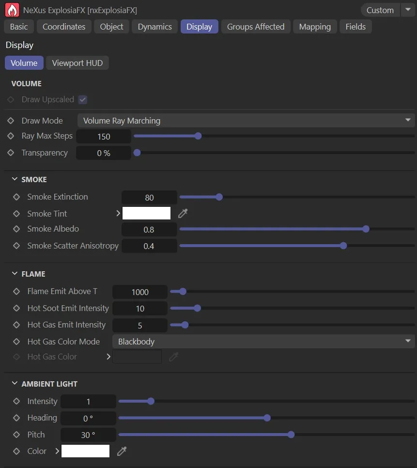
The Volume subtab UI in the Display tab.
Volume subtab
Section titled “Volume subtab”Draw Upscaled
Section titled “Draw Upscaled”With this enabled Upscaled simulations will be drawn in the viewport.
Draw Mode
Section titled “Draw Mode”Set as Volume Ray Marching, by default.
The other options are: Off or Volume Slicing.
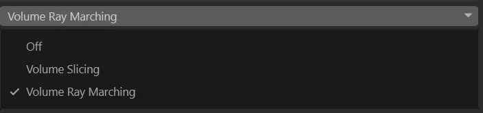
The Volume subtab Draw Mode setting options.
Disables all drawing in the viewport.
Volume Ray Marching mode options
Section titled “Volume Ray Marching mode options”This default setting gives the options below.
Ray Max Steps
Section titled “Ray Max Steps”Increases or decreases the quality of the volume ray marching, with the usual effects on viewport display and render times at higher values.
Transparency
Section titled “Transparency”Controls the levels of transparency in the solver, allowing the visualization of the smoke and fire to be made more or less transparent for tuning the visibility of other scene elements.
Smoke Extinction
Section titled “Smoke Extinction”Alters the rendering of the simulation, thickening or thinning the smoke appearance.
Smoke Tint
Section titled “Smoke Tint”Changes the color of the smoke with the usual C4D palette.
Smoke Albedo
Section titled “Smoke Albedo”This setting concerns the reflectiveness of the volume.
At higher levels, there is more light coloring in the smoke.
At lower levels, there is a more regular smokey color.
Smoke Scatter Anisotropy
Section titled “Smoke Scatter Anisotropy”The direction that light is scattered when it is within the volume, towards or away from the light-source.
Flame Emit Above T
Section titled “Flame Emit Above T”Sets the temperature above which flames are emitted.
Hot Soot Emit Intensity
Section titled “Hot Soot Emit Intensity”Controls the incandescent glow from hot soot particles within the flame. Higher values produce a brighter, more luminous glow; lower values reduce the glow.
Hot Gas Emit Intensity
Section titled “Hot Gas Emit Intensity”Controls the level of gas emitted, to give further controls over the flame appearance.
Hot Gas Color Mode
Section titled “Hot Gas Color Mode”Set as Blackbody, by default, this gives a realistic coloring, dependent on heat.
The other option is Manual, which engages the setting below for the color choice.
Hot Gas Color
Section titled “Hot Gas Color”Only becomes available once the Hot Gas Color Mode is set to Manual.
This then allows a color to be selected from the pallet.
Ambient Light
Section titled “Ambient Light”These options are for the ray marcher display and provide settings for a uniform ambient light that illuminates the EFX volume; basically illuminating the smoke from an external lamp.
Heading, Pitch
Section titled “Heading, Pitch”The ‘lamp’ shines from a particular direction, which is set using the two angles: Heading and Pitch.
Intensity
Section titled “Intensity”Sets the brightness of the ‘lamp’.
Sets the color of the ‘lamp’.
Volume Slicing mode options
Section titled “Volume Slicing mode options”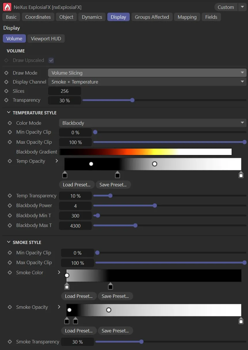
The Volume subtab, with Draw Mode set to Volume Slicing UI in the Display tab.
Changing the setting to Volume Slicing gives more options.
Display Channel
Section titled “Display Channel”This is set as Smoke + Temperature, by default.
The other options are: Smoke + Fuel, Temperature, Smoke, Fuel, Color or Speed.
Each of these will give different animations based on personal need in the scene and, again, will make different parameter options available, which can be manipulated to give the ‘look’ that you desire.
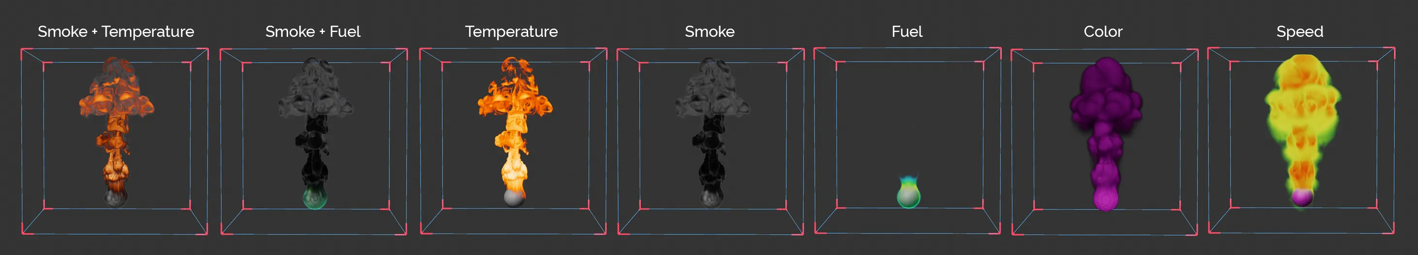
The Volume tab, slicing Display Channel setting options.
Slices
Section titled “Slices”More slices means more detail and a smoother visualization, but it can also reduce the performance of the viewport.
Transparency
Section titled “Transparency”Controls the levels of transparency in the solver, allowing the visualization of the smoke and fire to be made more or less transparent for tuning the visibility of other scene elements.
Viewport HUD subtab
Section titled “Viewport HUD subtab”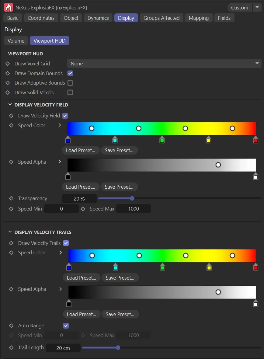
The Viewport HUD subtab options, with both Draw Velocity Field and Draw Velocity Trails checked.
Draw Voxel Grid
Section titled “Draw Voxel Grid”Set as None, by default, this menu controls how the voxel grid is (or isn’t) is displayed.
The alternative settings are: Full, Back only, Base only, Base and back and All back faces.
Draw Domain Bounds
Section titled “Draw Domain Bounds”On by default, this box can be unchecked to remove the domain bounds.
Draw Adaptive Bounds
Section titled “Draw Adaptive Bounds”This can be checked to display the bounds as they dynamically adapt to the solver.
Draw Solid Voxels
Section titled “Draw Solid Voxels”Enable this to show the voxels in the scene.
Display Velocity Field
Section titled “Display Velocity Field”Draw Velocity Field
Section titled “Draw Velocity Field”All options here are grayed out, by default.
Enabling this will give options to see the velocity field and provide access to the settings below.
Again, this is very memory-intensive.
Speed Color, Speed Alpha
Section titled “Speed Color, Speed Alpha”If this box is checked, the velocity color is taken from the Speed Color gradient, which appears.
Similarly for the alpha.
Transparency
Section titled “Transparency”The overall transparency of the display can be altered using this setting.
Speed Min, Speed Max
Section titled “Speed Min, Speed Max”Sets the minimum and maximum speeds of the velocity
Display Velocity Trails
Section titled “Display Velocity Trails”Draw Velocity Trails
Section titled “Draw Velocity Trails”Again, all options here are grayed out, by default.
Checking this box, will activate these settings and a trail is drawn to show changes in each voxel over time.
This gives you much more information about how temperature or other parameters are changing within the solver.
Speed Color/Speed Alpha
Section titled “Speed Color/Speed Alpha”If this box is checked, the velocity color is taken from the Speed Color gradient, which appears.
Similarly for the alpha.
Auto Range, Speed Min, Speed Max
Section titled “Auto Range, Speed Min, Speed Max”Checked by default, this can be disabled to allow more personal controls, using the Speed Min and Speed Max options.
Trail Length
Section titled “Trail Length”Increase or decrease length of the velocity trails (in scene units).
Groups Affected tab
Section titled “Groups Affected tab”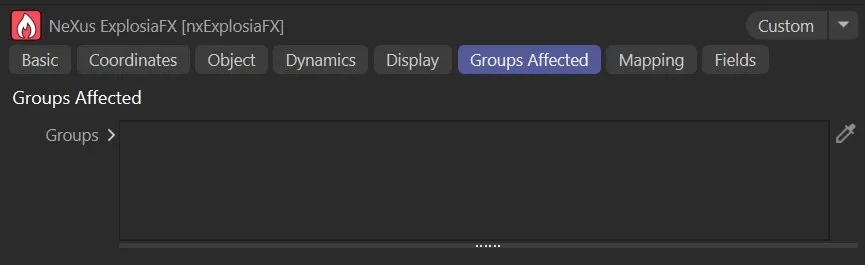
The Groups Affected subtab options.
Groups
Section titled “Groups”When a source object is an emitter, you can specify which groups are advected by dragging the particle group objects into this list.
If the list is empty, all groups emitted by the source emitter are advected.
Mapping tab
Section titled “Mapping tab”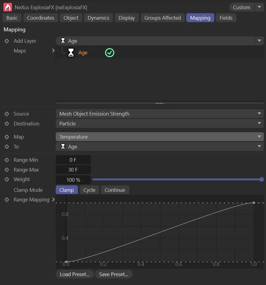
The Mapping tab options.
Add Layer
Section titled “Add Layer”The usual mapping layers are offered here.
List of the layers mapped in the scene.
For full details on how Mapping works, see the dedicated page:
Falloff tab
Section titled “Falloff tab”You can use the Fields options to control where nxExplosiaFX operates.