X-Particles Material
The X-Particles Material shader enables shading of the particles without any geometry.
If you want to render your particles and have them cast shadows, without using objects, then this offers the fastest and highest quality way to do so.
The X-Particles Material can also render splines without the need for geometry and has volumetric rendering for gas, smoke, fire, etc.
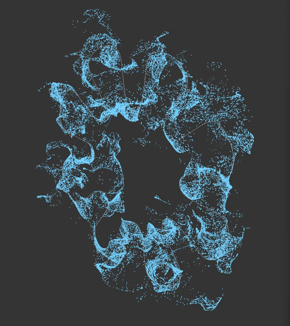
Viewport image, showing a particle simulation.
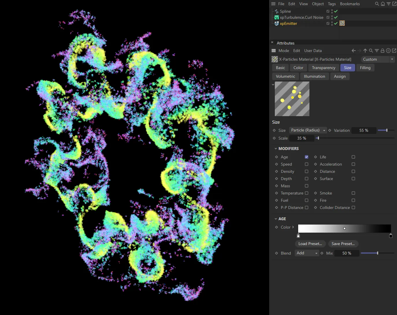
X-Particles Material added to the particles shown in the image on the left, with settings displayed above. A color gradient is mapped, dependent on particle speed, there are transparency and size modifications, based on particle age with the Age modifier enabled, the particle scale is reduced and variation is added.
To use this shader you should:
- create an X-Particles Material (you will find this in the Create->Shader menu of the material manager, or Create->Extensions menu in Cinema 4D)
- apply the material to an xpEmitter object or an X-Particles Group object
- add the X-Particles post-effect to the Cinema 4D render settings (normally done automatically when the material is created)
- play the animation and render the scene.
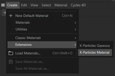
The X-Particles Material in the Materials Manager menu.
This lets you assign different materials to particles from the same emitter.
For example, if the emitter is emitting particles in two groups, you can assign one material to the first group and a different material to the second one.
To render a spline:
- create an xpEmitter and link an xpTrail object to it
- apply the X-Particles Material to the spline
- alternatively, create any spline including Cinema 4D spline primitives and apply the material to the spline
- render.
Basic tab
Section titled “Basic tab”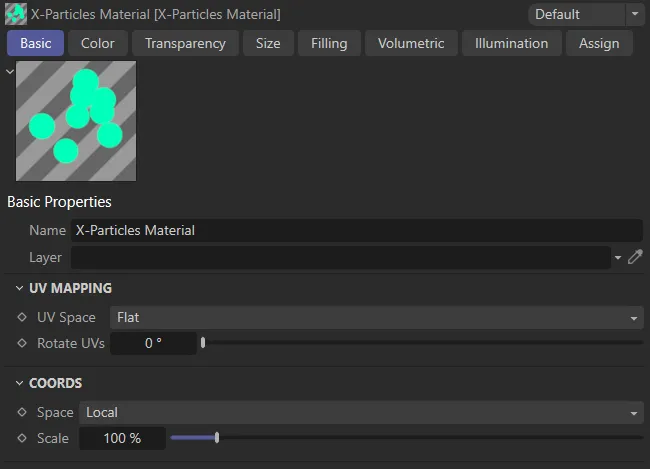
X-Particles Material, Basic tab menu settings.
Each particle, when rendered, can be given a set of UV coordinates, even though it is not an object.
You can change the UV space and rotate the UVs with these settings.
UV Mapping
Section titled “UV Mapping”UV Space
Section titled “UV Space”Set as Flat, by default, this drop-down assigns the UV space.
The other options are: Spherical and Tag.
A flat projection which, by default, will make the particle appear as a flat disk.
In this mode, any texture will always appear the same, no matter what the camera angle to the particle.
Spherical
Section titled “Spherical”A spherical projection which will make the particle appear as a Sphere.
In this mode, the appearance of any assigned texture will vary according to the camera angle to the particle (because if the angle changes, you will be looking at a different part of the Sphere).
The projection used is the one in the texture tag for the material when it is assigned to an emitter.
Rotate UVs
Section titled “Rotate UVs”This slider enables you to rotate the UVs.
The actual rotation for each particle is a random value between zero and the value in this slider.
The effect is that, if a texture is assigned to the particle, instead of each particle looking identical the texture is randomly rotated, making each particle look different.
Coords
Section titled “Coords”Set as Local, by default, this is the coordinate space used to sample shaders in the material.
The other options are: Particle, World, Screen and Camera.
Used to change the sampling coordinates by scaling them up or down.
Color tab
Section titled “Color tab”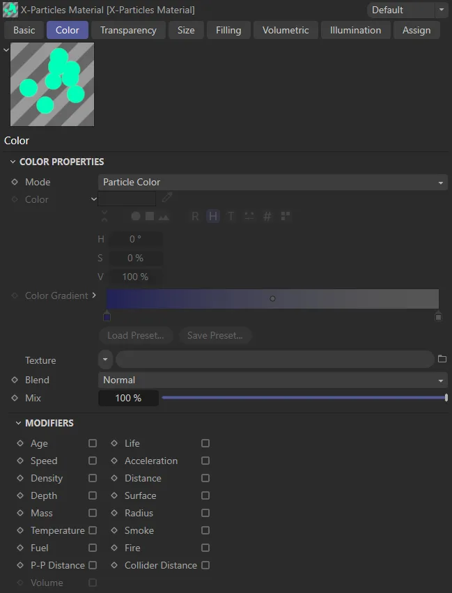
X-Particles Material, Color tab menu settings.
Set as Particle Color, by default, this drop-down menu has four settings.
Single Color
Section titled “Single Color”Particles are rendered with the color from the Color setting.
Random Color
Section titled “Random Color”The particles will each have a randomly-selected color.
Random (from Gradient)
Section titled “Random (from Gradient)”This option will enable the Color gradient and will randomly color the particles using a color taken from the gradient.
Particle Color
Section titled “Particle Color”The particle color is used.
This is useful, for example, if you have particles emitted from an object which are picking up their color from the object’s texture.
The color used in the Single Color mode.
Color Gradient
Section titled “Color Gradient”The gradient used in the Random (from Gradient) mode.
It is unavailable in other modes.
Texture
Section titled “Texture”In any mode, a shader or bitmap can be placed into this link and the particles will then be rendered with that shader (or bitmap).
With this setting, X-Particles can be used as a true placard renderer, without the need for any additional geometry.
Alpha textures can also be used by adding them to Texture field in the Transparency tab.
Each particle has its own UV coordinates; in the Basic tab (found in the Attributes Manager), you can define the UV space used and an option to add random rotation to the particle UVs.
Set as Normal, by default, these are four blend modes to blend the color from the Texture link with the color from the Mode drop-down.
The other options are: Multiply, Add and Subtract.
The percentage mixture of the Texture color and color from Mode.
A Mix of 100% is entirely the Texture color.
A Mix of 0 (zero) % is entirely from the Mode setting.
Modifiers
Section titled “Modifiers”In addition, there are a series of modifiers, which will alter the color, depending on certain particle parameters.
When one of these boxes is checked, additional controls are displayed.
The modifiers available are:
The age of the particle - younger particles have the color on the left of the gradient.
Particle speed.
Density
Section titled “Density”The particle density.
The depth of field.
The particle mass setting.
Temperature
Section titled “Temperature”The particle temperature setting.
The particle fuel value.
P-P Distance
Section titled “P-P Distance”The distance between a particle and its nearest neighbor.
Volume
Section titled “Volume”The radius, density or transparency of a volumetric particle.
The lifespan of the particle.
Acceleration
Section titled “Acceleration”The particle’s acceleration.
Distance
Section titled “Distance”The distance of the particle from the camera.
Surface
Section titled “Surface”The particle color is taken from the surface from which it is emitted.
Radius
Section titled “Radius”The particle radius setting.
The particle smoke density.
The particle burn value.
Collider Distance
Section titled “Collider Distance”The minimum distance from the particle to a collider object.
Most of these are all very similar, a typical set are the Speed controls, below.
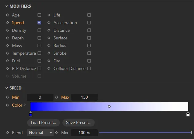
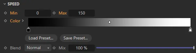
Speed modifier, menu settings.
Min, Max
Section titled “Min, Max”The range of values the shader will use to get the particle color from the gradient.
The Color gradient shows the range of colors of the rendered particles.
The actual color depends on the Min and Max settings.
In this case, particles with a speed of zero would be coloured blue, those with a speed of 150 or more would be white.
Speeds between those values would result in intermediate colors.
Blend, Mix
Section titled “Blend, Mix”The Blend setting enables you to blend between colors from the modifier gradient and the Color setting.
A Mix of 100% means that only the gradient is used to determine the color.
A Mix of 0 (zero) % means that only the Color setting is used.
Blend gives the mode used to blend the colors.
The Surface modifier is slightly different from the other options.
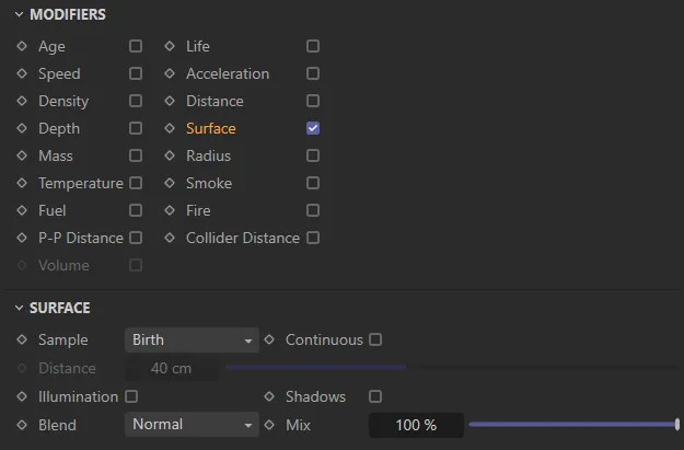
Surface modifier, menu settings.
Sample
Section titled “Sample”Set as Birth, by default, this drop-down defines when the sampling of the surface should take place.
The alternative settings are: Group Change, Collision and Distance.
When the particle is created.
Group Change
Section titled “Group Change”When the particle’s group is changed.
Collision
Section titled “Collision”When a collision occurs.
Distance
Section titled “Distance”When the particle has travelled the distance in the Distance setting.
Continuous
Section titled “Continuous”If checked, the original sampling position (on the emitting object) is sampled for every frame rendered so, if the texture/surface is changing, the particle color will also change.
Distance
Section titled “Distance”The distance used when Sample is set to Distance.
Illumination
Section titled “Illumination”If checked, the particle is self-illuminating.
Shadows
Section titled “Shadows”If checked, illuminated particles are self-shadowing.
Blend, Mix
Section titled “Blend, Mix”The Blend setting enables you to blend between colors from the modifier and the Color setting.
A Mix of 100% means that only the modifier is used to determine the color.
A Mix of 0 (zero) % means that only the Color setting is used.
Blend gives the mode used to blend the colors.
The other modifier which is different from the other options is the Volume modifier.
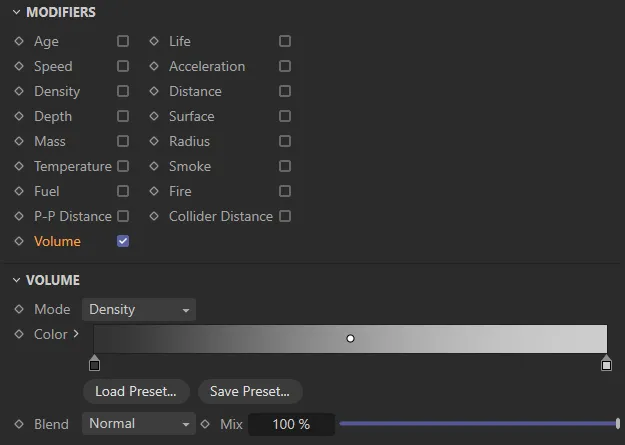
Volume modifier, menu settings.
Set as Density, by default, this determines the value of the volumetric particle which affects the color.
The alternatives are: Radius and Transparency.
The color gradient to blend with the particle color.
Blend, Mix
Section titled “Blend, Mix”The Blend setting enables you to blend between colors from the modifier gradient and the Color setting.
A Mix of 100% means that only the gradient is used to determine the color.
A Mix of 0 (zero) % means that only the Color setting is used.
Blend gives the mode used to blend the colors.
Transparency tab
Section titled “Transparency tab”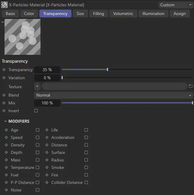
X-Particles Material, Transparency tab menu settings.
Use this tab to set the opacity of the rendered particles.
Transparency
Section titled “Transparency”This sets the transparency of the rendered particles.
A setting of 0 (zero) % means no transparency (fully opaque).
Variation
Section titled “Variation”This setting enables some variation to be added to the Transparency value.
Texture
Section titled “Texture”If a shader or bitmap is added to this link, it will be used to determine the transparency.
This can act as an alpha map to cut out parts of the rendered particle.
Each particle has its own UV coordinates, in the Basic tab (found in the Attributes Manager).
You can define the UV space used and an option to add random rotation to the particle UVs.
Four blend modes to blend the value from the Texture link with the value from the Transparency field.
The percentage mixture of the Texture value and the value from Transparency.
A mix of 100% is entirely the Texture value and a mix of 0 (zero) % is entirely from the Transparency setting.
Invert
Section titled “Invert”If checked, inverts the transparency (so black becomes fully opaque rather than fully transparent).
Modifiers
Section titled “Modifiers”These are the same modifiers as in the Color tab.
The displayed settings differ slightly from the color settings, here is the Speed modifier set.
Speed modifier, menu settings.
The only difference is that the gradients use a greyscale value where black is fully opaque (zero transparency) and white is 100% transparent.
The Transparency tab has an extra modifier, Noise.
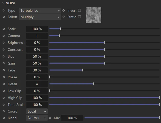
Noise modifier, menu settings.
This enables you to add noise to the transparency.
The noise type, as seen in the Cinema 4D, Noise shader.
Invert
Section titled “Invert”Inverts the noise sample.
Falloff
Section titled “Falloff”Set as Multiply, by default, the method by which the noise from individual particles is blended.
Multiply
Section titled “Multiply”The greyscale values are multiplied.
No blending.
Subtract
Section titled “Subtract”The greyscale values are subtracted from one another.
Static
Section titled “Static”If this box is checked, the noise will not be affected by time, otherwise it will change as time passes (if the noise Type supports that).
Scales the noise effect up and down.
Alters the gamma value of the noise.
Brightness, Contrast
Section titled “Brightness, Contrast”These are the same parameters as found in the standard Cinema 4D Noise shader.
Please refer to the Cinema 4D Help files for details.
Controls the noise intensity.
Lowering it, shifts the level through the noise value to make the noise more prominent.
Increasing it, flattens out the noise, making it less noisy.
As with Bias, this can be used to affect the noise intensity.
This setting softens the noise so it fades out further from the particle.
Increasing this value will move the noise with time, rather like an offset.
Detail
Section titled “Detail”This is the noise detail, that is, the number of octaves the noise is built from.
Low Clip, High Clip
Section titled “Low Clip, High Clip”Low and high clipping values, as in the Cinema 4D, Noise shader.
Time Scale
Section titled “Time Scale”This will scale the document time to speed up or slow down animated noise (assuming Static is not checked).
The coordinate space used to create the noise.
If set to Default, the coordinates are taken from the Basic tab.
Blend, Mix
Section titled “Blend, Mix”The Blend setting enables you to blend between colors, from the noise and the particle color.
A Mix of 100% means that only the noise is used to determine the color.
A Mix of 0 (zero) % means that only the particle color is used.
Blend gives the mode used to blend the colors.
Size tab
Section titled “Size tab”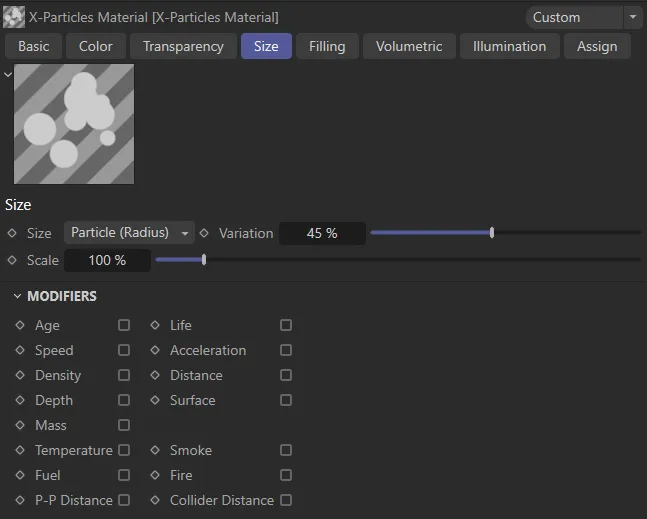
X-Particles Material, Size tab menu settings.
Set as Particle (Radius), by default, this drop-down menu determines the size of the rendered particles.
The other options are: World and Screen.
Particle (Radius)
Section titled “Particle (Radius)”The particle radius determines the rendered size.
A custom size is set in the Custom parameter.
In this mode, particles which are farther from the camera are rendered smaller than those close to the camera.
Screen
Section titled “Screen”A custom size is set in the Custom parameter.
In this mode, all particles are rendered the same size regardless of distance from the camera.
Variation
Section titled “Variation”Regardless of the Size mode, this setting is used to add variation to the size of the rendered particles.
Regardless of the Size mode, this setting is used to scale the size of the rendered particles up or down.
Modifiers
Section titled “Modifiers”The same modifiers as in the Color tab, with the exception of the Radius modifier, which is not relevant in this tab.
Filling tab
Section titled “Filling tab”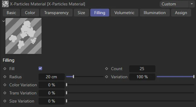
X-Particles Material, Filling tab menu settings.
This tab is used to add additional particles (‘fill particles’) at render time only.
It is a simple way to add very large numbers of extra particles when rendering without actually generating and maintaining the additional particles.
The size of the fill particles will be the same as the corresponding ‘real’ particle, subject to the Size Variation setting, below.
Check this box to add fill particles.
The number of fill particles to add for each ‘real’ particle.
Radius, Variation
Section titled “Radius, Variation”This is not the size of the fill particle, but the size of an imaginary Sphere around each real particle in which the fill particles will be rendered.
Color Variation
Section titled “Color Variation”The fill particles will have the same color as their ‘real’ particle, but this setting can be used to add color variation to the fill particles.
Trans Variation
Section titled “Trans Variation”The fill particles will have the same transparency as their ‘real’ particle, but this setting can be used to add transparency variation to the fill particles.
Size Variation
Section titled “Size Variation”The fill particles will have the same size as their ‘real’ particle, but this setting can be used to add size variation to the fill particles.
Volumetric tab
Section titled “Volumetric tab”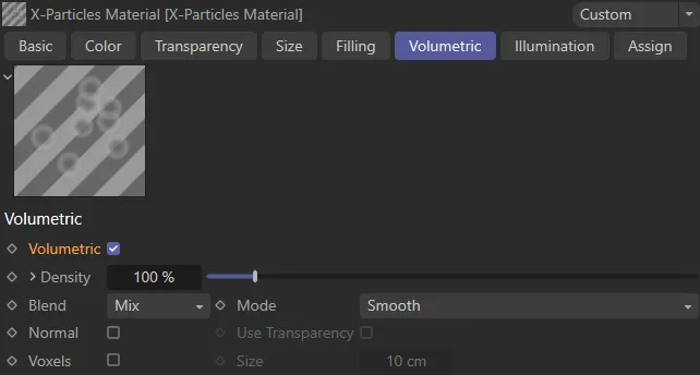
X-Particles Material, Volumetric tab menu settings.
This tab controls the volumetric rendering of particles.
To understand these settings, it is important to understand what the material is doing in volumetric mode.
Each ray cast by Cinema 4D at render time is sampled at points along the ray (which are determined by the X-Particles render settings) through any volumetric particles hit.
Volumetric
Section titled “Volumetric”Check this box to enable volumetric rendering.
Density
Section titled “Density”The lower this is, the more transparent the volume particle is.
Each particle combines to increase the opacity of each sample point going through the volume.
Click the small arrow to the left of the parameter to reveal the Falloff spline.
Falloff
Section titled “Falloff”The spline controls the density falloff from the center of the particle’s volume (which is Spherical).
Set as Mix, by default, the ray may hit multiple particles in the scene and this drop-down controls how the particle density volumes are blended together.
The other options are: Isosurface, Weighted and Absolute.
This option treats each volume as its own density with the first hit occluding any further along the ray.
Isosurface
Section titled “Isosurface”Here, the density is clipped at the Iso Level, to give a skinner like rendering, rendering the isosurface of the particle volume.
Weighted
Section titled “Weighted”The blending is based on distance weighting from the particle.
Absolute
Section titled “Absolute”The maximum density of overlapping volumes is used.
Iso Level
Section titled “Iso Level”This is only available if Blend is set to Isosurface.
Once the Blend is selected, the curve used to blend the density values can be changed here.
To use a custom curve select Custom and modify the spline in the Curve setting.
The options available are: Smooth, Cube, Blinn (Blobbies), Wyvill, Links, RenderMan, Hart, Geiss and Custom.
Normal
Section titled “Normal”When checked, the material calculates a normal based on the density value.
This is used with the illumination modes Diffuse and Phong and is mainly useful when Blend is set to Isosurface.
Use Transparency
Section titled “Use Transparency”Only available if Normal is checked.
When checked, transparency (e.g. noise) will be included in the normal calculation.
Voxels
Section titled “Voxels”When checked, rather than rendering each particle as a volume, it combines them into voxels (the size of which is set with the Size parameter), to give a voxel-based volumetric render.
The voxel size if Voxels is checked.
Illumination tab
Section titled “Illumination tab”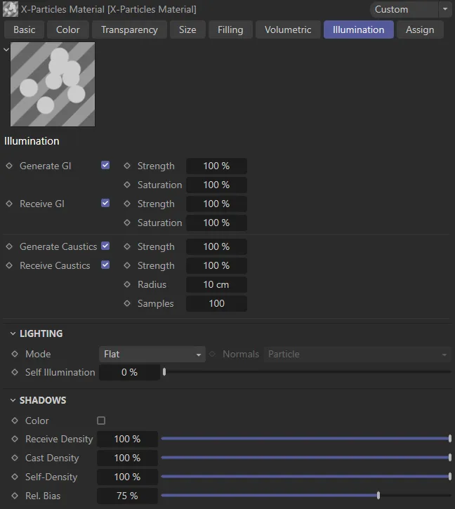
X-Particles Material, Illumination tab menu settings.
Generate GI
Section titled “Generate GI”If Global Illumination is active in the Cinema 4D render settings, checking this box will enable illumintated particles to contribute to the overall scene lighting.
Receive GI
Section titled “Receive GI”If Global illumination is active in the CInema 4D render settings, particles will be illuminated by any other scene object emitting light.
Generate Caustics
Section titled “Generate Caustics”If Caustics is active in the Cinema 4D render settings, checking this box will enable particles to generate caustics.
Receive Caustics
Section titled “Receive Caustics”If Caustics is active in the CInema 4D render settings, caustics created by scene objects can be cast on particles.
Lighting
Section titled “Lighting”Set as Flat, by default, the style of rendered particle.
The other options are: Phong, Diffuse, Fuzzy, Neon and Henyey-Greenstein, Schlick and Rayleigh.
Basic, flat shading.
Standard phong shading with specular settings.
Diffuse
Section titled “Diffuse”Renders as shaded Spheres, rather than discs.
Produces soft, fuzzy-edged particles.
Particles have a surrounding glow.
Henyey-Greenstein, Schlick and Rayleigh
Section titled “Henyey-Greenstein, Schlick and Rayleigh”These are all scattering illumination models, with each giving a different look.
It is suggested the user try each and select the one giving the desired effect.
These modes and their settings repay experimentation as it is difficult to describe the different effects of each.
Various parameters will become available depending on the selected style.
Normals
Section titled “Normals”The Diffuse and Phong illumination models require a normal to be provided.
This drop-down lets you select the source of the normal from: Particle, Velocity, X Axis, Y Axis, Z Axis and Light.
Self Illumination
Section titled “Self Illumination”The amount of self-illumination of the particles can be increased with this control.
It has a greater effect in some models (e.g. Phong) than in others.
Diffuse
Section titled “Diffuse”The amount of color diffusion.
Only available for Diffuse and Phong models; reducing this value will result in flatter color shading.
Specular, Width
Section titled “Specular, Width”Only available in the Phong model; these parameters control the brightness (‘Specular’) and size (‘Width’) of the specular highlight.
Width, Falloff Spline
Section titled “Width, Falloff Spline”Only available in the Fuzzy model; these parameters control the fuzziness of the rendered particle.
Width, Falloff
Section titled “Width, Falloff”Only available in the Neon model; they control the size and falloff of the effect.
Eccentricity
Section titled “Eccentricity”Only available in the Henyey-Greenstein and Schlick models.
These are scattering illumination models and this setting controls the strength of the scattering.
Shadows
Section titled “Shadows”If checked, this setting enables colored shadows (from the lights).
Receive Density
Section titled “Receive Density”As in the Cinema 4D lights, this is the density (strength) of shadows from geometry in the scene cast onto the particles.
Cast Density
Section titled “Cast Density”Alters the density of the shadow cast by the particles.
A value of zero results in no shadows.
Self-Density
Section titled “Self-Density”This is the density of shadows received by particles from other particles.
Rel Bias
Section titled “Rel Bias”This setting helps to keep the shadows from self-shadowing (so a particle doesn’t shadow itself).
The setting is a percentage of the particles radius.
Copyright © 2026 INSYDIUM LTD. All rights reserved.