X-Particles Gaseous
This shader is used to render fire and smoke when using X-Particles.
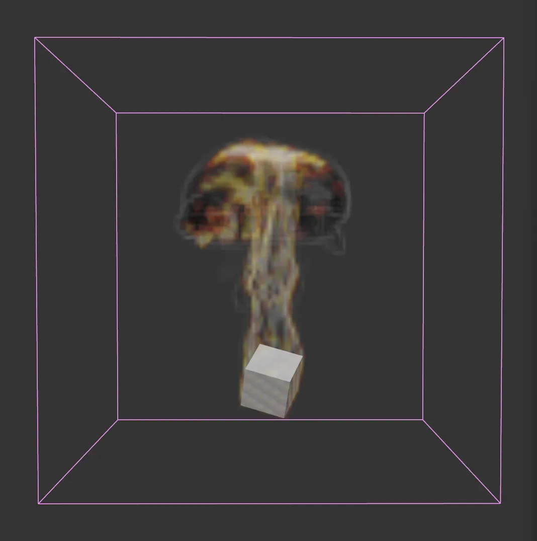
Viewport image, showing an xpExplosiaFX simulation.
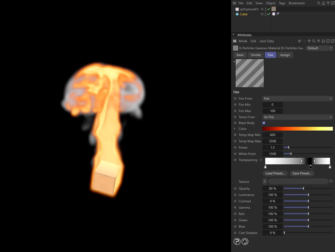
X-Particles Gaseous shader has been added to the fire and smoke sim in the image on the left, with settings displayed above.
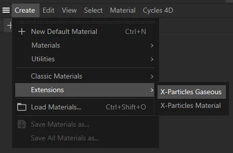
The X-Particles Gaseous option is in the Create tab, under Extensions.
Basic tab
Section titled “Basic tab”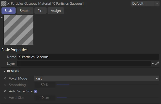
X-Particles Gaseous, Basic tab menu settings.
The name of the material.
The Cinema 4D layer (group of scene items that are being controlled together).
Render
Section titled “Render”Voxel Mode
Section titled “Voxel Mode”Set as Fast, by default, this drop-down governs how the voxels in the simulation are rendered.
The other options are: Smoothed and Custom.
The voxels are rendered without any smoothing.
Smoothed
Section titled “Smoothed”A fixed smoothing amount is applied to the voxels.
Custom
Section titled “Custom”With this option you can apply a custom amount of smoothing using the Smoothing parameter.
Smoothing
Section titled “Smoothing”The amount of smoothing to apply when Voxel Mode is set to Custom.
Auto Voxel Size
Section titled “Auto Voxel Size”If this box is checked, the voxel size is taken from the Domain object, if the material is applied to a domain.
If it is applied to an emitter, the voxel size is the radius setting in the emitter, multiplied by 2.
If applied to an emitter it is recommended that this setting is unchecked and a custom size set in Voxel Size.
Voxel Size
Section titled “Voxel Size”The voxel size used for rendering, if Auto Voxel Size is unchecked.
Smoke tab
Section titled “Smoke tab”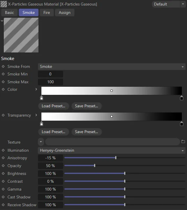
X-Particles Gaseous, Smoke tab menu settings.
Smoke From
Section titled “Smoke From”Set as Smoke, by default, this drop-down enables you to select where the smoke values are taken from.
You can take the smoke values from any of the physical properties.
The other options available are: None, Temperature, Fire and Fuel.
Smoke Min, Smoke Max
Section titled “Smoke Min, Smoke Max”The smoke values are mapped to the Color and Transparency gradients so that values at, or less than, the minimum are given the color from the gradient’s left edge while values at, or higher than, the maximum are given the color from the gradient’s right edge.
The color of the smoke, mapped from the smoke value.
Transparency
Section titled “Transparency”The transparency of the smoke, mapped from the smoke value.
Texture
Section titled “Texture”A texture such as a Noise shader can be applied to the smoke values from UV coordinates generated by the domain simulation.
This helps to give more details into lower resolution simulations.
Illumination
Section titled “Illumination”This is the illumination model used.
Isotropic illuminates the smoke irrelevant of light and view direction.
The other models all change the illumination based on light and view direction.
Clouds/smoke tend to be darker when the light source is behind them (the light is scattered); when the light is in front and reflecting they are brighter.
The different models (Henyey-Greenstein, Double Henyey-Greenstein, Schlick and Rayleigh, as well as the Anisotropy option) enable you to change how they appear.
Anisotropy
Section titled “Anisotropy”This option changes whether the smoke is darker with the light behind or in front.
Back Scattering
Section titled “Back Scattering”Only available in the Double Henyey-Greenstein illumination model.
It also changes the illumination in combination with Anisotropy to simulate the scattering of light.
These are best tried to see their effect with a light source.
Opacity
Section titled “Opacity”This controls how opaque the smoke is, lower for wispy smoke and higher for thick dark smoke.
Brightness, Contrast, Gamma
Section titled “Brightness, Contrast, Gamma”These are the common controls over the color.
They help with tweaking the colors of the simulation, rather than having to make many small changes to the gradients.
Cast Shadow
Section titled “Cast Shadow”This controls the opacity of the shadow cast by the smoke.
Higher values represent greater opacity.
Receive Shadow
Section titled “Receive Shadow”This controls the opacity of any shadows falling on the smoke.
Higher values represent greater opacity.
Fire tab
Section titled “Fire tab”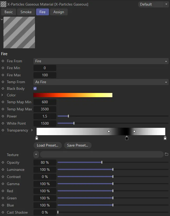
X-Particles Gaseous, Fire tab menu settings.
Fire From
Section titled “Fire From”This drop-down enables you to select where the fire values are taken from.
By default this is Fire, but you can take the fire values from any of the physical properties.
The other options are: None, Temperature, Smoke and Fuel.
Fire Min, Fire Max
Section titled “Fire Min, Fire Max”The fire values are mapped to the Color and Transparency gradients so that values at or less than the minimum are given the color from the gradient’s left edge,
Values at, or higher than, the maximum, are given the color from the gradient’s right edge.
Temp From
Section titled “Temp From”This drop-down enables you to select where the temperature values are taken from.
By default this is As Fire, but you can take the temperature values from any of the physical properties.
The other options are: None, Temperature, Smoke, Fire and Fuel.
Black Body
Section titled “Black Body”If this box is checked, the fire colors use a physically-based black body color, and cannot be edited.
If it is unchecked, the colors in the Color gradient can be altered as desired.
The color of the fire, mapped from the fire value (see Fire Min and Fire Max, above).
Clicking the drop-down arrow, next to Color will reveal the Mapping parameter.
Mapping
Section titled “Mapping”This drop-down will map the colors to a variety of different color spaces, depending on the desired output.
For example, if displaying the result on a PAL device you would choose PAL in the drop-down.
The list has six options: NTSC, PAL, SMPTE, HDTV, CIE and CIE REC 790.
Temp Map Min, Temp Map Max
Section titled “Temp Map Min, Temp Map Max”The temperature values are mapped to the Color gradient so that values at or less than the minimum are given the color from the gradient’s left edge.
Values at, or higher than, the maximum, are given the color from the gradient’s right edge.
This setting controls the power used for black body illumination.
The physically correct value is 4, but this produces such a large range it is not easily used when rendering.
Lower values reduce the power and are therefore more manageable when rendered.
White Point
Section titled “White Point”Fire produces a huge dynamic range of colors.
This setting lets you change where the white point is in that range, making the colors easier to manage.
Transparency
Section titled “Transparency”The transparency of the fire, mapped from the fire value (see Fire Min and Fire Max, above).
Texture
Section titled “Texture”A texture such as a Noise shader can be applied to the fire values from UV coordinates generated by the domain simulation.
This helps to give more details into lower resolution simulations.
Opacity
Section titled “Opacity”Increasing this value will make the fire more opaque.
Luminance
Section titled “Luminance”This setting is used to control the dynamic range needed for fire, either to reduce it or boost it.
Contrast, Gamma
Section titled “Contrast, Gamma”These are the common controls over the color.
They help with tweaking the colors of the simulation rather than having to make many small changes to the gradients.
Red, Green, Blue
Section titled “Red, Green, Blue”You can use these settings to boost these color components, for example to give a redder fire.
This saves having to constantly tweak the gradient.
Cast Shadow
Section titled “Cast Shadow”A value above zero enables the fire to cast a shadow.
Generally flames don’t cast a shadow unless under very bright external light sources or if the light source is absorbed by the flame.
Copyright © 2026 INSYDIUM LTD. All rights reserved.