xpVertexMap
xpVertexMap enables you to generate customised, animated vertex maps on any scene object.
Vertex weight can be applied using particles, shaders, object vertices and more.
xpVertexMap User Interface (UI).
Objects
Section titled “Objects”Drag an object into this list.
You can add multiple objects, if you wish.
When an object is dropped into the list, it will automatically receive a vertex map tag, using the name in the Vertex Map Name parameter.
In addition, a layer is added to the object and that layer appears in this list.
Once the layer is selected, its options become available.
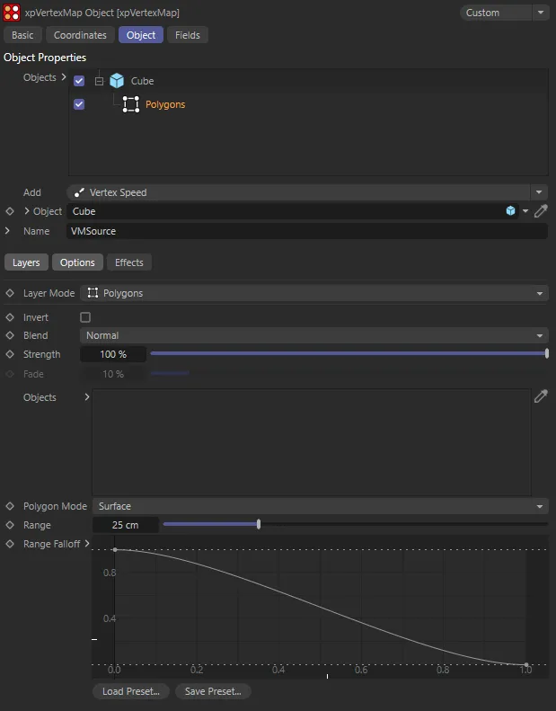
Here, a simple Cube primitive has been dropped into the Objects list, changing the UI.
In the image above, you can see that the layer - which by default is a Polygons layer - is selected and there are three tabs, Layers, Options and Effects, of which, the first two are selected and visible.
You can temporarily deactivate any object or layer in the list by unchecking the checkbox to the left of the name.
To delete a layer (or an object, with all its layers), select it and press the Delete key.
Alternatively, right-click the object or layer and choose Remove or Remove All from the context menu.
If you delete a layer, there may be none remaining for the object.
Simply select the object and choose a new layer from the Add menu button.
You can also reorder the layers by dragging them above or below other layers and, for blending purposes, the layer order is important.
This menu button enables you to add new layers to the object, which are blended with the layers below it if they are on the same object.
The layer options are: ExplosiaFX, Seed Object, Seed Map, Polygons, Splines, Texture, Vertex Speed, X-Particles/Vertices, Curvature and Ambient Occlusion.
Each one of these layer options comes with its own parameter options.
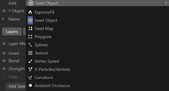
The Add menu options.
Object
Section titled “Object”This is the currently-selected object or the object to which the currently-selected layer is attached.
It is a link field, so you can drag a different object into this field and it will replace the object in the Objects list.
Objects can be editable polygon objects, primitive objects, generators such as Extrude, etc, and splines.
Clicking on the down arrow next to the Object parameter will reveal further Object Properties options, dependent on the layer object.
This is the name of the vertex map tag that will be created.
If you change it, the name of the tag on the object will be updated automatically.
The default name is VMSource.
You cannot delete the vertex map tag once created, it will be recreated automatically.
If you really need to delete the tag, turn the xpVertexMap object off in the Objects Manager and then delete the tag.
If you click the down-arrow, next to the Name parameter, there are additional options available.
Add Vertex Color Tag
Section titled “Add Vertex Color Tag”Enable this to add a vertex color tag as well as a vertex map tag.
This will also enable the following two options.
Add Vertex Color Tag is enabled on both of these images. The left-hand image is in the Polygon Mode of Surface.
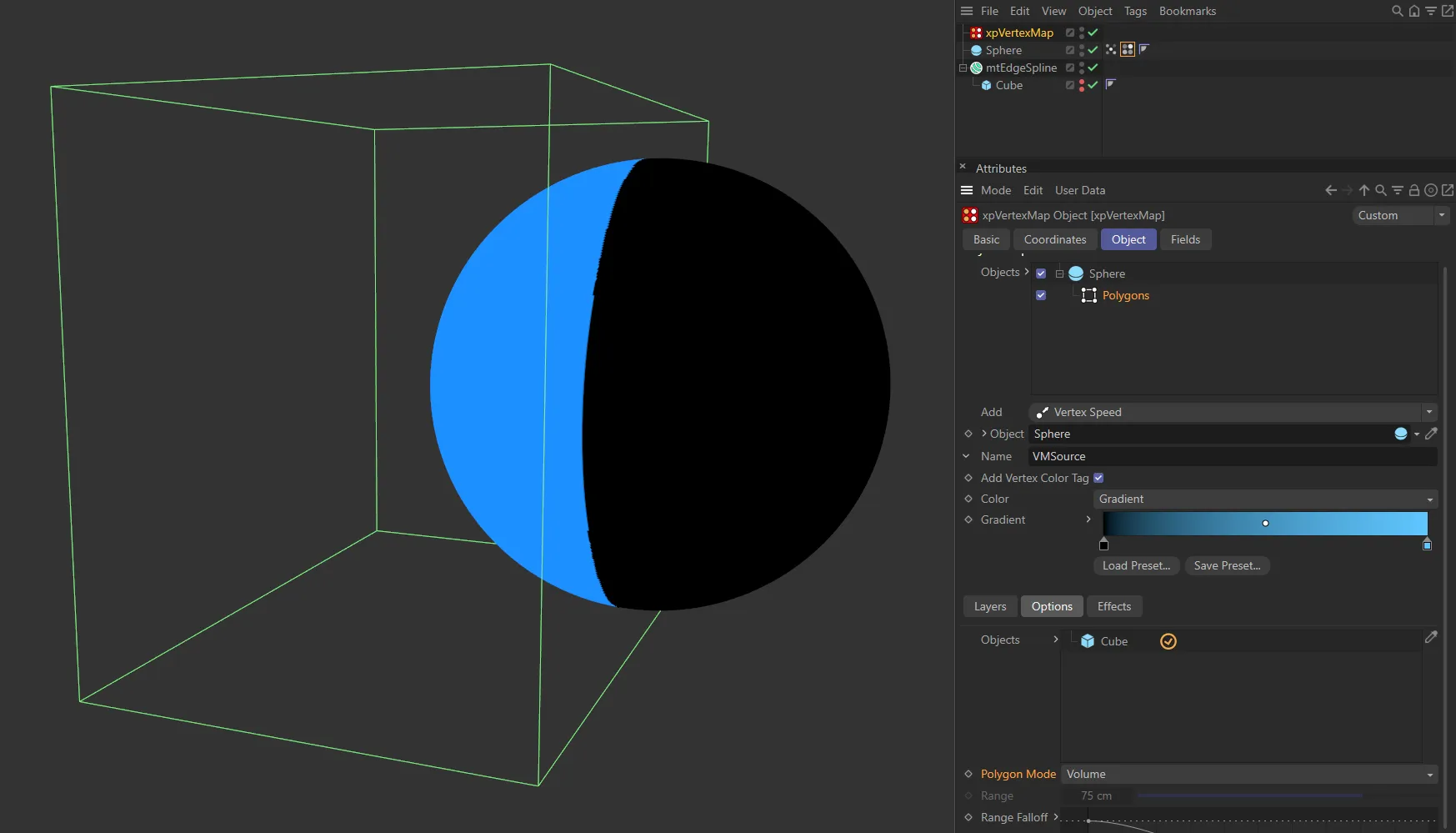
In this image, the Polygon Mode is Volume. Note: When using this mode, ensure there is a black knot on the left most side of the gradient and a knot of any color on the right, to achieve the appropriate result.
Set as Gradient, by default, this is the color mode for the tag.
The other option is Source.
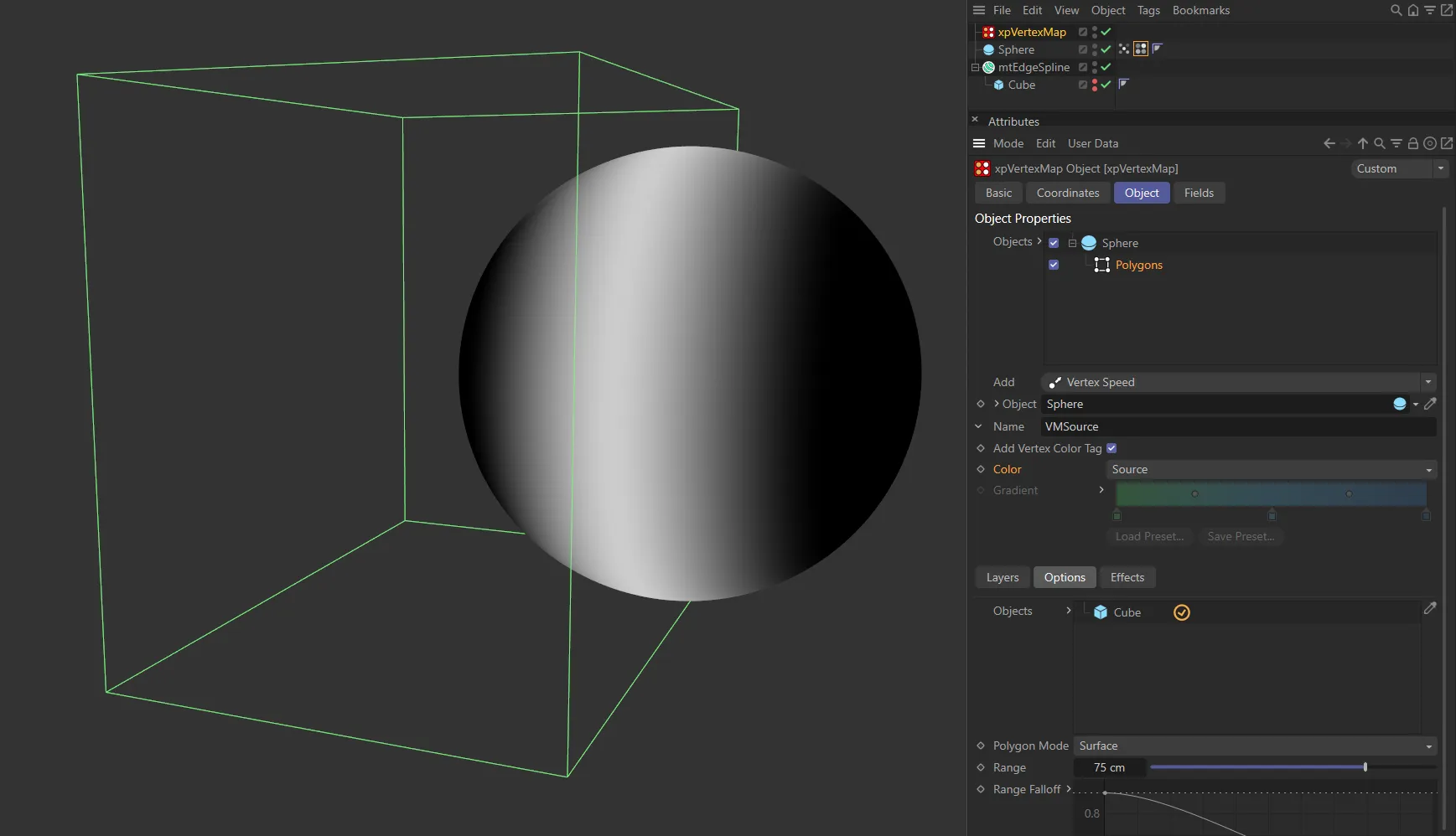
In this image, with the Color mode set as Source, the Vertex Color Tag generates a greyscale color map.
Gradient
Section titled “Gradient”The vertex colors are obtained from the Gradient setting.
The vertex weight determines the position along the gradient from which the color is selected.
Source
Section titled “Source”Colors are obtained from the source used to generate the vertex map.
For example, if an xpEmitter is used, the colors in the map are the particle colors.
If you use a Polygons layer, the colors are taken from the object color of the object(s) used to generate the vertex map.
Gradient
Section titled “Gradient”The gradient to use if Color Mode is set to Gradient.
Layers tab
Section titled “Layers tab”The settings in this section are common to all layers regardless of type, except for the Fade parameter.
Layer Mode
Section titled “Layer Mode”This menu is the same as the Add menu below the Objects list.
It enables you to change from one type of layer to another without having to delete the layer and add a new one.
Invert
Section titled “Invert”If enabled, the result generated by this layer is inverted.
Set as Normal, by default, this is a powerful option which lets you blend layers together.
The other options are: Min, Subtract, Multiply, Max, Add, Screen and Fade then Add.
Each layer is blended with the one below it in the list.
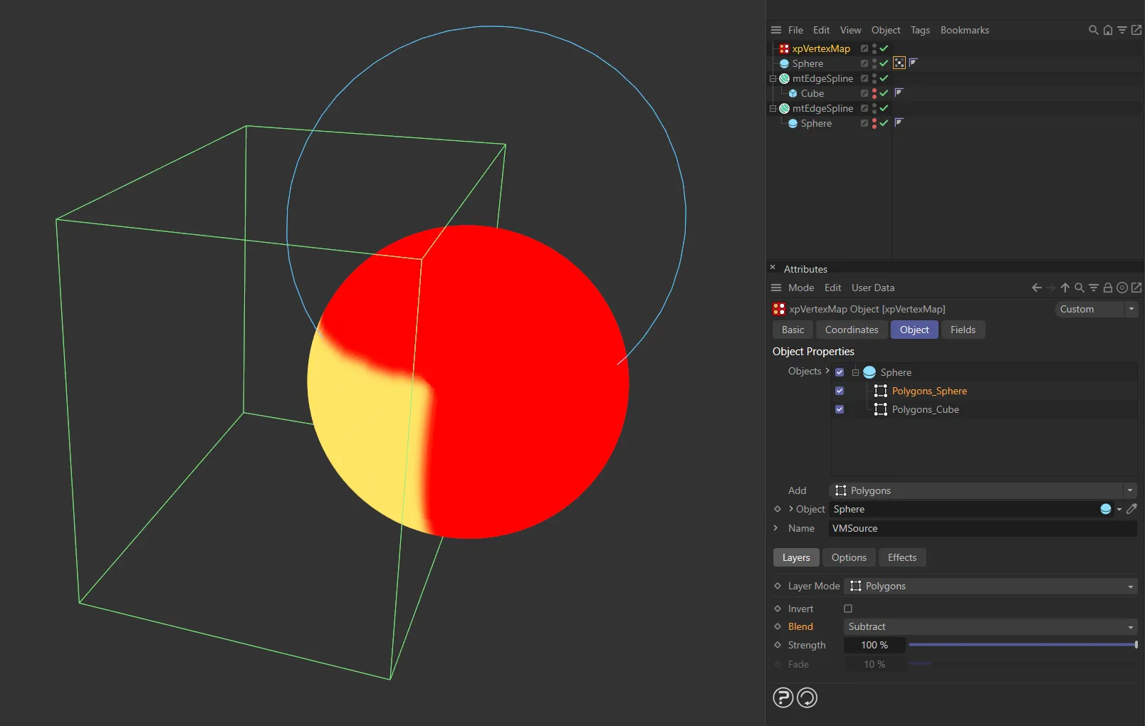
In this image, the Blend is set as Subtract.
Layers are evaluated from the bottom of the list upwards so, if you have three layers, layer 3 at the bottom is not blended with anything (as it has no layer below it); layer 2 is blended with layer 3 and finally layer 1 is blended with the result of blending layers 2 and 3.
When two layers are blended, they use the algorithm selected from this menu, which can be different for each layer, and the blend is weighted by the Strength setting in the upper layer of the two.
In order to better explain these Blend modes, the image below is used as a reference.
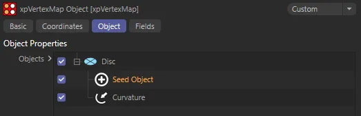
Disc object with two layers, Seed Object and Curvature.
Normal
Section titled “Normal”The values from the two layers are simply blended, using the strength setting in the Seed Object layer.
If the Strength is 100%, the Curvature layer values make no contribution to the overall result, which is entirely determined by the Seed Object values.
On the other hand, if the Strength is zero, the Seed Object values make no contribution to the overall result, which is entirely determined by the Curvature values.
The smaller of the two values from the Seed Object and Curvature layers is blended with the Curvature value.
Subtract
Section titled “Subtract”The Seed Object value is subtracted from the Curvature value and the result is blended with the Curvature value.
Multiply
Section titled “Multiply”The two values are multiplied together and the result is blended with the Curvature value.
The larger of the two values from the Seed Object and Curvature layers is blended with the Curvature value.
The two values are multiplied together and the result is blended with the Curvature value.
Screen
Section titled “Screen”This is the opposite of Multiply.
The two values are inverted, multiplied together and the result is inverted again then blended with the Curvature value.
Fade then Add
Section titled “Fade then Add”Adds vertex weights then fades them.
Strength
Section titled “Strength”This is the blend weight used to blend a layer with the layer(s) beneath it.
A value of 0 (zero) % will always result in the upper layer making no contribution to the final value, but a value of 100% does not mean that only the upper layer is used for the values, except when Blend is set to Normal.
Only available if Blend is set to Fade Then Add.
The higher the value, the faster the vertex weight will fade.
Options tab
Section titled “Options tab”Each layer type may have additional options that can be edited.
These are presented here for each layer type.
ExplosiaFX layer
Section titled “ExplosiaFX layer”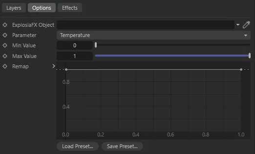
ExplosiaFX layer options.
With this option, the map is set from one of several parameters in an ExplosiaFX object.
The map is updated as the Explosia simulation plays, but resets to zero on rewinding the scene.
ExplosiaFX Object
Section titled “ExplosiaFX Object”The Explosia FX object to use.
The object to be weighted does not need to be an ExplosiaFX source object but it must be located within the solver bounds.
In this animation, the ExplosiaFX Object is driving the vertex map generation.
Parameter
Section titled “Parameter”Set as Temperature, by default.
The alternative parameters are: Smoke, Fire, Velocity (X), Velocity (Y), Velocity (Z), Color (R), Color (G) and Color (B).
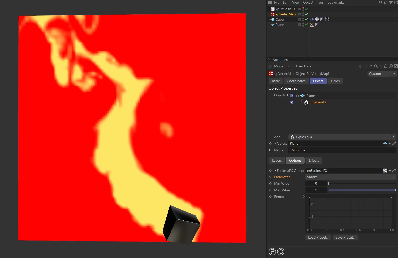
Parameter set as Smoke.
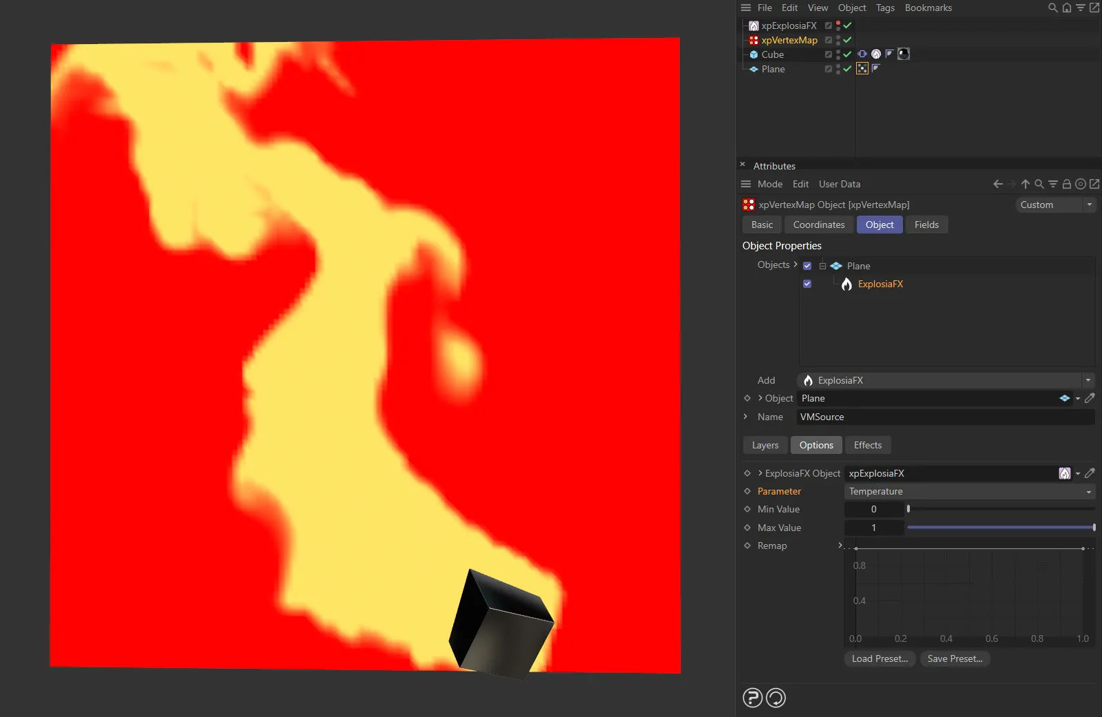
Here, the Parameter is Temperature.
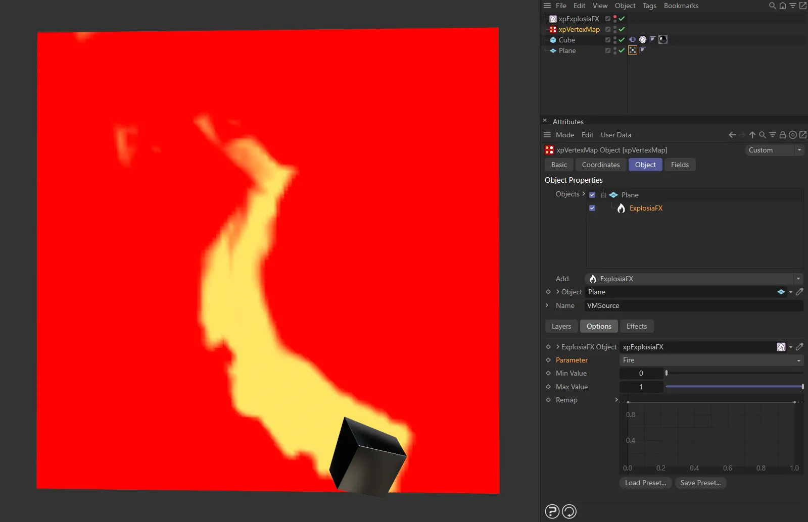
Parameter set as Fire.
Min Value, Max Value
Section titled “Min Value, Max Value”This is the range of weight values that can be set.
The defaults are 0 (zero) and 1 respectively, so the parameter from Explosia will be mapped to between those two values.
If you increase the minimum value to 0.25, for example, the minimum weight which will be set is 0.25.
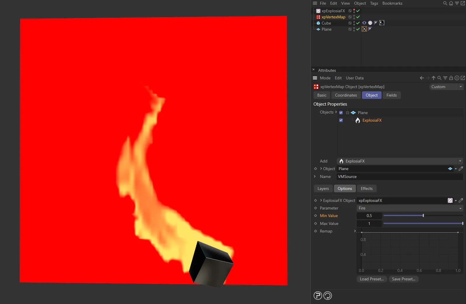
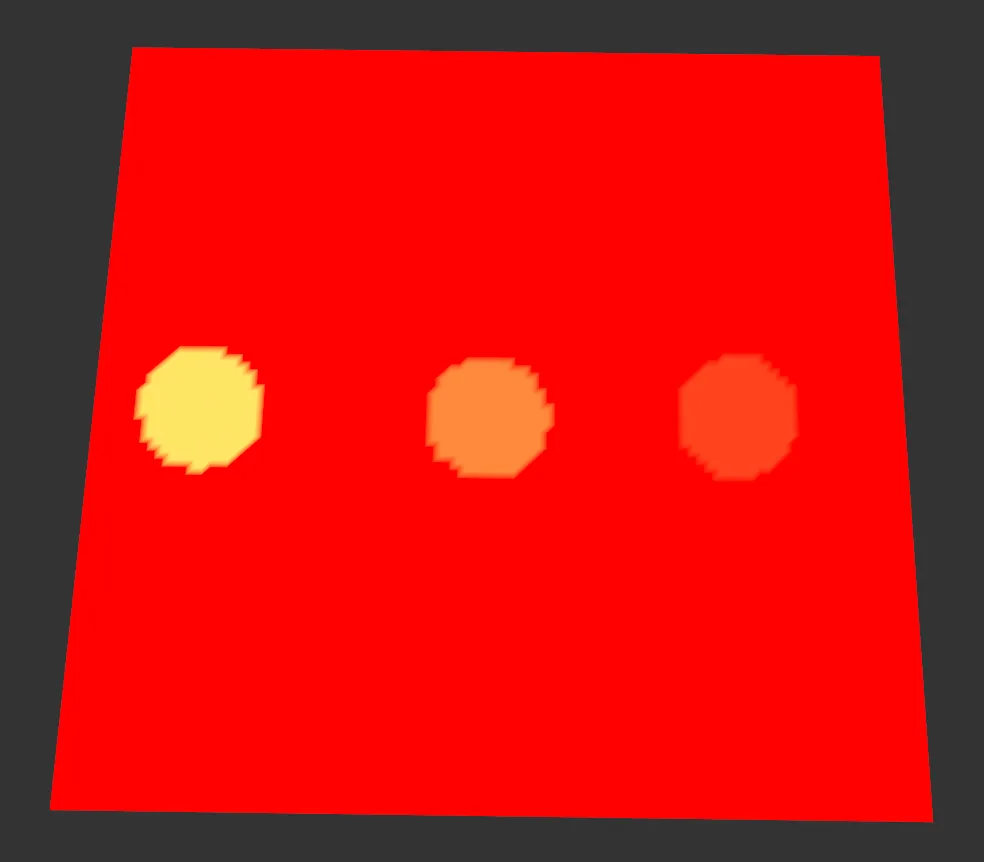
Min Value is set at 0.5 in this image.
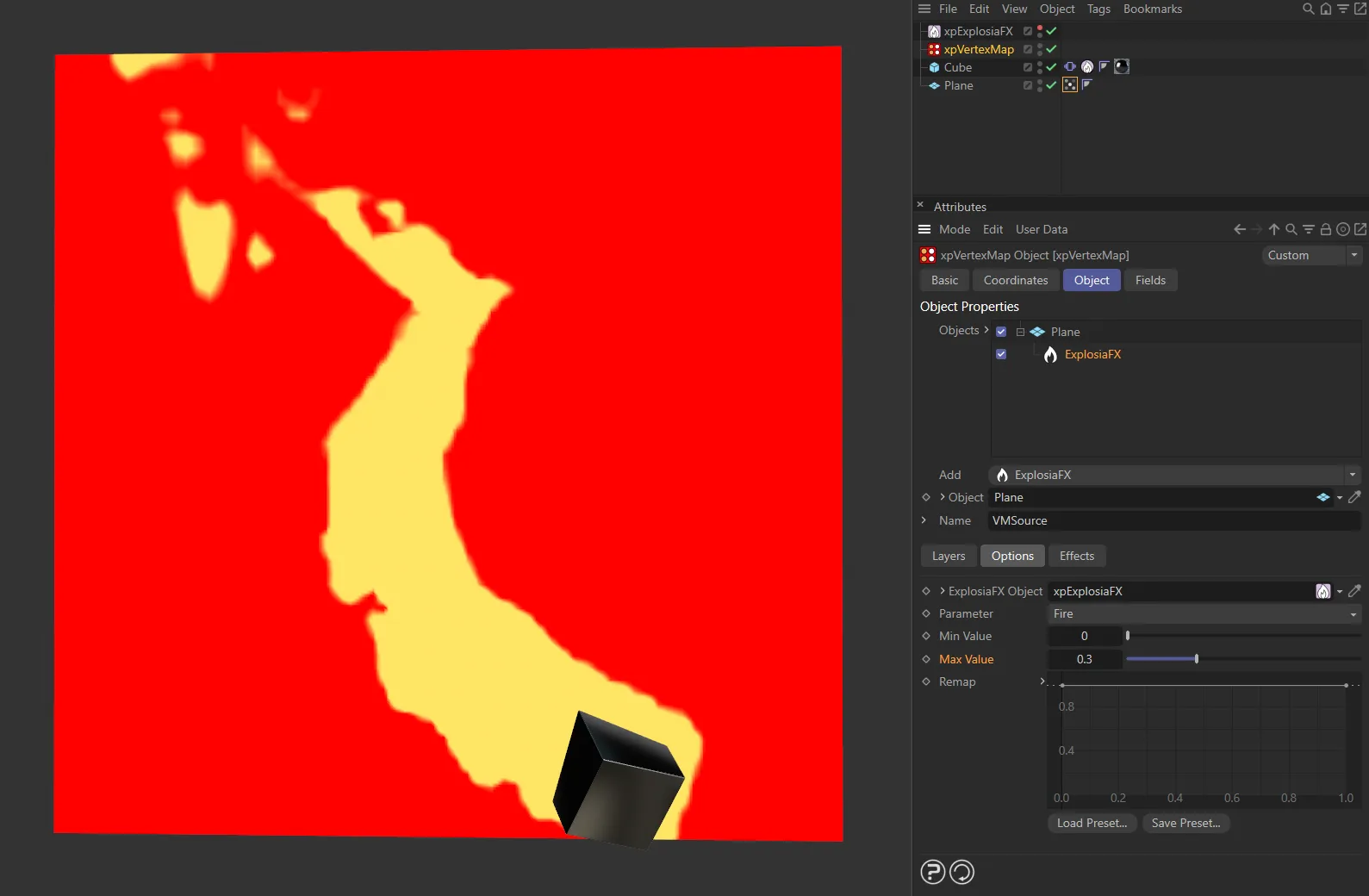
With Max Value set at 0.3 here, on the right.
This spline can be used to remap the calculated weight value.
In its default state it has no effect.
But if, for example, you lower the point at the right-hand end of the spline, so that it has a value of less than 1, this will be multiplied with the maximum calculated weight.
You can animate this spline to alter the map over time.
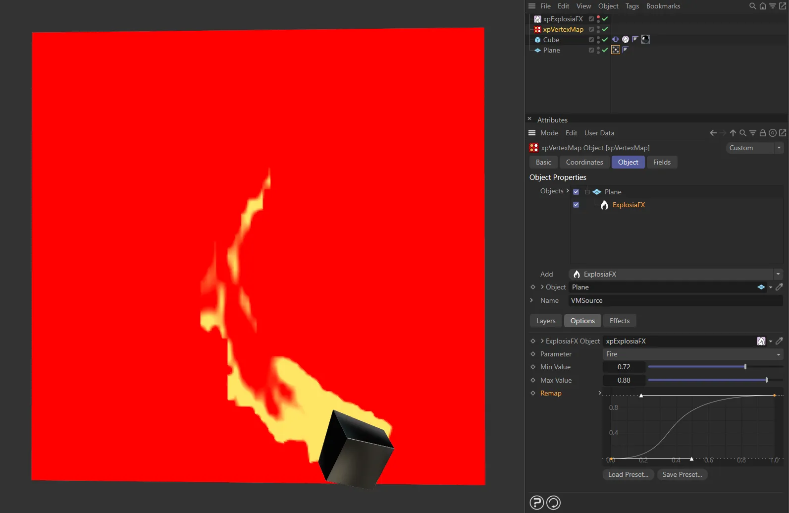
User driven remap curve, adding contrast to the vertex map.
Seed Object layer
Section titled “Seed Object layer”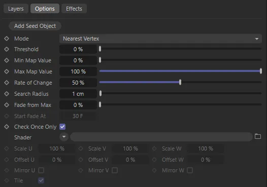
Seed Object layer options.
From a seed object in the middle of the mesh, the vertex map grows over the surface.
Add Seed Object
Section titled “Add Seed Object”Click this button to create a new seed object and add it to the scene as a child object of xpVertexMap.
Set as Nearest Vertex, by default.
The alternative settings are Reveal and Clone.
These settings are explained above.
Nearest Vertex
Section titled “Nearest Vertex”In this mode, the vertex map grows from one vertex to all those connected to it by an edge.
This produces a smooth growth but (if the object has many vertices) it is a slow growth.
Increasing the Search Radius parameter will cause the change in weight to occur over larger areas of the object.
If the Search Radius is too small, however, no growth may occur at all because the distance between vertices exceeds this value.
Animation to demonstrate the Mode setting of Nearest Vertex.
Reveal
Section titled “Reveal”Here, the vertex map is revealed as though a mask was being removed.
The mask is circular and spreads from the originating vertex with a speed set in the Search Radius parameter.
This animation shows the Mode setting of Reveal.
Threshold
Section titled “Threshold”Description coming soon.
Min Map Value, Max Map Value
Section titled “Min Map Value, Max Map Value”These are the minimum and maximum values the vertex weights can have.
Normally they are set to a minimum of zero and maximum of 100% but you can vary these, if required.
The assigned weights will not range outside these limits.
Rate of Change
Section titled “Rate of Change”This is the speed at which the weight changes from the initial value to its final value.
With the minimum and maximum map values at their defaults, and this value set to 50%, each vertex will take two frames to reach the final value.
Search Radius
Section titled “Search Radius”Only used if Mode is set to Reveal.
When a vertex weight reaches its maximum value, it will then search for neighbouring vertices.
If any of them have not started to change weight, and are within this distance of the initial vertex, they will start to change.
If this value is too low, there may be no vertices within that range and no change in the vertex map will occur.
If it is too high, the map may change more quickly than desired since a larger number of vertices start to change.
Fade from Max
Section titled “Fade from Max”This function will only work if Mode is set to Nearest Vertex.
If this value is anything other than 0 (zero), the vertex weight will start to fade once the time in Start Fade At has elapsed.
This will cause the weight to decrease to zero (or increase to maximum if the Invert setting is enabled).
The higher the value in this setting, the faster the weight will fade.
In this animation, Fade from Max is set at 1%.
Fade from Max raised to 15%.
Finally, Fade from Max set to 100%.
Start Fade At
Section titled “Start Fade At”This function will only work if Mode is set to Nearest Vertex.
This is the time after which a vertex weight will start to fade.
The countdown does not begin until a vertex weight starts to grow.
This setting is not available if the Fade From Max value is at 0 (zero) %.
Animation with Start Fade At set at 5 frames in.
Here the Start Fade At is set at the 45th frame.
Check Once Only
Section titled “Check Once Only”By default, this option is enabled.
It ensures that, once a vertex has checked for any neighboring vertices in order to start growing the vertex weight, that vertex will not search again.
This speeds up the process considerably.
If it is unchecked, each vertex is checked each frame, which is time-consuming.
The only reason for unchecking this option is when a mesh is animated so that vertices may become closer to one another over time and may come within the Search Radius distance, or when using an animated shader.
Shader
Section titled “Shader”A link field for a channel shader.
This shader will control the rate at which a vertex weight increases and the maximum value the weight can reach.
In this animation, there is a Noise shader, with an animation speed of 1. The Seed Map layer object is set to the Add blending mode so that the visual effect continues to add on top of itself.
Using a noise shader, for example, the vertex weights will grow faster in areas which are brighter and the maximum weight will also be higher in those areas.
Using a shader is not essential.
If you don’t use one, the values in Min Map Value and Max Map Value determine the limits on the vertex weight.
It also means that each vertex weight will grow at the same rate.
Scale U, Scale V, Scale W
Section titled “Scale U, Scale V, Scale W”These three parameters control the size of the shader across the sample space.
If the Tile parameter is enabled, a bitmap will be tiled across the sample space and the number of tiles is controlled by these parameters.
If Tile is unchecked, or for procedural shaders, the shader is simply scaled.
Offset U, Offset V, Offset W
Section titled “Offset U, Offset V, Offset W”The shader will be offset by these amounts in the respective direction.
Mirror U, Mirror V, Mirror W
Section titled “Mirror U, Mirror V, Mirror W”Enabling these settings will mirror the shader across the respective axis.
If a bitmap is used, enabling this will cause it to be tiled across the sample space.
The number of tiles is controlled by the Scale U and Scale V settings.
The setting has no effect on procedural shaders.
Seed Map layer
Section titled “Seed Map layer”The Seed Map layer gives the user control over the growth speed of vertex map weighting.
This layer type has the same options as Seed Object plus others, to allow you to select a vertex map to use as the seed.
In the first video, the Vertex Map is generated directly from another xpVertexMap object, generating the vertex map through the Surface mode of a Polygons layer.
In this second animation, there is an existing, user-generated Vertex Map. This is then linked to the xpVertexMap’s Seed Map layer and, as the scene plays through, the vertex weight grows.
Vertex Map to Use
Section titled “Vertex Map to Use”Set as First, by default, this menu allows you to select the vertex map to use as a seed.
The other options are: Linked and Named.
The first vertex map on the object will be used as the seed.
Linked
Section titled “Linked”A vertex map from the object can be dragged into the upper Vertex Map field and that will be used as the seed.
Alternatively, type the name of the map to use into the lower Vertex Map field.
Vertex Map
Section titled “Vertex Map”These two fields have the same name.
The first is enabled when Vertex Map to Use is set to Linked; it is a link field which accepts a vertex map tag.
The second is enabled when Vertex Map to Use is set to Named; it is a text field into which you enter the name of the tag to use.
Set as Nearest Vertex, by default.
The other settings are Reveal or Clone.
These settings are explained above, with the exception of Clone.
If you have added another map by setting Vertex Map to Use to Linked or Named, then this option simply clones the map and will not use it as a seed - the map is simply used as it is.
This enables you to add maps which have been output from other objects and perhaps combine them with additional maps generated by the xpVertexMap object.
Threshold
Section titled “Threshold”The Threshold parameter dictates which vertex weighting is passed over to the xpVertexMap Seed Map layer.
This image is the base seed map being used to drive the xpVertexMap Seed Map layer. The seed map has three user-set areas with different weights of 100%, 60% and 30%.
In this animation, at a Threshold value of 100%, only the first seed area is able to be generated. As the Threshold value decreases, the xpVertexMap Seed Map layer includes the seeds with lower weights.
Min Map Value, Max Map Value
Section titled “Min Map Value, Max Map Value”These are the minimum and maximum values the vertex weights can have.
Normally they are set to a minimum of zero and maximum of 100% but you can vary these if required.
The assigned weights will not range outside these limits.
Rate of Change
Section titled “Rate of Change”This animation demonstrates the effect of the Rate of Change parameter, set at a value of 90%.
Here, Rate of Change is lowered to 10%
Search Radius
Section titled “Search Radius”This animation shows the Search Radius of 25cm driving the change of vertices within that distance.
In this animation, the Search Radius has been lowered to 5cm.
Fade from Max, Start Fade At, and remaining parameters…
Section titled “Fade from Max, Start Fade At, and remaining parameters…”These parameters are identical to the section above for the Seed Object layer.
Polygons layer
Section titled “Polygons layer”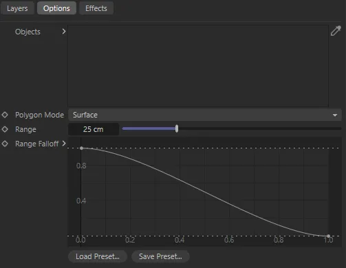
Polygons layer options.
In this mode, the polygon face or the volume of an object is used to generate the map.
Objects
Section titled “Objects”Drag the polygon objects to use into this list.
Polygon Mode
Section titled “Polygon Mode”Set as Surface, by default.
The alternative setting is Volume; both are described above.
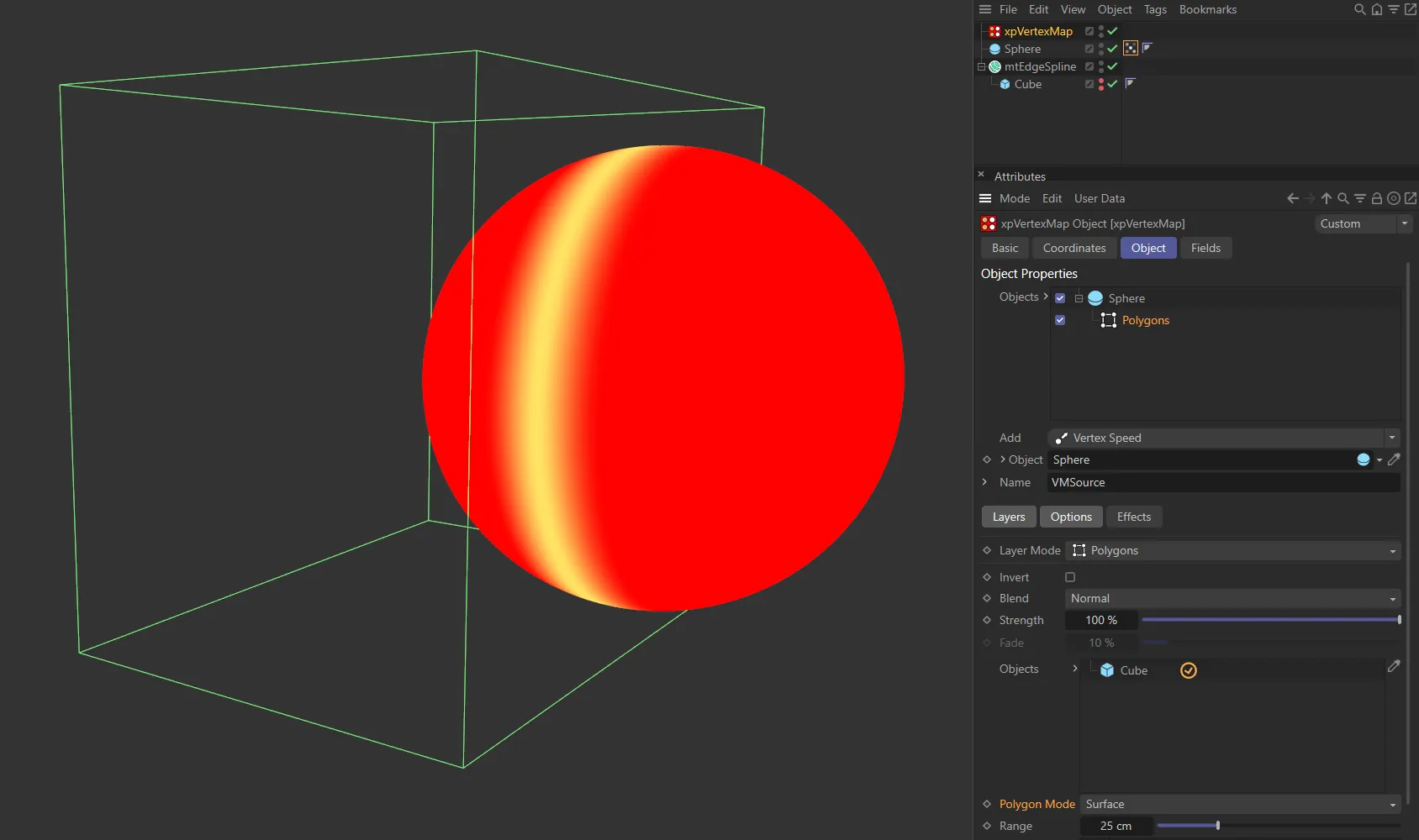
Here the Polygon Mode is set as Surface.
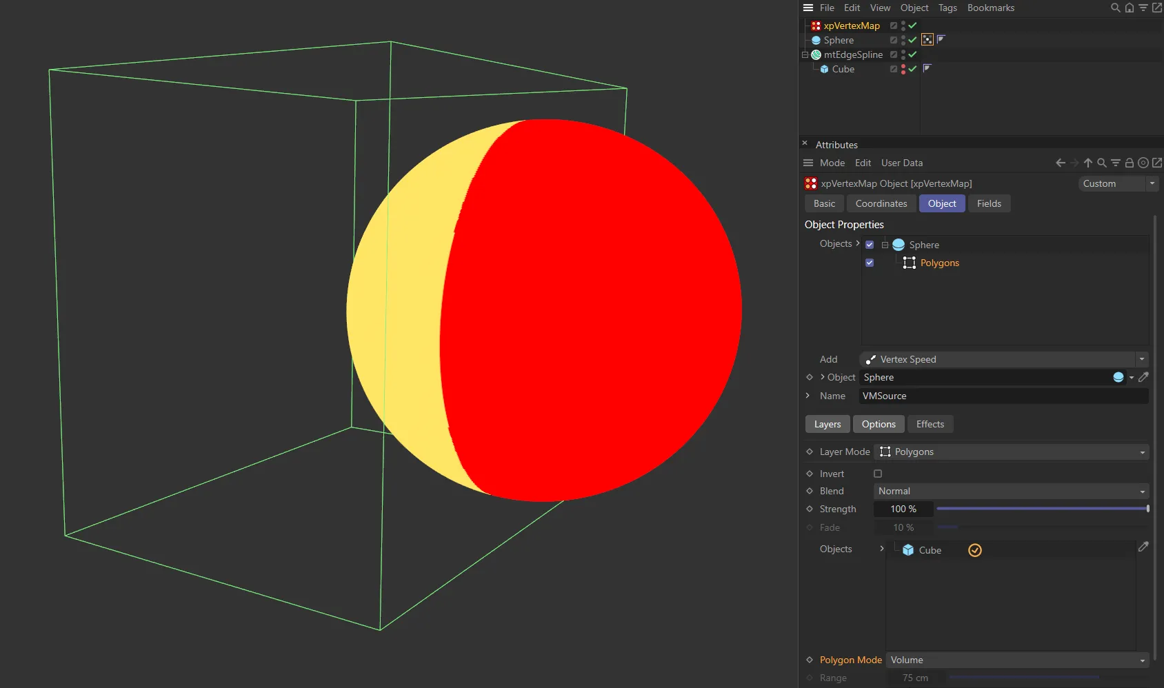
The Polygon Mode is in the other setting of Volume in this image.
Only available if Polygon Mode is set to Surface.
A vertex must be no more than this distance away from a polygon surface for the vertex to be weighted.
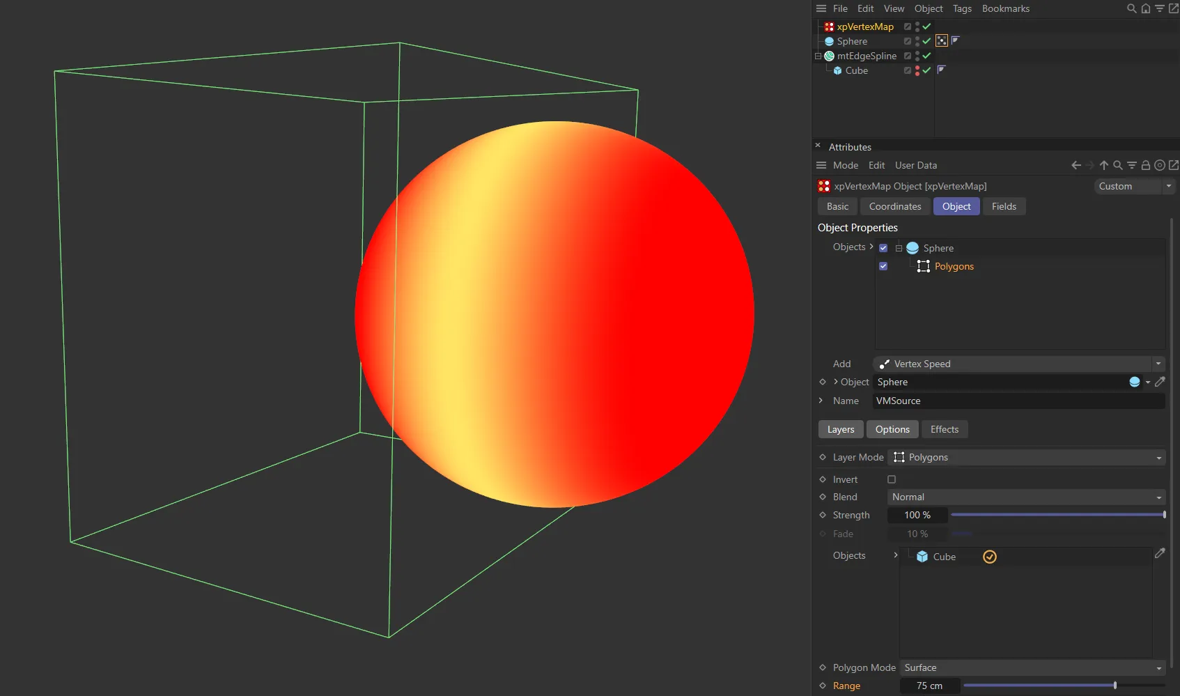
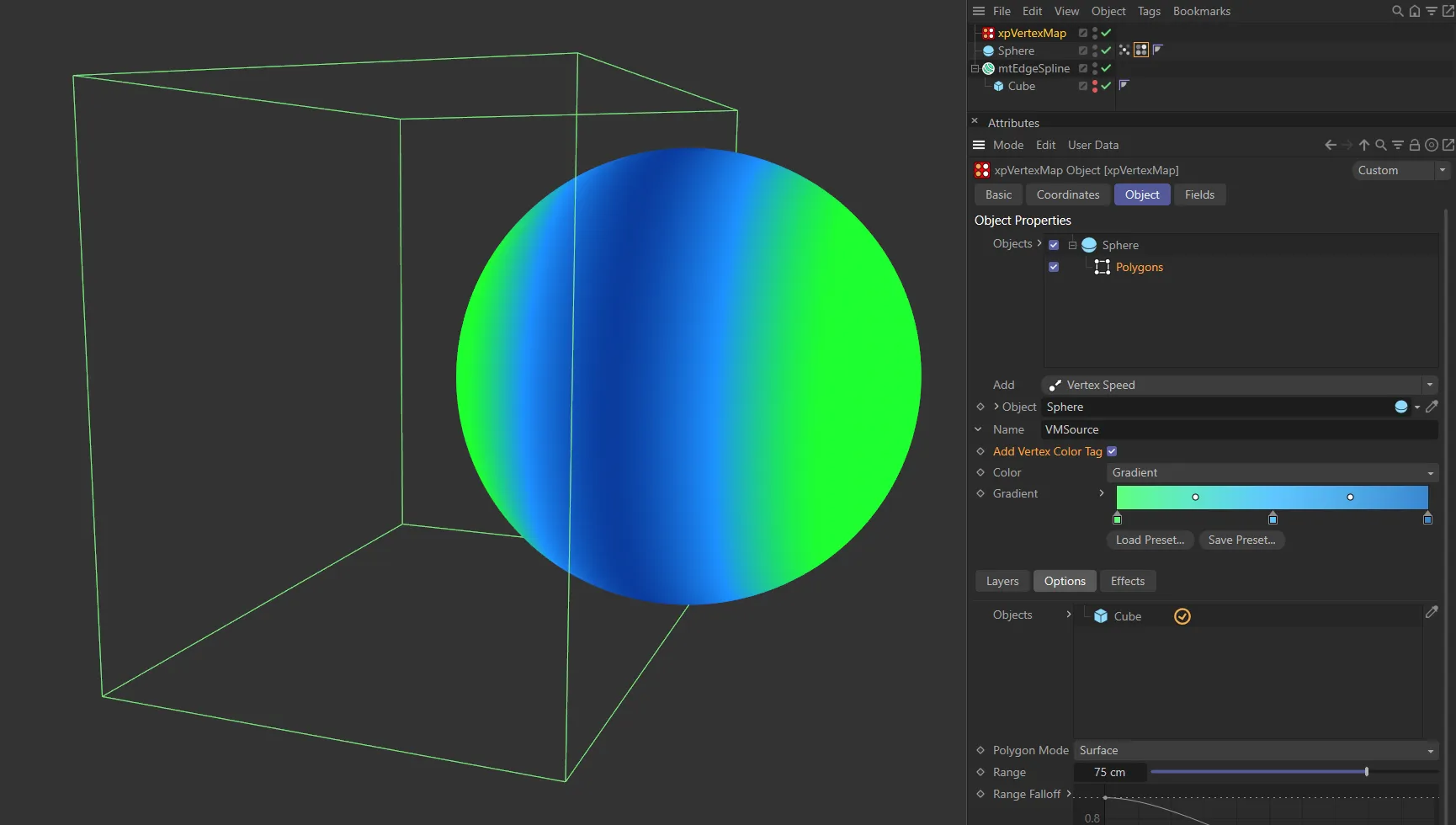
With the Polygon Mode set at Surface and the Range value at 75cm, using the intersecting edge of the Cube (in the Objects list) for vertex map generation.
Range Falloff
Section titled “Range Falloff”If Polygon Mode is set to Surface, this spline can be used to alter the weight value from the surface intersection.
A value between 0 (zero) and 1 is obtained from the spline, depending on the distance between the weighted vertex and the surface or volume.
This value is then multiplied with the weight to give the final result.
With the default spline shown above, if the distance is zero (left-hand end of the spline) the full weight is used.
If the distance is equal to or greater than the value in Range (right-hand end of the spline), the weight or rate of change will be zero.
If Polygon Mode is set to Volume, the Range setting does not apply so only the left-hand point of the spline is used.
The spline causes a uniform change in weight across all weighted vertices.
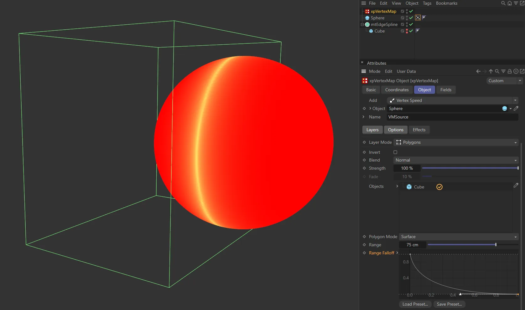
Vertex map generated by the Range Falloff spline setting, using the same intersecting edge of the Cube for generation.
Splines layer
Section titled “Splines layer”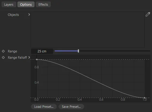
Splines layer options.
The Splines layer is almost identical to the Polygons layer, except that there is no Polygon Mode setting and vertices are weighted when they are close to the the spline itself (not just its vertices).
The Range Falloff spline can then be used to adjust the overall weight as in the Polygons layer.
Texture layer
Section titled “Texture layer”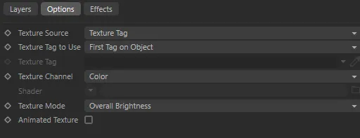
Texture layer options.
This layer will generate a vertex map using a texture.
Texture Source
Section titled “Texture Source”Set as Texture Tag, by default.
The alternative is Shader.
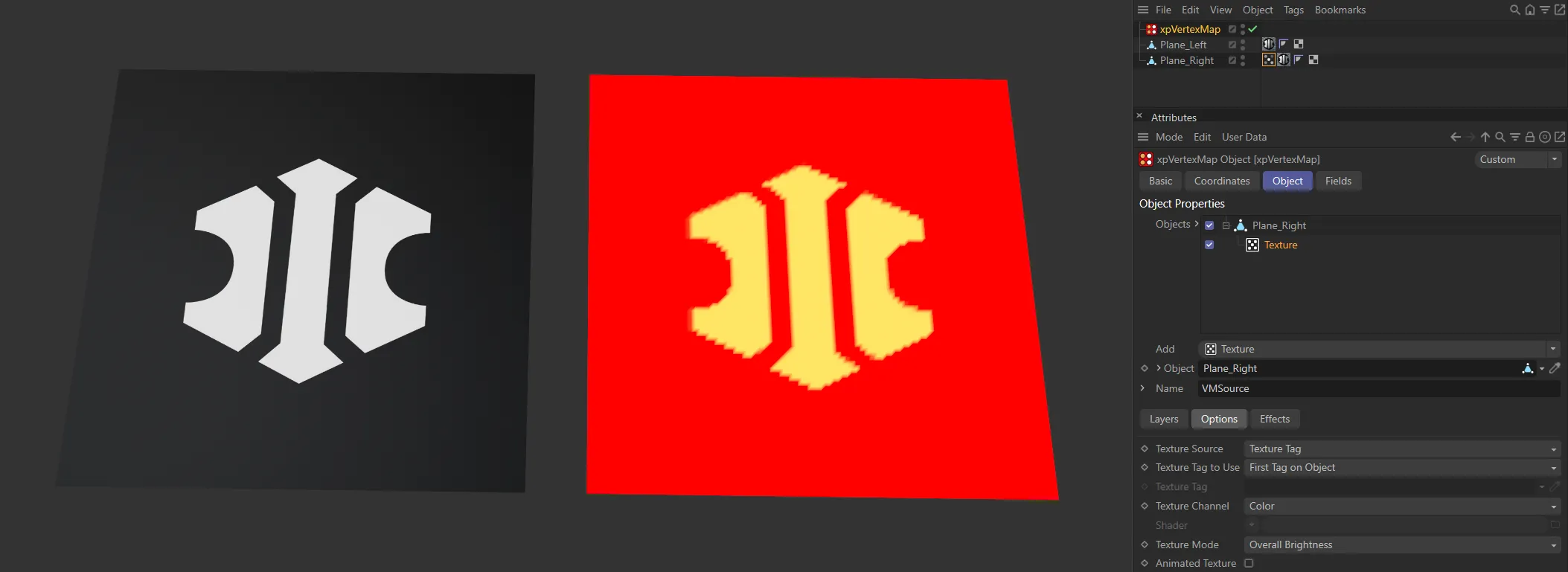
This vertex map is generated by the bitmap image in the Texture Source setting of Texture Tag.
Texture Tag to Use
Section titled “Texture Tag to Use”Set as First Tag on Object, by default.
The alternative is Selected Tag.
First Tag on Object
Section titled “First Tag on Object”The first texture tag on the object will be used.
Selected Tag
Section titled “Selected Tag”You can select the desired tag by dragging it into the Texture Tag field.
Texture Tag
Section titled “Texture Tag”Drag the texture tag you want to use from the parent object into this field.
Only available when Texture Tag to Use is set to Selected Tag.
Texture Channel
Section titled “Texture Channel”This drop-down is a list of possible texture channels to sample.
You can use any of these channels, so you can use a channel which is not being used to render the material, if you like.
Shader
Section titled “Shader”Use the drop-down menu to select the Shader object you wish to use.
Only available when Texture Source is set to Shader.
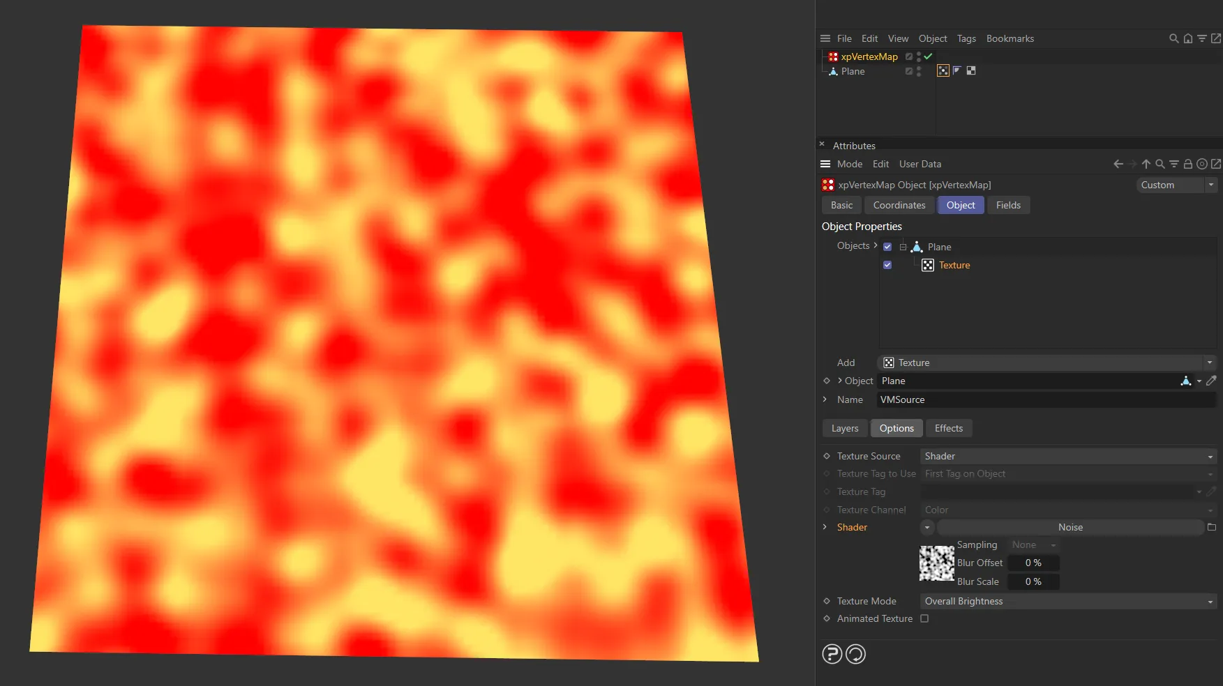
With Texture Source set to Shader, this vertex map is being driven by the Noise shader.
Texture Mode
Section titled “Texture Mode”This drop-down controls how the texture color will be used to generated the vertex map.
The default is Overall Brightness, which uses the color brightness to generate the map.
This means that a color of pure red will generate the same vertex map as a pure blue color, since they have the same brightness but a different hue.
To use different colors you can select the Red Only, Green Only or Blue Only options.
With these, the brightness of each color in the sampled texture will control the vertex map weights.
Animated Texture
Section titled “Animated Texture”Check this box to update the vertex map each frame, if an animated texture is used.
Animation to show the vertex map (on the right) being updated each frame, with Animated Texture enabled and the vertex map being generated by the file on the left.
Vertex Speed layer
Section titled “Vertex Speed layer”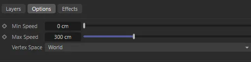
Vertex Speed layer options.
This layer uses the speed in the 3D world of the vertices of the object which holds the vertex map.
It therefore requires a moving object or nothing is generated.
The vertex map weights will be generated by the speed of each vertex as it moves, when the animation is played.
The vertex speed is assigned a weight from 0 (zero) to 1, using a range set with the Min Speed and Max Speed parameters.
If the speed is lower than the minimum, the vertex weight is zero; if it is greater than the maximum, the vertex weight is 1.0.
Choose the speed range carefully in order to see the maximum change in weight.
In this animation, with the Layer Mode set as Vertex Speed, the vertex map is being generated by the speed at which the vertices of the Cube are moving. Note: The Vertex Space parameter (in the Vertex Speed layer) is set to World, so the vertex speed is measured by comparing differences in vertex positions against the world space over time.
Min Speed, Max Speed
Section titled “Min Speed, Max Speed”The minimum and maximum speed settings for the speed range.
The Min Speed is 150cm here.
Animation showing a Max Speed value of 200cm
Vertex speeds within this range will have a weight value from 0 (zero) to 1.
Vertex Space
Section titled “Vertex Space”Set to World, by default, this parameter lets you choose between two spaces for calculating the vertex speed.
If you are moving some vertices in a mesh relative to other vertices you might want to use Local and then moving the object as a whole won’t affect the weight.
However, if you move the entire object, you need to use World space, to see any change in the weights.
The vertex speed is relative to the other vertices in the object.
With this setting, if you only animate the movement of the object, rather than the individual vertices, the vertex weight will always be zero, since the vertices are not moving, relative to other vertices.
If you animate some or all of the individual vertices, their speed is calculated each frame and the vertex weight generated from that speed.
The Vertex Space in this animation is set to Local, with xpVertexMap assessing the changes in vertex location relative to the object’s position. Therefore we see changes in vertex weight when we have quick moving animated vertices.
The vertex speed is relative to the object’s position.
This is the option to choose if you are animating an entire object (even if some vertices also move independently of the object’s position and others do not).
X-Particles/Vertices layer
Section titled “X-Particles/Vertices layer”This animation demonstrates the effect of the Layer Mode of X-Particles/Vertices.
In this layer, you can use an X-Particles emitter or any object with vertices.
The map will be weighted when the particle or vertex comes closer then the Range value.
The vertex map is being driven by the Range value of 60cm, together with the Range Falloff, in this animation.
A different Range Falloff curve and a Range value of 25cm drives this vertex map generation.
The parameters are the same as the Polygons layer.
In this case, an X-Particles emitter or any object with vertices can be dragged into the Objects list.
There is also one additional setting.
Groups
Section titled “Groups”If you drag particle groups into this list, only particles in those groups are used to generate the map.
If the list is empty, all particles are used.
In this animation, only particles in Particle Group 2 are driving the vertex map generation.
Curvature layer
Section titled “Curvature layer”The vertex map is weighted using the curvature of the object at each vertex.
There are no additional options.
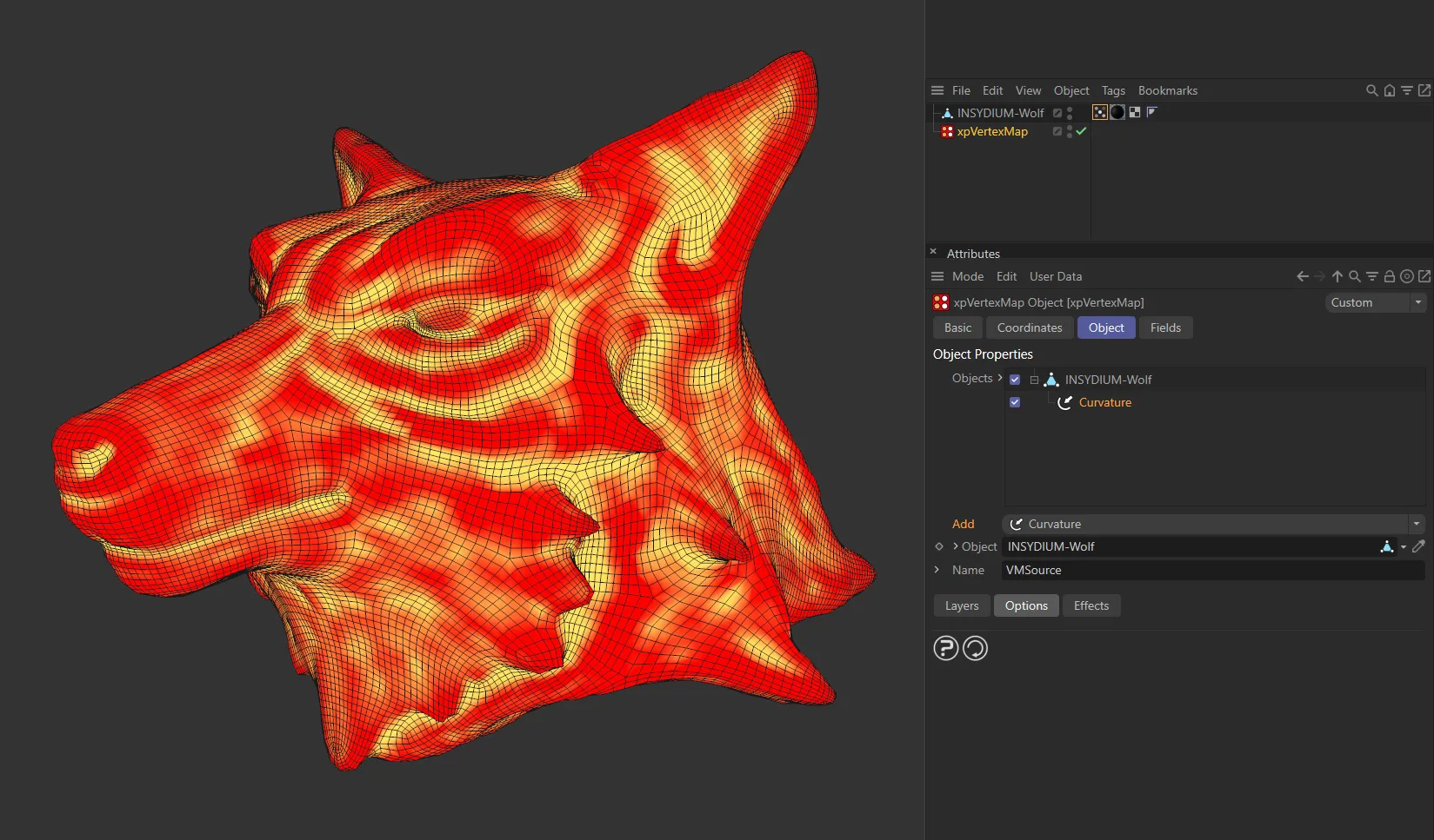
This image demonstrates the Curvature layer driving the vertex map on the INSYDIUM-Wolf.
Ambient Occlusion layer
Section titled “Ambient Occlusion layer”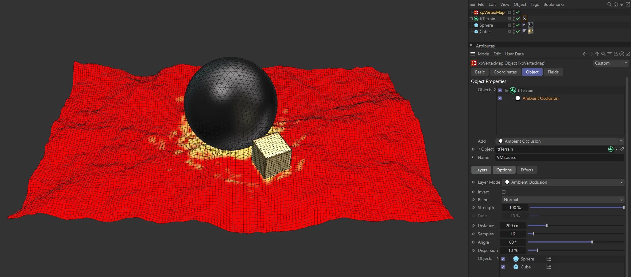
Layer Mode set as Ambient Occlusion.
This layer weights the vertex map depending on ambient occlusion from another object.
Distance
Section titled “Distance”The object causing ambient occlusion must be within this distance from the point being sampled.
The map will become brighter the closer the occluding surface is.
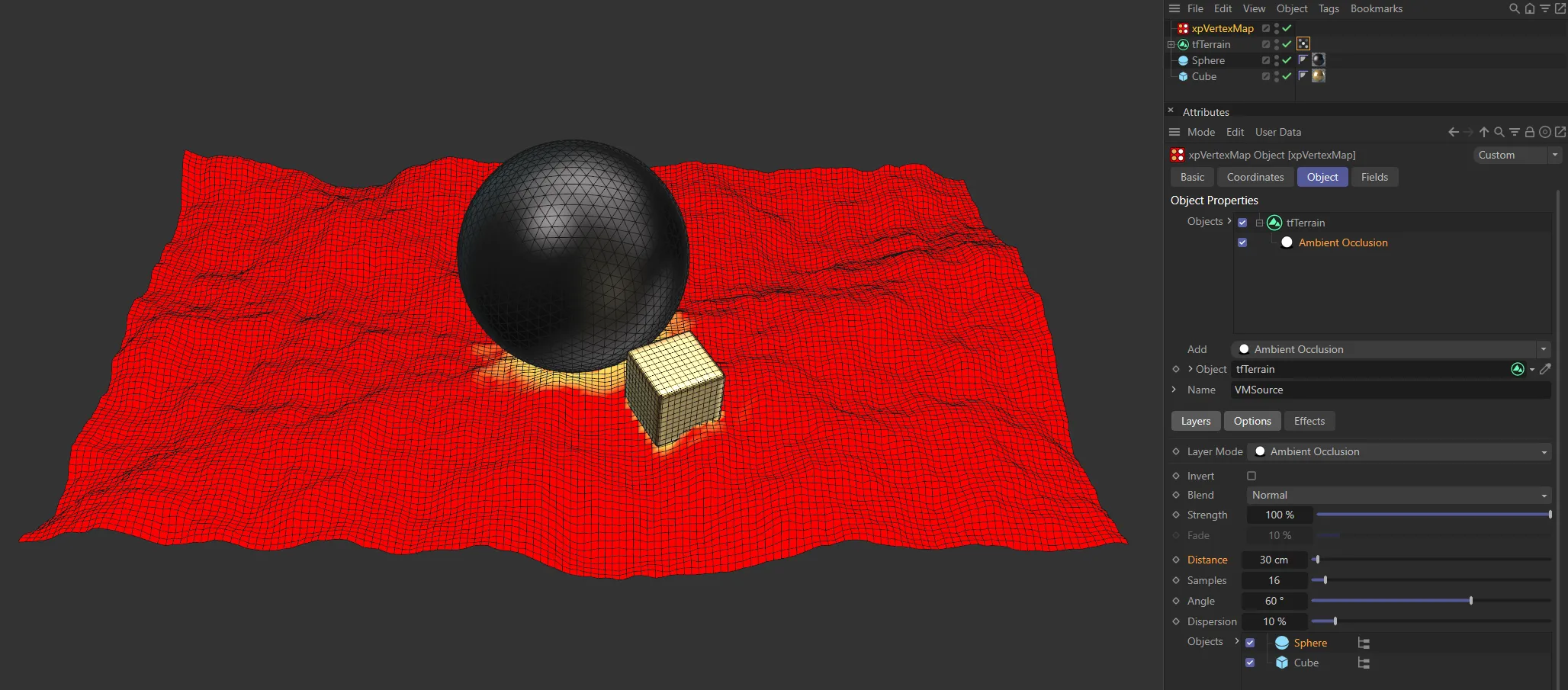
Here, the settings are identical to the image above, except the Distance value has been reduced to 30cm.
Samples
Section titled “Samples”The number of samples taken.
More samples produce a more accurate result; this is handy when using a high-poly mesh, but will be slower to calculate.
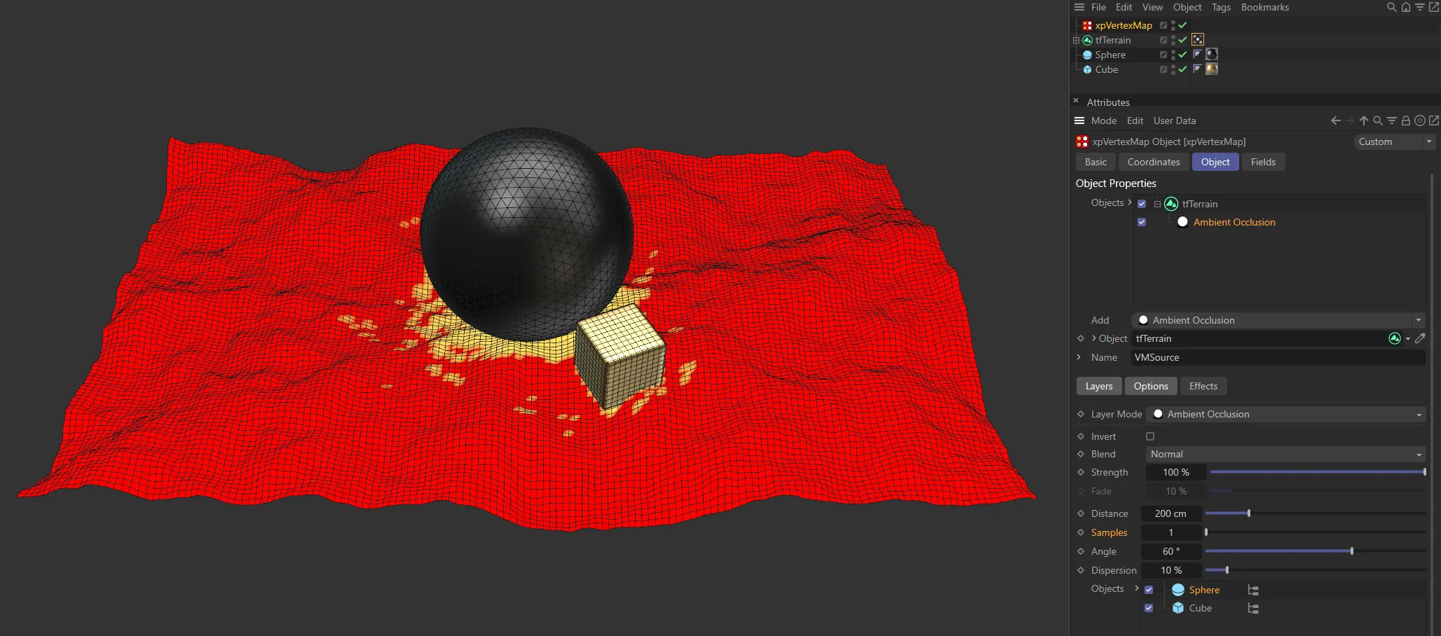
Again, the settings are the same (with the original Distance of 200cm), but the Samples value has been reduced to 1, lowering the accuracy.
This is the cone around the surface normal when calculating ambient occlusion.
Reducing this value will reduce the dispersion of the ambient occlusion but may require the Samples value to be increased.
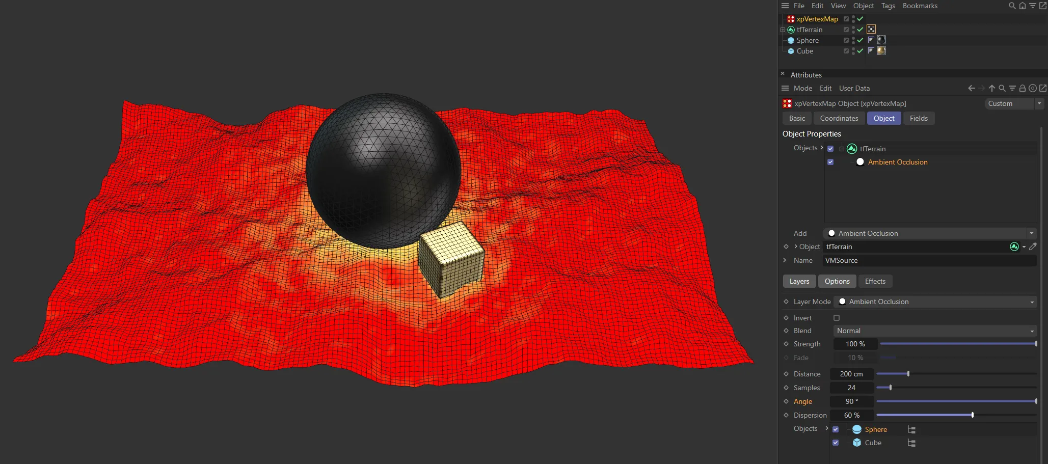
This first image has a higher Angle setting of 90 degrees.

The Angle value is reduced to 18 degrees in this second image.
Dispersion
Section titled “Dispersion”The amount of dispersion of the vertex weights.
The higher this value, the greater the spread of the vertex weights over the surface.
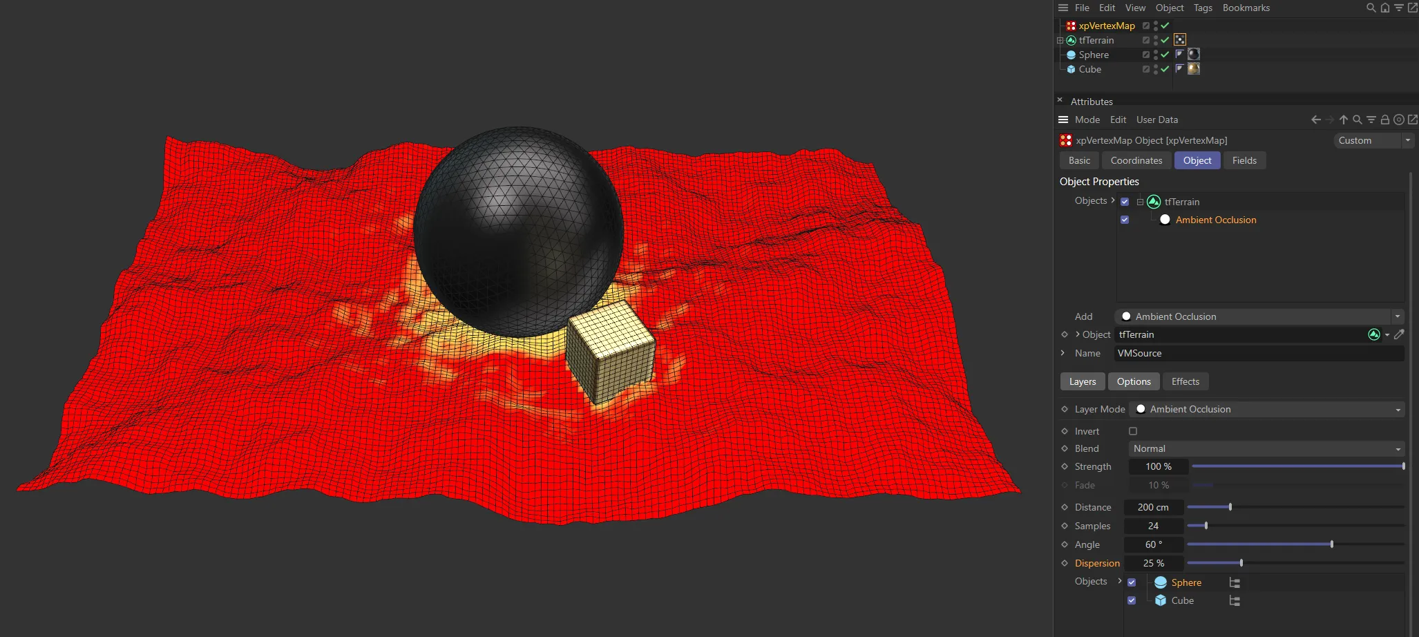
The Dispersion is set at 25% in this first image.
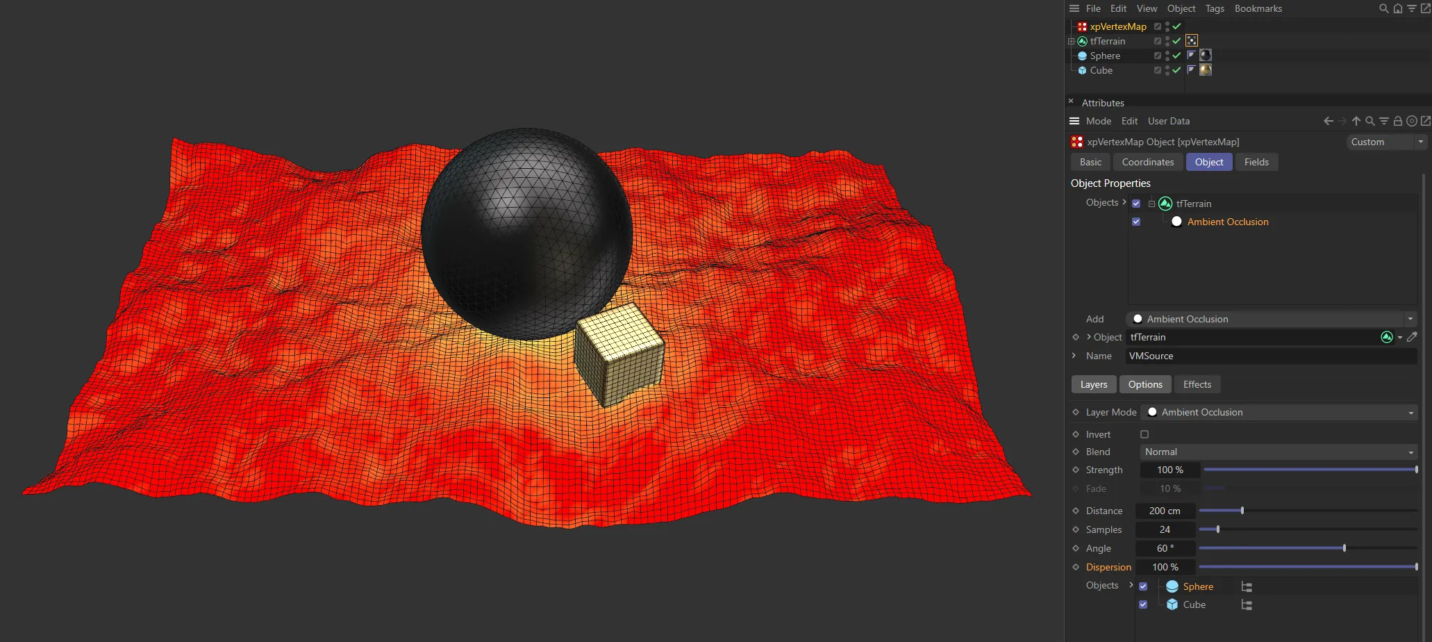
Compare the first image with these results when the Dispersion is raised to 100%.
Objects
Section titled “Objects”Drag any occluding objects into this list.
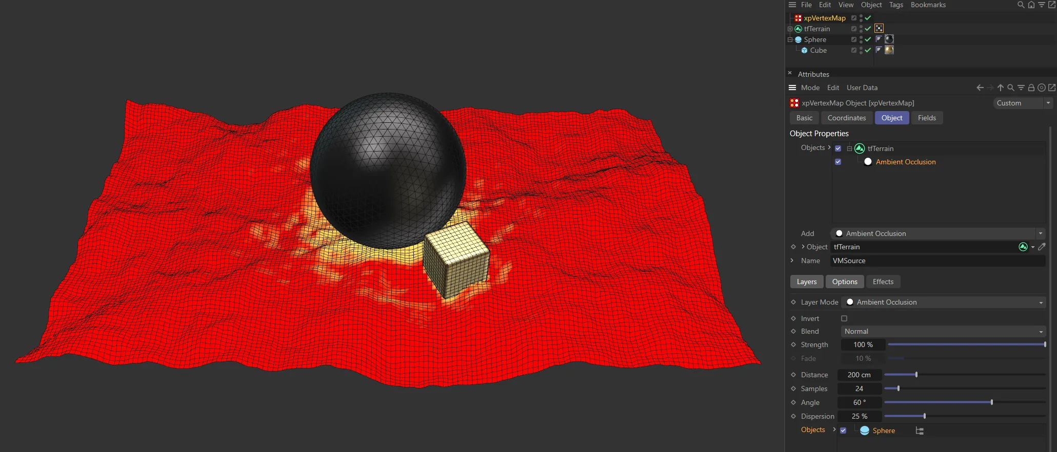
The hierarchy is enabled here, so both the Cube and Sphere (in the Objects list) are generating the vertex map.

In this second image, the hierarchy is disabled, removing the Cube (as a child object of the Sphere) from the vertex map generation.
Effects tab
Section titled “Effects tab”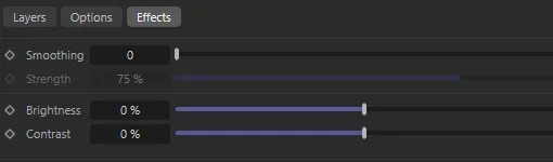
Effects tab settings.
These settings are common to all layer types.
Smoothing
Section titled “Smoothing”The number of smoothing iterations.
The higher the number, the more accurate smoothing will be, but it will take longer.
If set to 0 (zero), there is no smoothing.
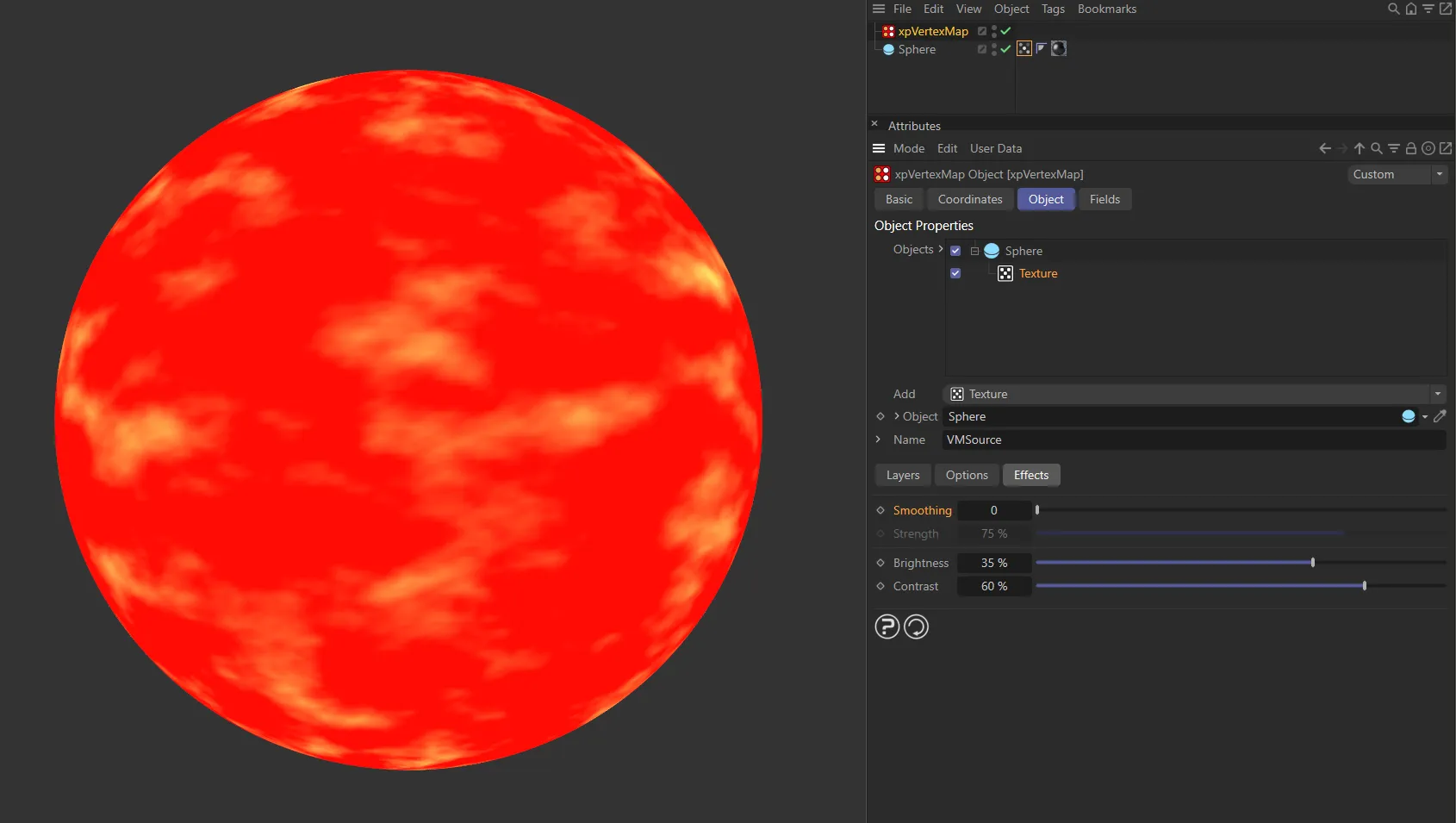
This first image has Smoothing set on 0 (zero), with no smoothing present.
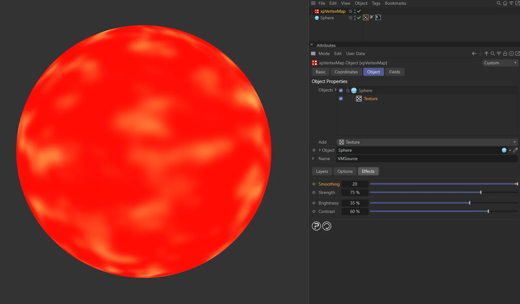
In this second image, with Smoothing set at 20, the smoothing between colors is very accurate.
Strength
Section titled “Strength”The amount of smoothing.
Brightness
Section titled “Brightness”Increase or decrease this value to increase or decrease the overall brightness of the vertex map.
Contrast
Section titled “Contrast”You can alter the contrast between different weights in the map with this setting.
Copyright © 2026 INSYDIUM LTD. All rights reserved.