xpTrailDeformer
The xpTrailDeformer is used in the same way as any other deformer in Cinema 4D, but acts only on spline objects.
You can use it on any spline, but it is specifically intended for use with the xpTrail object.
Formula Displacement is the core of the deformer.
It functions in a similar way to the Formula Deformer that comes with Cinema, but with some differences.
The way the deformer works is that, for each point in the spline, a displacement along one or more of the axes is calculated and added to the current spline point coordinate.
An example would be the simplest possible formula, consisting of a single number - ‘2’ - so you would type ‘2’ into the formula fields.
The deformer takes that value and multiplies it by the value in the Amplitude parameter.
If that is the default of 20 units, the result is 2 x 20 = 40.
The value ‘40’ is then added to the point’s coordinate value.
If this was added to the Y coordinate, the effect would be to move all the points in the spline along the positive Y axis by 40 units.
With more complex formulas you can do a lot more than that.
The default formula in the deformer is along the Y axis of the point and reads:
Sin((u + t) * 360)
Section titled “Sin((u + t) * 360)”A very simple formula, but the effect is to displace the spline along to Y to produce a sine wave.
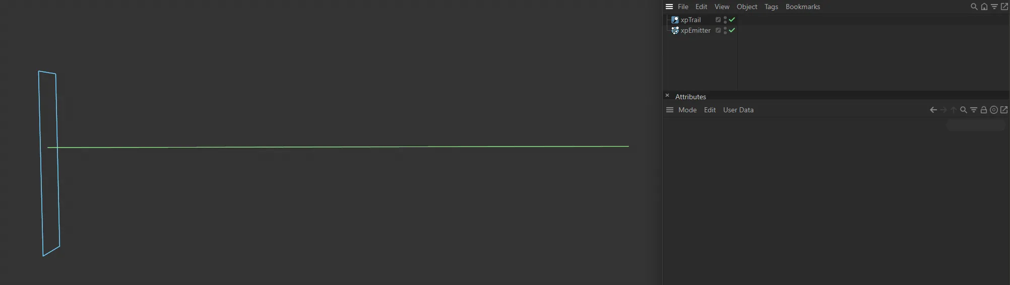
This image demonstrates the xpTrail generated base spline.
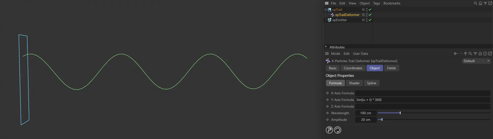
Sine wave created from the default formula of Sin((u+t)*360).
You can use all the mathematical functions supported by Cinema 4D (see the Appendix in Cinema’s online help for details) and can also use a few special symbols added by this deformer.
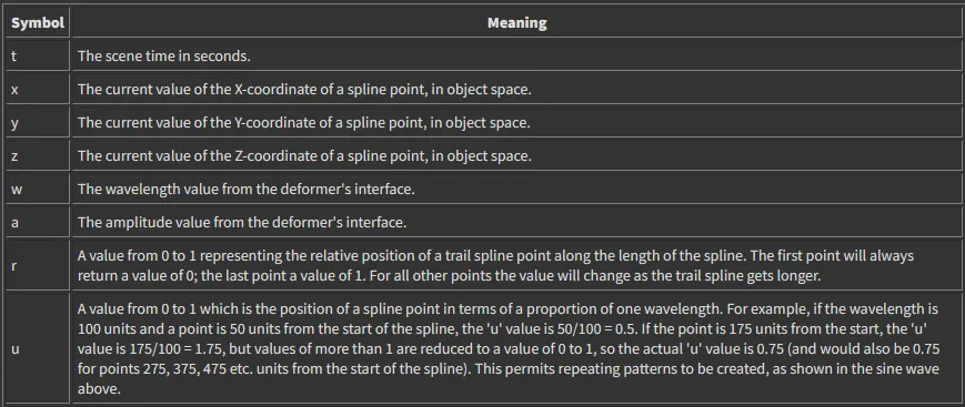
The additional special symbols added by this deformer.
You can use different formulas for the formula fields or use the same formula in both (which is often not very useful) or only use a formula for one axis.
An empty formula field has no effect on the spline point.
Since this is then multiplied by the amplitude, this gives a displacement of zero along that axis (i.e. no effect).
The same result would be achieved by entering the value ‘0’ in the formula field.
Errors in the formula also return zero.
If your formula appears to have no effect, it may have an error such as a symbol that isn’t recognised or an imbalance in the number of parentheses used in the formula.
If you need to include angles in the formula, these are always in degrees (e.g. enter ‘360’ not ‘pi * 2’ if you want an angle of 360 degrees).
You can displace the trail spline points using a shader as well as, or instead of, a formula.
The amount of displacement is given independently in the Displacement parameter.
Any shader can be used, including animated ones.
Some, of course, will be much more useful than others; the one which you will probably use most is Noise.
The blend between formula and shader displacement is controlled by the Mix parameter.
By default this is set to 0 (zero) %, which means no contribution from the shader (if any) and the displacement is entirely due to the formula (if there is one).
A value of 100% means that the shader controls the displacement completely, with no effect from the formula.
Formula tab
Section titled “Formula tab”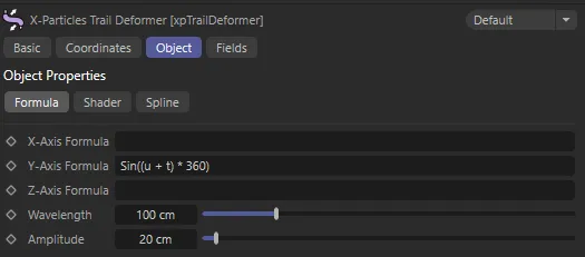
xpTrailDeformer Formula tab menu settings.
X-Axis Formula, Y-Axis Formula, Z-Axis Formula
Section titled “X-Axis Formula, Y-Axis Formula, Z-Axis Formula”The formulas to use for displacement along the X and Y axis of the spline.
An empty field will have no effect.
Wavelength
Section titled “Wavelength”A value indicating how often a pattern will repeat.
It is important to note that this parameter will have no effect unless the symbol ‘u’ (see above) is present in a formula.
If it is not present, changing this value will not change the pattern repeat.
Amplitude
Section titled “Amplitude”The amount of displacement.
This is multiplied by the result of the formula to find the actual displacement of a point.
Shader tab
Section titled “Shader tab”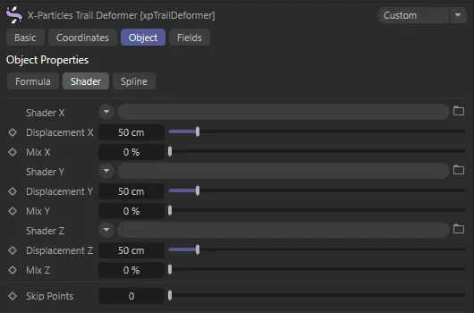
xpTrailDeformer Shader tab menu settings.
Shader X, Shader Y, Shader Z
Section titled “Shader X, Shader Y, Shader Z”The shaders to use for shader-based displacement of a point.
An empty link field will have no effect on the point.
The shader is sampled for each point on the trail spline; typically this will return a value between 0 and 1 for each point.
Displacement X, Displacement Y, Displacement Z
Section titled “Displacement X, Displacement Y, Displacement Z”The amount of displacement generated by the shader along each axis.
This is multiplied by the result of sampling the shaders to find the actual displacement of a point.
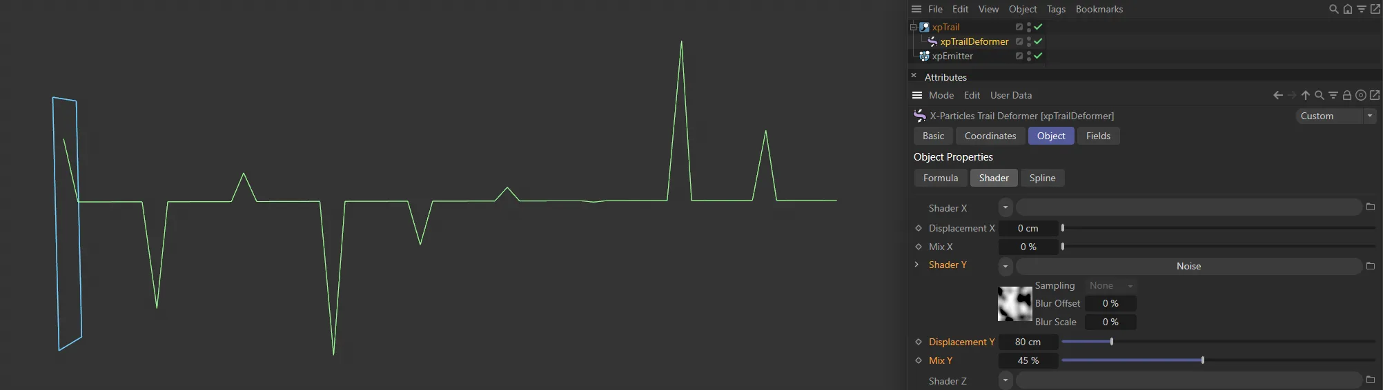
In this image, a Noise shader has been added to Shader Y, adding deformation to the spline. There is also an 80cm Displacement Y value set.
Mix X, Mix Y, Mix Z
Section titled “Mix X, Mix Y, Mix Z”The contribution to the displacement made by the formulas and shaders.
A value of 0 (zero) % means that all the displacement is generated by the formulas; a value of 100% means that the shaders control the displacement and the formulas have no effect.
Spline tab
Section titled “Spline tab”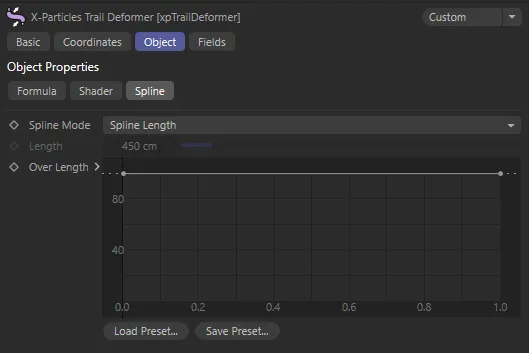
xpTrailDeformer Spline tab menu settings.
Spline Mode
Section titled “Spline Mode”Set as Spline Length, by default, you can also control the displacement over the length of the spline with the spline controls.
This enables you to do things such as having no displacement at the start of the spline and maximum displacement at the end; with a sine wave formula this gives a tentacle-like effect.
The spline works by multiplying the calculated displacement from the formulas and/or shaders by the value from the spline control; this value in turn depends on the relative position of a trail spline point along the length of the trail spline.
The first point on the trail spline will always use the value from the extreme left of the control spline.
For all points on the trail spline, the value obtained from the control spline in the interface depends on the relative position of the point along the trail length.
Since the trail may get longer over time, the length can be regarded in one of two ways.
If the Spline Mode parameter is set to the alternative setting of Fixed Length then the relative position of each point is calculated according to the value in the Length parameter.
For example, if Length is set to 450 units and a point on the trail spline is located at 150 units from the start of the trail, the point has a relative value of 150/450 = 0.333.
This is then used to read the value from control spline.
If Spline Mode is set to the default, Spline Length, then the actual length of the trail spline is used.
So if, at a specific time, a point on the trail spline is 50 units from the trail start and the length of the trail at that point is 100 units, the relative position is 50/100 = 0.5.
But, if after some more time has elapsed, the trail length is now 200 units, the relative position of the point will have changed - it is now 50/200 = 0.25.
Different effects will result from these two modes.
Length
Section titled “Length”The fixed-length value to use when Spline Mode is set to Fixed Length.
Over Length
Section titled “Over Length”The actual control spline, as explained above.
Copyright © 2026 INSYDIUM LTD. All rights reserved.