xpDynamics
This tag adds object dynamics capabilities to X-Particles.
This means you can use other X-Particles objects, such as particle modifiers and collision tags to move an object and implement collisions.
The xpDynamics tag will generate particles - ‘dynamic’ particles - which are created on the vertices of an object, on a polygon surface or in an object’s volume.
These different modes have different uses, depending on the nature of the simulation.
The particles are ordinary particles except that they remain stuck to the object they are controlling.
Once they are generated, they can be affected by modifiers in the usual way, eg, they will fall if a gravity modifier is added to the scene.
This is important if you subsequently test the speed of these particles in some way; you might assume their speed is that shown in the emitter, but that is not the case.
Their speed depends on whatever is done to start them moving, such as a gravity or turbulence modifier.
Using the tag is very simple.
First, add the tag to the object to be moved by the dynamics system.
When you play the animation, particles are emitted and attached to the object but nothing else will happen, because there is nothing to move the particles; you need to move the particles to move the object.
Next, add a xpGravity modifier and when you play the animation, the particles fall downwards, taking the object with it.
Optionally, add a collider object to act as a floor and attach an xpCollider tag.
Now when the particles attached to the falling object hit the floor object, they will bounce, and so will the object.
But, if you want more control over the particles, you can create an emitter and add it to the Emitter link field.
You should also note that you cannot move an object using keyframes and X-Particles dynamics at the same time; results are unpredictable if you try.
Tag tab
Section titled “Tag tab”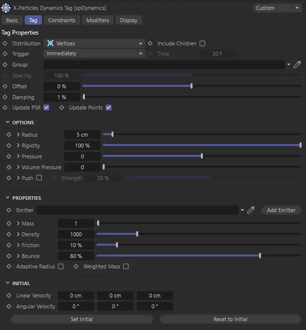
xpDynamics Tag tab menu settings.
Distribution
Section titled “Distribution”Set as Vertices, by default, this menu controls how the particles are distributed on the object.
The other options are: Vert + Mid, Surface and Volume.
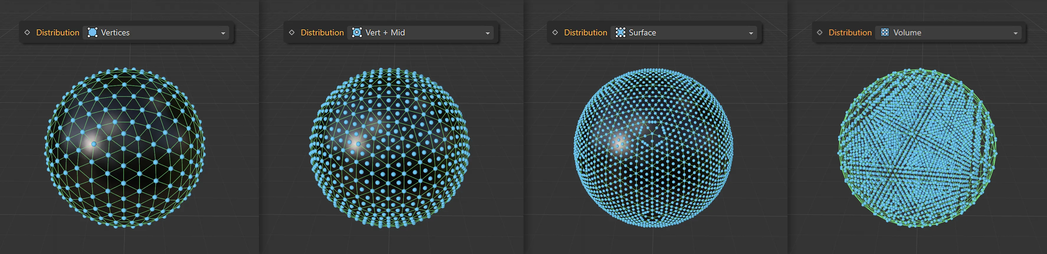
The Distribution modes of Vertices, Vert + Mid, Surface and Volume (from left to right).
Vertices
Section titled “Vertices”A particle is added to each object vertex.
Vert + Mid
Section titled “Vert + Mid”A particle is added to each object vertex, plus one in the center of each polygon.
Surface
Section titled “Surface”Particles are distributed over the object surface.
Volume
Section titled “Volume”Particles fill the object’s volume.
Include Children
Section titled “Include Children”If this box is checked, child objects of the object with the xpDynamics tag are also included.
Trigger
Section titled “Trigger”Set as Immediately, by default, this menu determines when the dynamics become active, when the particles required for the dynamics system are generated.
The alternative setting is At Time.
Immediately
Section titled “Immediately”The particles are generated as soon as the animation plays.
At Time
Section titled “At Time”The particles are generated at the time specified in the Time setting.
Only available if Trigger is set to At Time, It is the scene time when the particles required for the animation will be generated.
If you drag a particle Group object into this field, the generated particles will belong to this group.
The particles will always be drawn in the Squares display type but will use the group’s color.
The purpose of this parameter is to give more control from modifiers, actions and other objects over the particles used in the dynamics simulation.
Spacing
Section titled “Spacing”Only available if Distribution is set to Surface or Volume, this parameter controls the spacing between particles covering or filling the object.
This value will affect the number of particles which are generated and changing it will affect the rigidity of the object.
The value in the Radius setting is multiplied by this value to determine the spacing.
If Radius is 5 scene units and Spacing is 100%, the space between particles is 5 units.
If Spacing is 200%, the space will be 10 units and so on.
This setting enables you to maintain the radius at the required value while independently altering the space between particles.
Offset
Section titled “Offset”This parameter moves the particle along the surface normal, either away from the object (positive values) or into the object (negative values).
The value in the Radius setting is multiplied by this value to determine the actual offset (as explained above).
Damping
Section titled “Damping”This is normally set at a very low level.
Increasing it will reduce the strength of the dynamic constraints, including rigidity strength.
Sometimes a constraint can oscillate, so increasing this setting will reduce the constraint strength and help to reduce oscillation.
Update PSR
Section titled “Update PSR”If this box is checked, the position, scale and rotation (PSR) of the object will be altered as the particles are updated.
If it is unchecked, the object will move with the particles but its PSR values will not change from their initial state.
Update Points
Section titled “Update Points”If this box is checked, the vertices of the object are updated as the particles are updated.
If you uncheck it, the particles and the object move but the object does not deform, giving a more rigid look.
Options
Section titled “Options”Several of the parameters have a little arrow next to them.
Clicking this arrow will reveal a link field labelled Map.
You can drag a selection tag or a vertex map into this field.
This will then be used to alter the corresponding setting for particles on vertices depending on whether the vertex is included in the selection (or on the vertex weight, if a vertex map is used).
Radius
Section titled “Radius”This is the radius of the generated particles.
It overrides the radius value in any emitter you may supply in the Emitter field.
Rigidity
Section titled “Rigidity”A value of 100% means that the particles are forced to retain the shape of the object.
If the value is less than 100%, they are freer to move from their position and the result appears softer.
The more constraints you have (i.e. the more particles you have), the more iterations are required.
You can alter the number of iterations in the X-Particles project settings.
In this animation, Rigidity is set at 1% on the left and raised to 25% on the right.
Pressure
Section titled “Pressure”This is the pressure applied to the vertices of an object, in the direction of the surface of the object, so it can be used to inflate or deflate an object (if it has a volume).
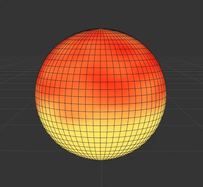
Image to display the vertex map which is being used in the animation on the right. There is a brightness set towards the bottom and an overlaid noise.
Using the vertex map on the left (dropped into the Map field) and the Pressure value at 200, the resulting sim expands the soft body mesh on the bottom, while the brighter parts of the noise create a rippled surface over the top of the Sphere.
Volume Pressure
Section titled “Volume Pressure”Increasing this value applies pressure to try to maintain the volume of the object.
For example, if an object is squashed between two other objects, it will inflate vertically to maintain the volume.
In this first scene, the Sphere has 0 (zero) % Volume Pressure set and is easily displaced by the impact of the Cube.
With the Volume Pressure raised to 3, the volume is stable throughout and when the impact occurs, the right side of the Sphere inflates.
If checked, additional constraints are added to push the particles apart.
This can impart a jelly-like movement to the object on collision, to help keep particles away from one another, which can assist in preventing intersections in the mesh.
Strength
Section titled “Strength”Only available if Push is checked, this is the strength of the effect.
Properties
Section titled “Properties”Emitter
Section titled “Emitter”You can drag an emitter into this link field.
This is optional, since the tag will create the required particles if an emitter is not given.
Adding an emitter to this field gives you greater control over the particles (for example, it would allow you to specify which modifiers in the scene work with this emitter, which you cannot do with the emitter built in to the tag).
Add Emitter
Section titled “Add Emitter”Click this button to create a new emitter and add it to the Emitter field.
Mass, Density, Friction, Bounce
Section titled “Mass, Density, Friction, Bounce”These are the corresponding particle properties found in the emitter.
They are set by the values in these settings instead of by the emitter itself.
Adaptive Radius
Section titled “Adaptive Radius”If checked, the particle radius is adjusted according to the size of surrounding polygons, so small polygons give small particle size.
Weighted Mass
Section titled “Weighted Mass”If checked, the particle mass is adjusted according to the size of surrounding polygons, so small polygons give small particle mass.
Initial
Section titled “Initial”Linear Velocity
Section titled “Linear Velocity”You can use this parameter to give some initial velocity to the object along any of the desired axes.
This doesn’t require a particle modifier.
The particles are given the required speed and direction; the speed is given in terms of scene units per second.
For example, if the X component had a value of 100 scene units and Y and Z were both zero, the particle speed would be 100 units per second with a direction vector of (1, 0, 0) - that is, along the positive X axis.
With Linear Velocity at 350cm on the Y axis and 400cm on the Z axis, the Cube in this scene has an initial velocity set.
Angular Velocity
Section titled “Angular Velocity”As with Linear Velocity, you can use this parameter to give some initial spin to the object around any of the desired axes.
This doesn’t require a particle modifier.
The values are shown as degrees of rotation per second.
In this animation, the Angular Velocity is set to 35 degrees on both the heading and the pitch, resulting in an initial spinning velocity,
Set Initial
Section titled “Set Initial”Click this button to set the initial state of the object.
To move the object, either do so on the starting frame of the scene (before the tag has generated any particles) or disable the tag first, then move the object.
Reset to Initial
Section titled “Reset to Initial”Resets the object to its initial state.
Constraints tab
Section titled “Constraints tab”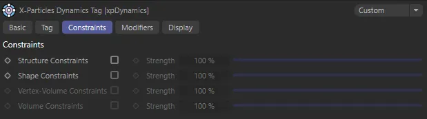
xpDynamics Constraints tab menu settings.
This tab enables you to apply certain constraints to the particles which affect the object’s rigidity.
In each case, the Strength parameter is only available if the corresponding box is checked, to enable the constraint, and the Strength value controls the strength of the corresponding constraints.
Structure Constraints, Strength
Section titled “Structure Constraints, Strength”These are constraints between polygon edges or spline vertices.
The following three animations have been set up with low rigidity so that the Wolf is a very soft dynamic object. In this first scene with Structure Constraints at 5%, there is some instability in the simulation and a drastic deformation of the mesh.
With Structure Constraints increased to 100, in this second animation, the mesh is more able to retain its structure.
Shape Constraints, Strength
Section titled “Shape Constraints, Strength”These constraints are set across polygons or across every other spline point.
Finally, with Shape Constraints enabled, the soft body dynamic object achieves additional support in retaining its initial likeness.
Vertex-Volume Constraints, Strength
Section titled “Vertex-Volume Constraints, Strength”Only available when Distribution is set to Volume.
Constraints are then added between each vertex and the closest particles in the object volume.
Volume Constraints, Strength
Section titled “Volume Constraints, Strength”Only available when Distribution is set to Volume.
These constraints link the entire object together, giving a more rigid volume.
Modifiers tab
Section titled “Modifiers tab”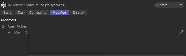
xpDynamics Modifiers tab menu settings.
This tab contains a list of particle modifiers acting on the emitter used by the xpDynamics tag.
You can use it either to prevent certain modifiers from acting on the emitter or for specifying that only certain modifiers do so.
Drag any modifiers you want to affect into this list.
If the modifier has a yellow check icon, it will act on the emitter; if it has a blue dash icon, it will not do so.
Same System
Section titled “Same System”If this box is checked, only modifiers which are child objects of the same System object as the emitter used by the tag will be excluded or included.
Modifiers
Section titled “Modifiers”The list of modifiers to be excluded or included.
Display tab
Section titled “Display tab”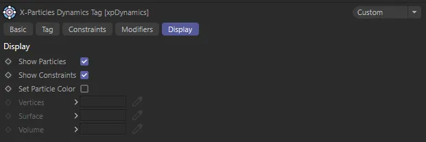
xpDynamics Display tab menu settings.
This tab enables you to alter the visibility and color of the particles and/or constraints.
Show Particles
Section titled “Show Particles”If checked, the dynamics particles are shown in the viewport.
Show Constraints
Section titled “Show Constraints”If checked, any constraints are shown in the viewport.
Set Particle Color
Section titled “Set Particle Color”Checking this box will allow you to change the colors used for the particles.
Vertices, Surface, Volume
Section titled “Vertices, Surface, Volume”These are three color settings which control the colors used for particles located at the object’s vertices, on the surface and inside the object volume.
Copyright © 2026 INSYDIUM LTD. All rights reserved.