xpCollider
The xpCollider Tag forms part of the collision engine used in X-Particles.
In order to test for collision between a particle and a scene object, the scene object must have an instance of this tag attached to it.
General tab
Section titled “General tab”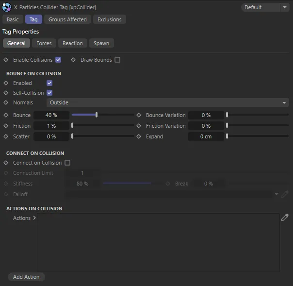
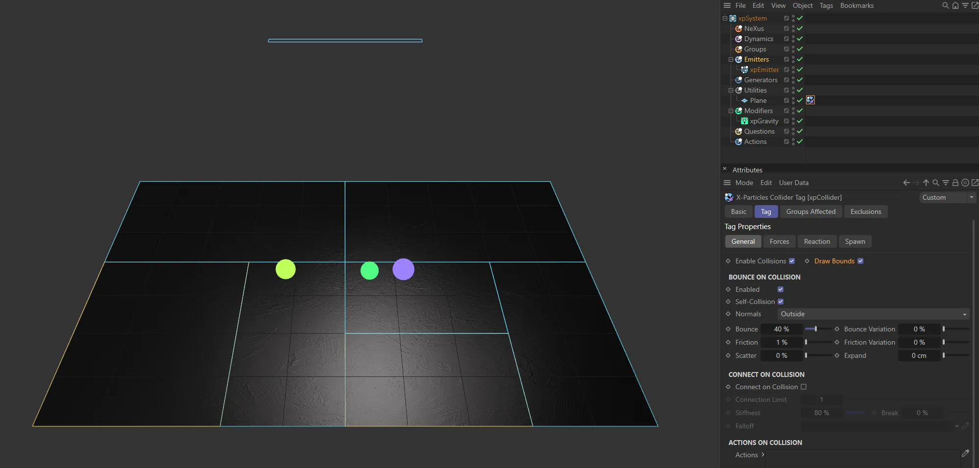
xpCollider Tag General tab menu settings.
Enable Collisions
Section titled “Enable Collisions”If this is unchecked, the object to which the tag is attached will not be checked for collisions with any particles.
Animation to demonstrate how simple it is to attach an xpCollider Tag and the immediate effect.
Draw Bounds
Section titled “Draw Bounds”The collision engine in this version of X-Particles uses adaptive bounds for the collisions.
Instead of testing every polygon in an object to see if a particle is colliding with it, the engine only tests relevant areas of the mesh.
It does this by dividing the mesh into smaller and smaller boxes until the area containing the correct polygon is found.
You can show the adaptive boxes as they are created by enabling this setting.
This can be useful if you have multiple colliders and you aren’t sure if particles are colliding with one of them.
Draw Bounds enabled, showing the adaptive bounds on the mesh area for the collisions.
Bounce On Collision
Section titled “Bounce On Collision”Enabled
Section titled “Enabled”For particles to bounce from the collider object, check the Enabled box in this section.
If this is unchecked, no bounce will occur but the collision will still be registered. (If you have an action which is triggered by a collision, it will be triggered even if this is unchecked.)
Self-Collision
Section titled “Self-Collision”This option is used when emitting from an object which has a collider tag attached to it.
If enabled (the default setting) then the emitted particles will collide with the object from which they are emitted.
If it is disabled, they will not collide with it.
This is useful, for example, when you want to attach a collider tag to an xpCloth object.
Unchecking this box will prevent the particles which are emitted from the cloth object from colliding with the cloth, stopping the simulation from working correctly.
Other particles, of course, will still collide with the cloth.
This animation shows the effect with Bounce On Collision option enabled.
Normals
Section titled “Normals”Set as Outside, by default, there are two other options: Inside and Any.
In this animation, the Normals parameter is illustrated, first set at Outside, then changed to Inside.
Outside
Section titled “Outside”Normals on objects tend to point outside of the object, so the interior of the object should be the opposite direction of the normal.
With this setting, any particle found ‘inside’ the object (by using the normals) is pushed out.
Inside
Section titled “Inside”Sometimes you want to keep particles inside the objects (e.g. particles in a cube); with this setting, particles found ‘outside’ are pushed out.
If you want to ignore the inside/outside and just go for the particle hitting the polygons, then this is the setting.
Bounce, Bounce Variation
Section titled “Bounce, Bounce Variation”The Bounce setting controls the speed with which the particle will rebound from the object.
A bounce of 100% means that the speed after hitting the object is the same as before hitting it.
You can add some random variation to the amount of bounce with the Bounce Variation setting.
This animation shows the effect of the Bounce and Bounce Variation parameters.
Friction, Friction Variation
Section titled “Friction, Friction Variation”These settings add friction between the particle and colliding surface.
Friction will cause rolling particles to come to a halt.
The higher the setting, the more quickly they stop.
You can add some random variation to the amount of friction with the Friction Variation setting.
Animation to demonstrate the Friction setting, first at 1%, then raised to 100%.
Scatter
Section titled “Scatter”When bouncing from a flat surface, the particles will rebound at a reflected angle, which is correct for the angle at which the particle strikes the surface.
For example, if the particle hits the surface at an angle of 90 degrees to it, the particle will bounce back in a direction which is the exact reverse of its original course.
This is geometrically correct but not necessarily realistic.
The Scatter parameter causes a degree of spread or scatter when the particle stream rebounds from a surface.
Raising the Scatter value from 0 (zero) % to 20% has a dramatic effect, as shown in this animation.
Expand
Section titled “Expand”The distance between the particle and the collider object at which the collision occurs is determined by the particle radius.
This is not always appropriate for some surfaces - the particle may get too close to the surface before colliding.
This setting is used to increase the collision radius and can be applied on a per-object basis.
Radius
Section titled “Radius”This setting is only available if the tag is attached to a spline object.
Particles can then collide with splines without needing to create geometry to detect collisions.
This setting is the distance around the spline where collisions will occur.
If the particle is farther away from the spline than this distance, there will be no collision.
Connect on Collision
Section titled “Connect on Collision”Connect on Collision
Section titled “Connect on Collision”If this is enabled, connections may be made between the particle and the collider object.
You may not see any, if the nature of the collisions, friction, bounce, etc. mean that the connection can never be made, or breaks immediately after it is made.
Enabling the Connect on Collision setting will work, even with Bounce and Scatter values set, as demonstrated here.
Connection Limit
Section titled “Connection Limit”The maximum number of connections a particle may make to a collider object.
Stiffness
Section titled “Stiffness”This controls how ‘strong’ the connection effect is.
Animation to demonstrate the effect of lowering the value of the Stiffness parameter.
A measure of how much the connection can stretch before it breaks.
0 (zero) % means that the connection will never break.
50% means that it will break when it has stretched to 50% of its original length.
Falloff
Section titled “Falloff”Dragging a vertex map into this field will alter the connection stiffness.
Maximum stiffness will apply where the vertex weight is 100% and will not apply at all if the weight is 0 (zero) %.
Actions on Collisions
Section titled “Actions on Collisions”Actions
Section titled “Actions”You can drag one or more actions into this list and those actions will be carried out on each particle when it collides with the object.
You can use any Action object you like.
The action is triggered directly by the collision - in effect, the collision event acts as a question which triggers an action.
This animation demonstrates the addition of an action, using the Add Action button, then using the Editor Display to make that action, the change of particles, on collision, to the Display mode of Circle.
Add Action
Section titled “Add Action”Clicking this button will add an action to the scene and drop it into the Actions list.
You can still modify the speed on collision by using the xpSpeed modifier instead of an action; set the modifier to be action-controlled then add an action to enable the modifier for a particle when it collides.
Forces tab
Section titled “Forces tab”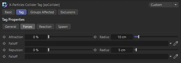
Forces tab settings menu.
Attraction and Radius
Section titled “Attraction and Radius”This represents an attraction force between the particle and the collider.
You can set the force strength in the Attraction parameter.
The particle must be as close or closer to the collider object than the value given in the Radius setting before the force will have any effect.
Animation demonstrating the effect of increasing the Attraction value, on collision from 0 (zero) % to 30%.
With Attraction set at 100%, this animation shows the effect of increasing the Radius value, on collision, from 10cm to 65cm.
Repulsion and Radius
Section titled “Repulsion and Radius”This represents a repulsion force between the particle and the collider.
You can set the force strength in the Repulsion parameter.
The particle must be as close or closer to the collider object than the value given in the Radius setting before the force will have any effect.
Here, on collision, the Repulsion setting is at 100%, for particles being closer to the collider object than the Radius setting of 50%.
Falloff
Section titled “Falloff”By default particles are attracted to (or repulsed from) the whole mesh, subject to the Radius settings.
If you want the force to apply to only part of the mesh, drag a vertex map into the Falloff link field.
Maximum force will apply where the vertex weight is 100% and will not apply at all if the weight is 0 (zero) %.
Reaction tab
Section titled “Reaction tab”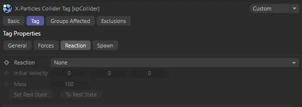
Reaction tab settings menu.
Reaction
Section titled “Reaction”Set as None, by default.
The alternative setting is Translate.
The object the particle collides with is unaffected by the collision.
Translate
Section titled “Translate”The object the particle collides with will be moved by the collision, in a direction away from the particle, after collision.
Initial Velocity
Section titled “Initial Velocity”The colliding object can be given an initial velocity on the X, Y or Z-axes with this control.
With an Initial Velocity of 125 on the Y-Axis, the Sphere is moving towards the particles at this velocity until the collision arrests this movement.
This is the mass of the object.
The lower the mass, the more effect the Translate mode has on particle collision.
In this animation, with a Mass value of 5, there is the same exact set up as above, except the Sphere’s Mass value is significantly reduced from 100. As a result, the particles are pushing the Sphere downwards.
Set Rest State, To Rest State
Section titled “Set Rest State, To Rest State”If you add an xpCollider tag to an object and set Reaction to Translate you may find that, if you move the object and the play the scene, the object jumps back to the position it was in before it was moved.
To fix the initial position of the object, click Set Rest State.
To move an object to its initial (rest) state, click To Rest State.
Spawn tab
Section titled “Spawn tab”The collision engine can spawn new particles on collision.
You don’t need a spawn modifier or action to do this; the collision engine triggers the spawning directly.
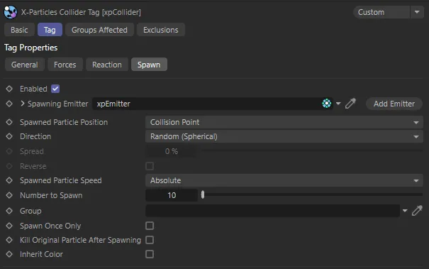
Spawn tab settings menu, with an xpEmitter dropped in the Spawning Emitter parameter.
Enabled
Section titled “Enabled”This must be enabled before spawning takes place.
Spawning Emitter
Section titled “Spawning Emitter”Drag an emitter into this field; this emitter will be used to generate the new particles.
When you drag an emitter into this field, the Emission Mode setting in that emitter will automatically be set to Controlled Only.
Add Emitter
Section titled “Add Emitter”Click this button to create a new emitter and add it to the Spawning Emitter field.
Animation to demonstrate the effect of adding a spawning emitter to the scene, with Spawned Particle Position being set to Collision Point.
Spawned Particle Position
Section titled “Spawned Particle Position”Set as Collision Point, by default, this drop-down determines where the particle will be emitted.
The alternative is Determined by Emitter.
Collision Point
Section titled “Collision Point”The spawned particles will be emitted from the point of collision.
In this mode, the direction of the spawned particles is determined by the Direction setting.
Determined by Emitter
Section titled “Determined by Emitter”In this mode the spawning emitter decides where the particles are emitted.
It is possible to have the spawning emitter emit particles from an object which may be at a completely different position from where the collision occurred.
The spawning emitter also determines the direction of the spawned particles.
This animation shows the Spawned Particle Position set as Determined by Emitter.
Direction
Section titled “Direction”Set as Random (Spherical), by default, this is how the direction of the spawned particles is determined.
It is only available if Spawned Particle Position is set to Collision Point.
The other options are: Source Particle and Face Normal.
Random (Spherical)
Section titled “Random (Spherical)”The direction of the spawned particles is set to a random value which, in practice, means that the spawns adopt a spherical distribution.
Source Particle
Section titled “Source Particle”In this mode, the direction of the new particle is the same as the source particle (but can be modified by the Spread and Reverse settings).
Face Normal
Section titled “Face Normal”In this mode, the direction of the new particles is along the normal of the face the source particle collided with.
The direction can be modified by the Spread and Reverse settings.
Spread, Reverse
Section titled “Spread, Reverse”These parameters are only available if Spawned Particle Position is set to Collision Point and the Direction parameter is set to Source Particle or Face Normal.
You can modify the directions of the spawned particles with these parameters.
Spread is a deviation to the particle heading, in percentage terms, from the direction of the source particle.
At a low value of 10%, this causes the spawns to follow a narrow cone along the path of the source particle; set to 100%, you will get a hemisphere of particles.
The Reverse setting, if enabled, will reverse the direction of the spawned particles so that, instead of following along the path of the source particle, they head directly away from it.
In this animation, the Spread value is increased from 0 (zero) % to 25%, producing a hemispheric spread of particles.
Spawned Particle Speed
Section titled “Spawned Particle Speed”Set as Absolute, by default.
The alternative setting is Relative.
Absolute
Section titled “Absolute”With this option, the spawned particles will have the speed given in the spawning emitter.
Relative
Section titled “Relative”If you select this option, the speed in the spawning emitter is added to the current speed of the source particle.
For example, if the spawning emitter has a speed of 50 and the source particle has a speed of 150, the new particles will have a speed of 200 (150 + 50).
Animation to demonstrate Spawned Particle Speed set as Relative, increasing the speed of the spawned particles.
Number to Spawn
Section titled “Number to Spawn”This is the number of particles to be spawned from the source particle.
This enables you to specify the group to which the spawned particles will belong.
If there is nothing in this field, the group is determined by the spawning emitter.
To specify the group, drag the desired Group object into this field.
This setting is useful if you want to ensure that the spawned particles are, or are not, affected by a specific modifier.
Spawn Once Only
Section titled “Spawn Once Only”If this is enabled, the tag will only spawn once from a specific particle.
This is to prevent multiple spawning from a particle which is repeatedly colliding with the collider object, for example, under the influence of a gravity modifier.
In this animation, Spawn Only Once is activated, preventing multiple spawning.
Kill Original Particle After Spawning
Section titled “Kill Original Particle After Spawning”If enabled, this will remove the source particle from the scene, after it has spawned.
This can be used to ensure that each source particle spawns only once.
With Kill Original Particle After Spawning enabled, the source particle is killed immediately after spawning.
Inherit Color
Section titled “Inherit Color”The spawned particles will inherit the color of the source particle.
Animation to show how spawned particles inherit the color of the source particle with Inherit Color enabled.
Groups Affected tab
Section titled “Groups Affected tab”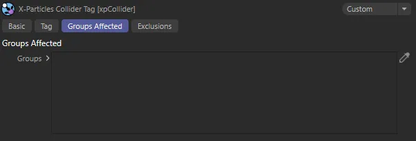
Groups Affected tab menu.
Groups
Section titled “Groups”Drag the particle Group object(s) you want to be affected by the tag into the Groups list.
If the list contains at least one group, groups not in the list will not be affected by the xpCollider tag.
If no groups are in the list, all groups are affected.
Exclusions tab
Section titled “Exclusions tab”By default, the xpCollider tag will look for collisions with particles emitted from all the emitters in the scene.
It might happen that you don’t want to detect collisions with particles from a particular emitter, but you do want that emitter’s particles to collide with other objects (so you can’t simply disable collisions in the tag or the emitter).
Alternatively, you might want to specify that only certain emitters will collide with this object.
You can use this tab to do either of these actions.
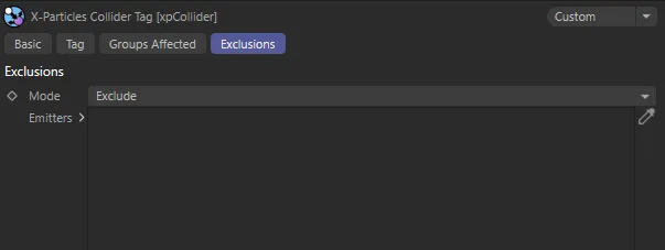
Exclusions tab menu.
Set as Exclude, by default.
The alternative setting is Include.
Exclude
Section titled “Exclude”In this mode, if you drag the emitter(s) into the Emitters list, collisions will not be detected for this object and any emitters in the list.
Include
Section titled “Include”The opposite of Exclude; only particles from emitters in the Emitters list will collide with the object.
With all other emitters, no collisions will take place.
Emitters
Section titled “Emitters”The list of emitters to exclude from or include in collisions.
Copyright © 2026 INSYDIUM LTD. All rights reserved.