xpCloth
The Cloth Tag is the main controller of an object which is to be used as cloth.
If the object does not have a Cloth Deformer as a child object, the tag should be attached directly to the object.
If there is a deformer, the tag should be on that deformer rather than on the object itself.
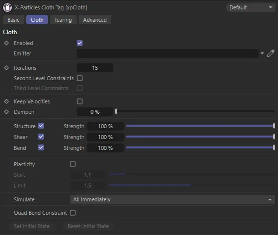
xpCloth Tag Cloth tab menu.
Enabled
Section titled “Enabled”Lets you start the simulation at a specific frame.
The cloth is still initialized on the start frame so it will not take on the shape of any deformations that occur from the start frame until this option is enabled.
This option can also be used to stop the simulation.
Emitter
Section titled “Emitter”A link to the xpEmitter.
An appropriate emitter will automatically be created when you click on the Create Cloth command, when either a Polygon Object is selected or a Cloth Deformer is selected.
The Create Cloth command will also add a cloth tag and set this emitter for you if there is not a cloth tag already set.
Iterations
Section titled “Iterations”Sets the number of times the cloth simulation is run each time step.
A higher number produces a more rigid cloth, like sheet metal, while a lower number will produce a very soft, flexible cloth simulation.
Iterations set at a value of 5.
Iterations value raised to 15.
In this final image, with Iterations at 55, there is a more accurate and rigid cloth sim.
Second Level Constraints
Section titled “Second Level Constraints”This will add additional constraints to every point that is ‘2 points’ away from the start point.
Third Level Constraints
Section titled “Third Level Constraints”This will add additional constraints to every point that is ‘3 points’ away from the start point.
Keep Velocities
Section titled “Keep Velocities”If this box is unchecked (the default setting), the particle velocity will be altered by the cloth modifier to improve the cloth behaviour when the particles move.
If it is checked, the particle velocity is unaltered, so they have the velocity they would have had in the absence of the cloth effect.
This can produce a different appearance, which may, or may not, be desirable.
Dampen
Section titled “Dampen”This setting (which is not available if Keep Velocities is checked) will dampen the forces applied to the particles by the cloth modifier.
You can use it to smooth out the particle movement, but at high values you will see little or no movement at all.
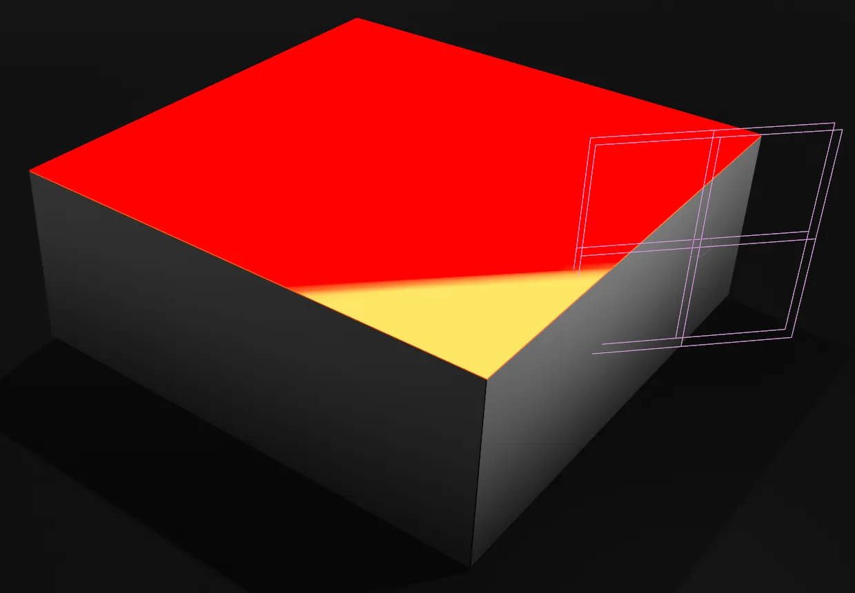
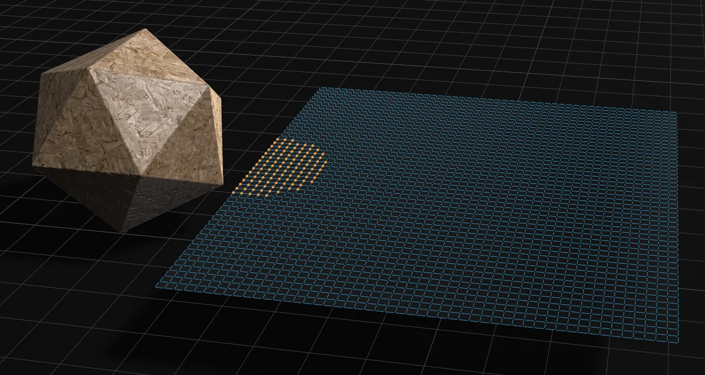
Structure, Strength
Section titled “Structure, Strength”Create constraints to the left, right, top and below a given point on the mesh.
Strength sets how strong the constraint is; the lower the value, the less effect this constraint has.
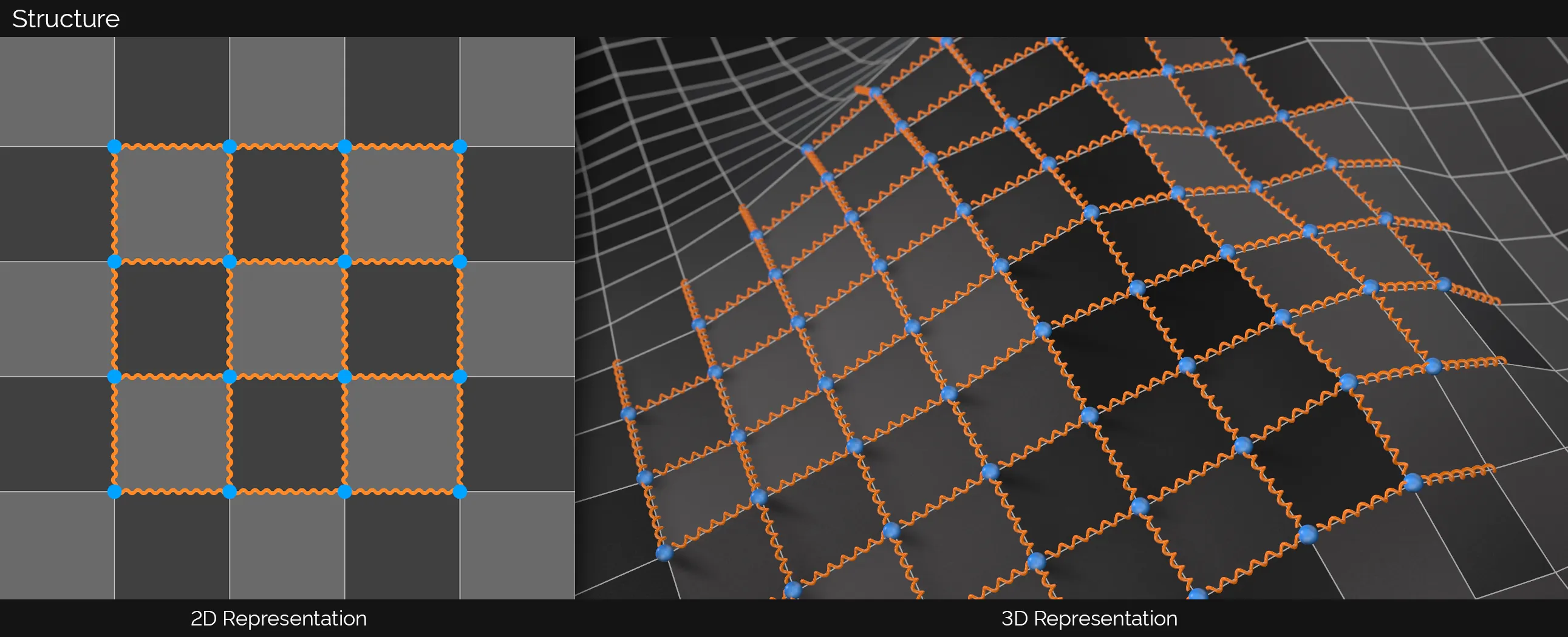
Here, you can see a 2D and a 3D representation of Structure dynamic constraints. The orange spheres signify the vertex positions where the spring-like constraints start and end. For Structure, this is to the left, right, top and below a given point.
Animation to demonstrate the Structure setting, with the Strength slider. With a lower Strength setting in the cloth sim on the right, the quads are able to become enormously relaxed. This is most visible in the top and bottom row of polygons; with a very low value, the springy constraints allow the quads to almost collapse.
Shear, Strength
Section titled “Shear, Strength”Create constraints from the top-left to the bottom-right and the top-right to the bottom-left on each individual quad.
Strength sets how strong the constraint is; the lower the value, the less effect this constraint has.
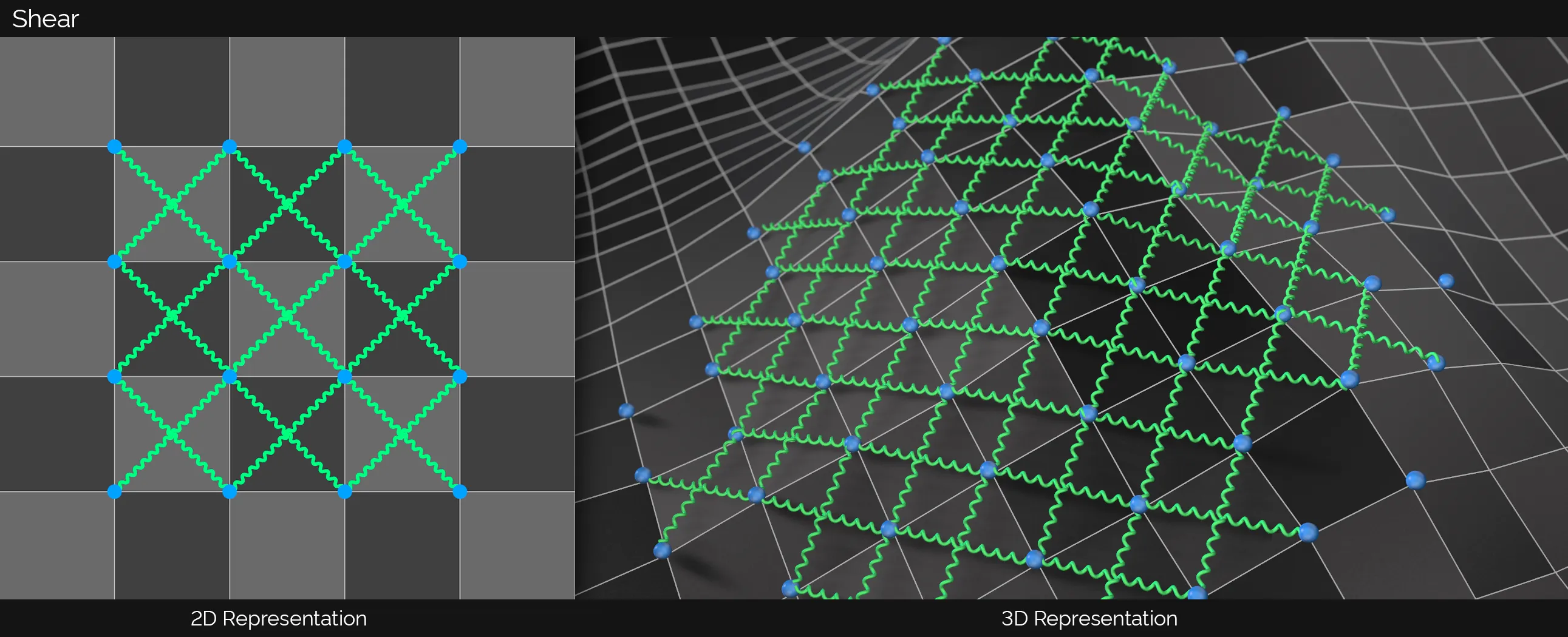
In this image, there are 2D and 3D representations of Shear dynamic constraints. The orange spheres signify the vertex positions where the spring-like constraints start and end. For Shear, this is from the top-left to the bottom-right and from the top-right to the bottom-left on each individual quad.
This animation demonstrates the Shear setting, with the Strength slider. With a lower Shear setting in the cloth sim on the right, the cloth is able to stretch along its axis, even with minimal forces acing upon it, resulting in a much more vertical sagging towards the middle of the cloth.
Bend, Strength
Section titled “Bend, Strength”Create constraints 2 points away upwards, below, to the left and right of a point.
Strength sets how strong the constraint is; the lower the value, the less effect this constraint has.
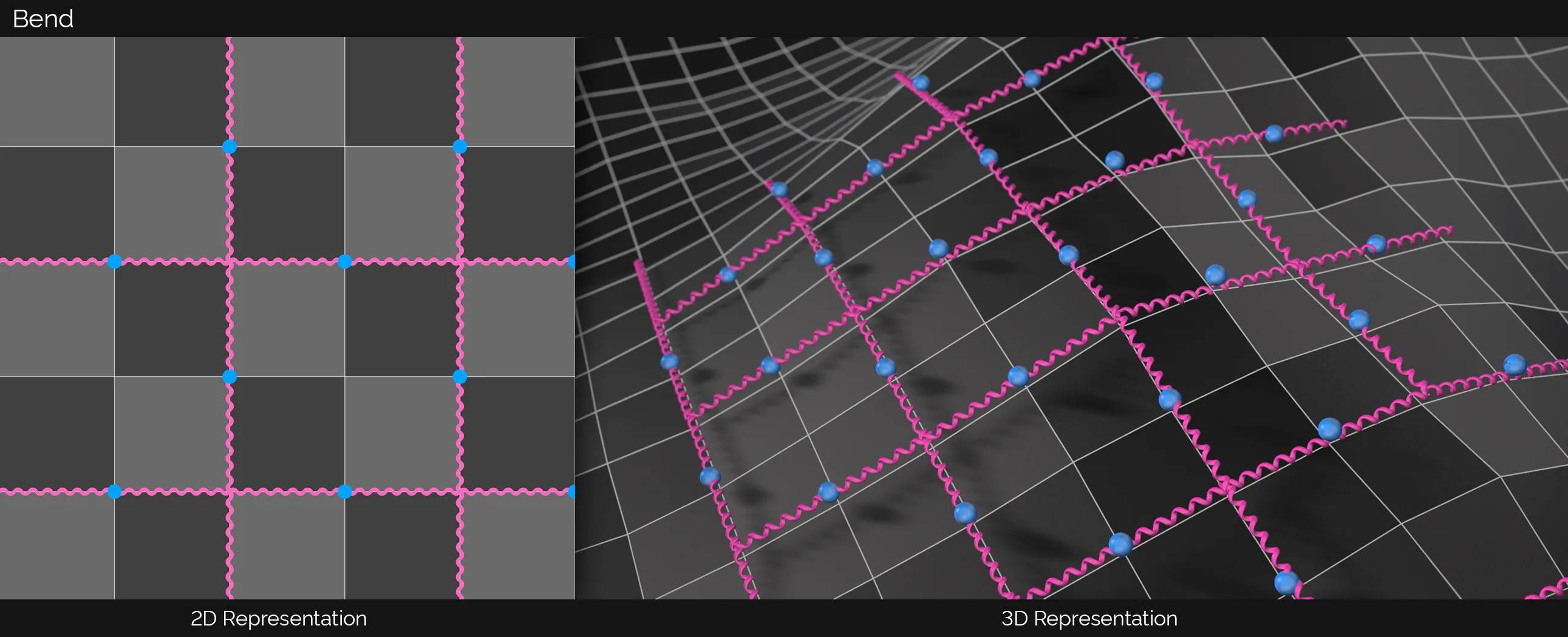
This image shows 2D and 3D representations of the Bend dynamic constraints. The orange spheres signify the vertex positions where the spring-like constraints start and end. For Bend, this is two points away upwards, below, to the left and to the right of a point.
In this animation, there is a demonstration of the Bend setting, with the Strength slider. With a lower Bend setting in the cloth sim on the right, the cloth is able to bend, fold and crease with ease when compared to the simulation on the left.
With the Strength for all three options (Structure, Shear and Bend) set at 100%, in this animation, the cloth naturally finds its way back to a flat form.
In this second scene, the Strength remains high for Shear but is dropped low for both Structure and Bend, giving more definition during the twisting, while maintaining the relaxed, natural look and ending up flat, once again.
This final animation demonstrates the effect of low Strength settings for all three options. This results in a very flimsy cloth, which hardly retains its form, however, the detail remains in the folds and wrinkles at the end of the animation.
Plasticity
Section titled “Plasticity”Cloth is normally springy when pinned and, when something collides with it, it tends to return to its original shape.
If this box is checked, the cloth becomes plastic in nature and once deformed it remains that way.
Plasticity is enabled in this animation, with a Start setting of 1.045 and a Limit of 1.5. This ensures that impressions are left in the plastic-like surface from particle collisions.
This is a measure of how much force must be applied to cause the plasticity effect.
If you set this too high, you will not see any plasticity and either it must be reduced or the force increased (for example by increasing the colliding object or particle’s speed) to see the effect.
If it is too low, the plasticity effect may be excessive; you can correct that by increasing this value or reducing the force.
This is the maximum plastic effect that will be generated.
It must be higher than the Start value to see any effect.
The greater the difference between Start and Limit, the greater the effect will be.
Simulate
Section titled “Simulate”Set as All Immediately, by default.
The other options are: All On Collision and Collided Points Only.
All Immediately
Section titled “All Immediately”Simulates all cloth points immediately.
All On Collision
Section titled “All On Collision”Simulates all cloth points after any collision object has hit them.
Collided Points Only
Section titled “Collided Points Only”Simulates only the cloth points that have been hit by an object.
The following options will also appear if the tag is on an xpClothDeformer.
Falloff
Section titled “Falloff”Simulate, and continue to simulate, any points touched by the falloff.
Falloff Inside Only
Section titled “Falloff Inside Only”Only simulate any points inside the falloff.
Falloff Collision
Section titled “Falloff Collision”Simulate, and continue to simulate, any points that are inside the falloff and have been hit by a colliding object.
Falloff Collision Inside Only
Section titled “Falloff Collision Inside Only”Only simulate any points that are inside a falloff and have been hit by a colliding object.
Quad Bend Constraint
Section titled “Quad Bend Constraint”This option will allow you to define how rigid the quad should be on the cloth.
This is most noticeable on low polygon objects, but can be used on higher density cloth as well for a specific simulation look and feel.
Set Initial State
Section titled “Set Initial State”This option only becomes active when the xpCloth Tag is on an editable polygon object.
When you first add an xpCloth Tag to a polygon object, the tag makes a copy of the current state of the polygon object’s points.
If you want to change the cloth then you can either make the change to the cloth and then press the Set Initial State button or delete the xpCloth Tag, make your change and then re-add a new xpCloth Tag.
If you choose the first option then make sure you do not animate the scene when you make the changes, otherwise doing so will cause the xpCloth Tag to overwrite the change at frame 0 (zero).
This option can also be used to set a starting frame for your cloth.
You could animate the cloth up until it reaches your desired look and then press the Set Initial State button.
Clear Initial State
Section titled “Clear Initial State”This will clear the initial state.
Additionally if you delete the xpCloth Tag, the initial state will also then be cleared and the object returned to its original state.
Animation to demonstrate the use of both Set Initial State, to store the state at a given point (here at frame 90), and Clear Initial State to reset.
Tearing
Section titled “Tearing”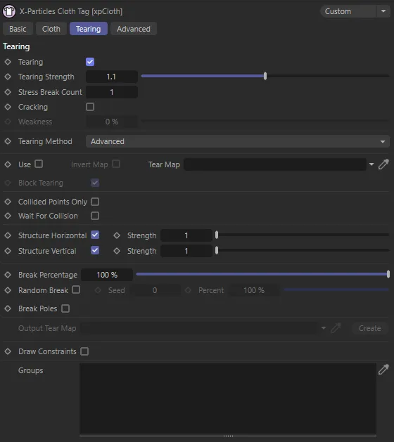
xpCloth Tag Tearing tab menu.
Tearing
Section titled “Tearing”Enables the tearing on the cloth.
Tearing is disabled in this first animation.
In this second scene, the Tearing is enabled, with a Tearing Strength of 1.1 set.
Tearing Strength
Section titled “Tearing Strength”Cloth is torn when its constraint goes past a breaking distance.
The default breaking distance is set to the distance between the two points at the start of the animation.
Adjusting this value will increase the breaking distance by multiplying it against the default distance.
You can also go negative if you wish the constraints to break immediately.
The vertex map is used to define which areas should be torn; the map is used in conjunction with block tearing to define how the cloth should be broken apart.
This animation demonstrates the Tearing Strength increased to 1.3.
The Tearing Strength has been raised further, to 1.345, in this scene.
Stress Break Count
Section titled “Stress Break Count”Tearing occurs when a constraint between particles is stressed and broken.
If you increase this value, the number of times a constraint must be stressed before it breaks is increased.
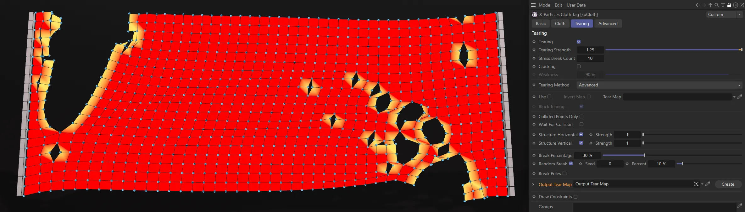
The result is that tearing first occurs in the most highly-stressed areas of the cloth.
With the Stress Break Count parameter set at 15, only the most stressed points activate the tearing.
Cracking
Section titled “Cracking”Enabling this setting will cause a crack to appear in the cloth and tearing will expand from that point.
In this animation, Cracking is enabled, with a Weakness of 50%. The tearing initiates a cracking effect that continues after the first tear occurs.
Weakness
Section titled “Weakness”This is only available if Cracking has been enabled.
It represents the strength of the constraints along the cracking edge.
The higher it is, the more likely the crack will expand.
If it is set to zero, you may not see any tearing, depending on the other parameters in the tag.
Tearing Method
Section titled “Tearing Method”Set as Advanced, by default, there are two different tearing methods that produce slightly different results depending on the look you are after.
The alternative is Simple.
Simple
Section titled “Simple”When a constraint for a point is broken, it will break away the point so that all the polygons that shared that point are now all broken off.
This method produces results where the cloth will tear itself into multiple pieces when stretched beyond its breaking limits.
It is good for destroying the cloth completely.
Advanced
Section titled “Advanced”When a constraint for a point is broken, it will look at keeping edges connected along the cloth.
Whereas Simple will just break away all the polygons, the advanced method will keep edges connected and will break away in straight lines along the breaking direction.
This method is good for breaking apart the cloth internally, to review weak spots and produce interesting tearing simulations within a cloth structure itself, without it tearing apart into smaller bits too quickly.
Will use the vertex map, or selection tags, if assigned, to restrict the tearing to specific areas of the cloth.
Invert Map
Section titled “Invert Map”Inverts the vertex map.
Tear Map
Section titled “Tear Map”The vertex map to use to define where the cloth should tear.
In this animation, with Use enabled, a vertex map has been dropped into the Tear Map field, to define where the cloth tears.
This scene shows the effect of the Edge Selection, again dropped into the Tear Map field, driving a tear along a specific path.
Block Tearing
Section titled “Block Tearing”When this option is enabled, the painted areas on the tear map will be treated as if they are solid parts of the mesh and the boundaries between painted and non-painted areas are where the cloth should tear.
With Block Tearing enabled, this vertex map is once again driving the tearing but with a different effect to the above.
If this option is disabled, then it will do the opposite and define the painted parts as the weakest portion of the cloth and break them first.
Collided Points Only
Section titled “Collided Points Only”Will only tear points that collide with an object that has an xpCollider Tag.
Wait For Collision
Section titled “Wait For Collision”Will only start the tearing detection once a collision is detected.
Structure Horizontal, Strength
Section titled “Structure Horizontal, Strength”When enabled, it will check the structure constraints that go horizontally across the surface to see if they should break.
The lower the strength, the weaker the constraint and the more likely it is to break.
Structure Vertical, Strength
Section titled “Structure Vertical, Strength”When enabled, it will check the structure constraints that go horizontally across the surface to see if they should break.
The lower the strength, the weaker the constraint and the more likely it is to break.
Break Percentage
Section titled “Break Percentage”When constraints are broken, they are ordered, from those which are most likely to break to those which are least likely, based on the amount of stress on each constraint.
By default, all constraints will break if they are stressed enough and they exceed the main Tearing Strength, set for the cloth.
By reducing this value, you can limit the number of constraints that will break with each time step.
For example, setting it to 10% will mean that only the top 10% of the highest stressed constraints will actually break; 1% will break only the top 1% of the constraints.
In this first animation, Break Percentage is set at 100%.
By direct comparison, in this second animation, with the Break Percentage value at 50%, half of the breaks are restricted.
Random Break
Section titled “Random Break”Along with the Break Percentage, you can also randomly choose a percentage of these top constraints that you want to break.
So, if Break Percentage is set to 10% and Random Break is set to 50%, then it will randomly choose 50% out of the top 10% of the constraints and only break them.
This scene has the identical settings to the last one, except Random Break is now enabled, with a Percent value of 10%. This drives a continuous breaking effect tearing through the cloth.
The seed value for the random number generator used for Random Break.
Percent
Section titled “Percent”The percentage value used if Random Break is enabled.
Break Poles
Section titled “Break Poles”Some objects, such as a Sphere, have more than four edges connected to a point; these are termed ‘poles’.
By enabling this option, all the edges at these poles will be broken as soon as any of the edge constraints are broken.
Otherwise, it may only break away one or two edges, leaving the rest intact, and they may never break apart, due to reduced stress on these locations.
Output Tear Map
Section titled “Output Tear Map”If a map is applied to this link then, anytime a point is torn, it will apply paint to this vertex map.
Create
Section titled “Create”This button will create a vertex map on the polygon object and apply it to the Output Tear Map.
This image shows a tear map. Torn areas in the mesh are used to paint the vertex map with the greatest weight.
Draw Constraints
Section titled “Draw Constraints”By using the Draw Constraints option only, with each of the individual constraint types, you can see what constraints are active and which ones will break, if you are using tearing.
If you have Tearing enabled, then any constraints that are going to break will be red.
All other constraints will be green.
If you pause your simulation then you can adjust any of the tearing options and see the effect on the surface and what parts will be breaking.
This is particularly useful when adjusting the Break Percentage and Random Break sliders.
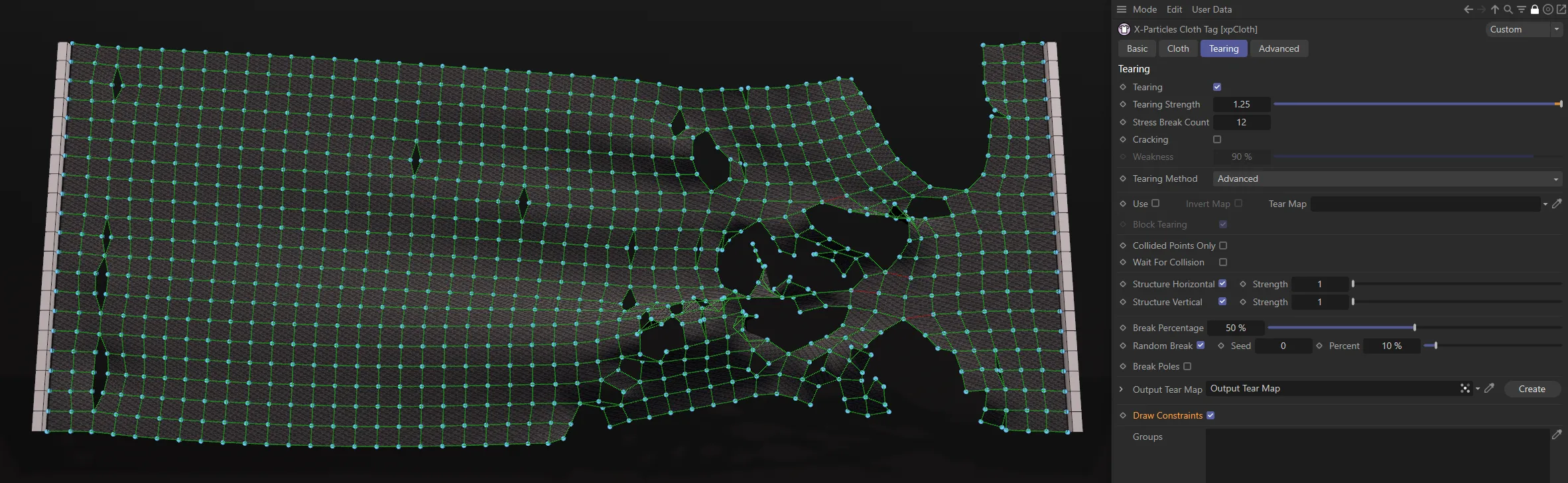
Draw Constraints is enabled in this image, with red lines visible where a break is about to occur.
Groups
Section titled “Groups”You can drag one or more particle groups into this list and only those groups will then tear.
In this animation, a Box field is controlling an xpChangeGroup modifier, changing particles from Particle Group 1 (blue circles) to Particle Group 2 (red filled circles). Group 2 has been set as the designated group in the xpCloth tag so, when particles are changed to this ‘viable’ group, the tearing effect is then instigated.
Advanced
Section titled “Advanced”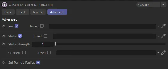
xpCloth Tag Advanced tab menu.
Pinning enables you to use a vertex map to indicate that some points should not be simulated at all.
It excludes them from the simulation and currently they are locked to world space coordinates.
The link field for a Vertex Map tag or Point Selection tag becomes available when this box is checked.
Invert
Section titled “Invert”If checked, this setting inverts the pin map so only those vertices in the map take part in the simulation.
Sticky
Section titled “Sticky”These options enable the sticking and peeling of cloth.
They will only work if the cloth is a polygon object.
Use a vertex map or point selection in the link field, to indicate which parts of the cloth are sticky.
This image shows a vertex map, painted for the Sticky effect used in the animations below.
The sticky sections of cloth will be static and will ignore any scene modifiers.
The non-sticky sections will be free to move.
The movement of the non-sticky sections of cloth will exert a force on the stuck sections.
When this force exceeds the Sticky Strength, the sticky cloth will begin to peel away.
The map, from the above image, is set in the Sticky link field, with Invert enabled, in this animation.
There is an inverted xpGravity modifier forcing the cloth upwards. The Sticky Strength is keyframed reduce over time.
Once the sticky strength reaches the value set, the cloth is able to peel away from its original position.
If you have Tearing active, you may need to increase the Tearing Strength, to ensure it doesn’t tear off before it is able to exert enough force to peel away the stuck cloth.
This animation is similar to the previous, except now Tearing is enabled, with an Edge Selection dropped in the Tear Map field.
Invert
Section titled “Invert”If checked, the sticky map is inverted.
Sticky Strength
Section titled “Sticky Strength”How strong the sticky constraint is.
Adjusting this, along with the vertex map, will define how sticky the surface is.
This scene is identical to the one above, but with the Sticky Strength value now raised to 1.122, resulting in pieces tearing before the cloth can be pulled up further.
Connect
Section titled “Connect”This option can be used when the cloth collides with another object, to pinpoint exactly where those connections are made.
It must be used in conjunction with a selection tag or a vertex map tag in order to initiate control over these connections.
The xpCollider tag has a Connect on Collision option to connect particles with the collider object when a collision occurs.
Connect on Collision is disabled in this first animation.
In this second scene, Connect on Collision is enabled.
This image shows the point selection for the connection map.
In this animation, the connections are only being made where the points were selected.
By direct comparison, a vertex map has been used here, with a completely different area painted. This is now the area where the connections are being made, in this final scene.
Invert
Section titled “Invert”If checked, the selection or vertex map is inverted.
Set Particle Radius
Section titled “Set Particle Radius”If checked, this option sets the size of the particles so that the xpConstraints object works for collisions with cloth and particles.
Normally this should be left checked.
Copyright © 2026 INSYDIUM LTD. All rights reserved.