xpBullet Soft Body
The xpBullet Soft Body tag gives a flexible, bendy dynamic to any object, when interacting with other objects in the scene.
Many of the settings are identical to xpBullet Rigid Body and illustrations for them can be found in that page.
xpBullet Rigid Body
Dynamics tab
Section titled “Dynamics tab”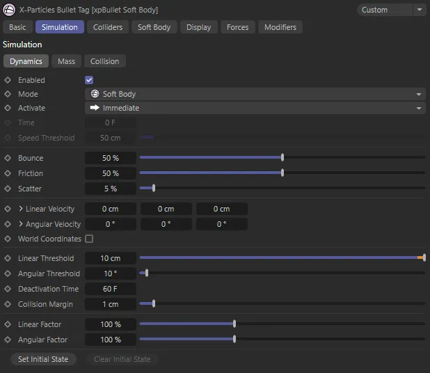
xpBullet Soft Body tag Dynamics tab menu settings.
Enabled
Section titled “Enabled”Checking this box enables the tag.
If this box is unchecked, the object to which the tag is attached will not be checked for collisions with any particles.
Set as Soft Body, by default, this changes the type of dynamic system being used.
The other options are: Collider and Rigid Body.
Activate
Section titled “Activate”Set as Immediate, by default, this setting determines when the dynamic system is activated.
The alternatives are: On Collision and After Time.
Sets the frame from when the dynamic system becomes active, when Activate is set to After Time.
Speed Threshold
Section titled “Speed Threshold”This setting is used when Activate is set to On Collision.
It dictates how fast a colliding object needs to be traveling, at the point of collision, for it to activate the object.
Bounce
Section titled “Bounce”Allows you to control the amount of bounce, on collision.
The bounce setting controls the speed with which the particle will rebound from the object.
A bounce of 100% means that the speed after hitting the object is the same as before hitting it.
Friction
Section titled “Friction”Gives control over friction forces, on collision.
Friction will cause the rolling particles to come to a halt.
The higher the setting, the more quickly they stop.
Scatter
Section titled “Scatter”This will allow you to introduce a degree of random reflection, upon impact.
When bouncing from flat surface, the particles will rebound at a reflected angle which is correct for the angle at which the particle strikes the surface.
For example, if the particle hits the surface at an angle of 90 degrees to it, the particle will bounce back in a direction which is the exact reverse of its original course.
This is geometrically correct but not necessarily realistic.
Scatter causes a degree or spread or scatter when the particle stream rebounds from a surface.
Linear Velocity
Section titled “Linear Velocity”You can use this parameter to give some initial velocity to the object along any of the desired axes, once animation begins.
Set as Relative, by default, this will allow you to set the Variation in percentages.
The alternative is Absolute, where you can set the Variation in centimetres.
Variation
Section titled “Variation”Can be set in each axis by either a percentage of variation (Relative setting) or in centimetres (Absolute setting).
Angular Velocity
Section titled “Angular Velocity”As with Linear Velocity, you can use this parameter to give some initial spin to the object around any of the desired axes.
Applies an initial velocity, by the degree set, giving a rotation, when the animation starts.
Set as Relative, by default, this will allow you to set the Variation in percentages.
The alternative is Absolute, where you can set the Variation in centimetres.
Variation
Section titled “Variation”Can be set in each axis by either a percentage of variation (Relative setting) or in centimetres (Absolute setting).
World Coordinates
Section titled “World Coordinates”By default, both linear and angular velocities are set using the object’s local axis.
Activating this setting uses the world axis coordinates.
Linear Threshold
Section titled “Linear Threshold”This setting is used, along with the Angular Threshold and Deactivation Time settings, to define when an object is considered to be in a ‘resting’ state.
If an object moves less than this amount, within the Deactivation Time, it will be considered resting.
Angular Threshold
Section titled “Angular Threshold”If an object rotates less than this amount, within the Deactivation Time, it will be considered resting.
Deactivation Time
Section titled “Deactivation Time”The time designated as after which an ‘active’ object is deemed as ‘resting’, dependent on the Linear Threshold and Angular Threshold values set.
Collision Margin
Section titled “Collision Margin”When a bullet object is in a ‘resting’ state, it will remain motionless until it becomes ‘active’ again.
It will become ‘active’ if another bullet object collides with it.
The Collision Margin adjusts the sensitivity of ‘resting objects’ to collisions.
Lower values will make it more likely to wake.
In most scenes, this setting can be left at the default value of 1cm.
Linear Factor
Section titled “Linear Factor”This setting acts a multiplier for the linear velocity of an object.
Angular Factor
Section titled “Angular Factor”This setting acts a multiplier for the angular velocity of an object
Set Initial State
Section titled “Set Initial State”Click this button to set the initial state of the object.
Clear Initial State
Section titled “Clear Initial State”Click this button to clear the initial state of the object.
Particle tab
Section titled “Particle tab”When the xpBullet Soft Body tag is placed on an xpEmitter, a Particle tab becomes available.
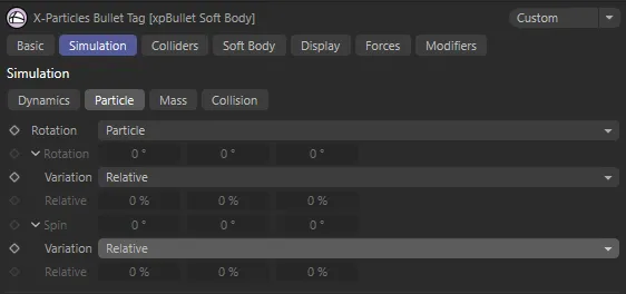
xpBullet Soft Body tag Particle tab menu settings.
Rotation
Section titled “Rotation”Set as Particle, by default, this controls the degree of Rotation on the axis set.
The other options are: Tangential and Custom.
Particle
Section titled “Particle”Particles will adhere to world settings from the xpEmitter during travel.
Tangential
Section titled “Tangential”Particles will now face the direction of travel.
Custom
Section titled “Custom”Allows you to set a custom degree of rotation on the different axes, using the Rotation parameters.
Variation
Section titled “Variation”Relative, by default, this sets a variation to the Rotation setting, in percentages.
The alternative is Absolute, which sets the variation in degrees.
Relative
Section titled “Relative”The variation relative to the Rotation set.
Adds degrees of spin to the different axes.
Variation
Section titled “Variation”Set as Relative, by default, this sets a variation to the Spin setting, in percentages.
The alternative is Absolute, which sets the variation in degrees.
Relative
Section titled “Relative”The variation relative to the Spin value set.
Mass tab
Section titled “Mass tab”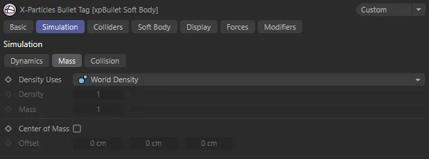
xpBullet Soft Body tag Mass tab menu settings.
Density Uses
Section titled “Density Uses”Set as World Density, by default,
The alternative settings are: Custom Density and Custom Mass (and Particle Mass, when your tag is on an xpEmitter).
World Density
Section titled “World Density”Gives all tagged objects the same density level.
Custom Density
Section titled “Custom Density”Using this setting allows you to give individual scene objects a customized density, by using the Density parameter.
Custom Mass
Section titled “Custom Mass”The volume of the objects has a bearing on the mass, unless you select Custom Mass, which allows you to give individual scene objects a customized mass, by using the Mass parameter.
Particle Mass
Section titled “Particle Mass”Allows you to change the particle mass inside the Extended Data tab of your xpEmitter, by using the Mass parameter within the Physical Data tab.
Density
Section titled “Density”When Density Uses is set to Custom Density, this parameter sets the density level for your object.
When Density Uses is set to Custom Mass*,* this parameter sets the mass level for your object.
Center of Mass
Section titled “Center of Mass”When unchecked, the tag will use a central point on your object as the center of mass, for all simulation purposes.
Checking this box will allow you to offset this center of mass by the amounts set in the different axes of the Offset parameter.
Offset
Section titled “Offset”When Center of Mass is checked, you can offset the object center of mass by values input in the different axes.
Collision tab
Section titled “Collision tab”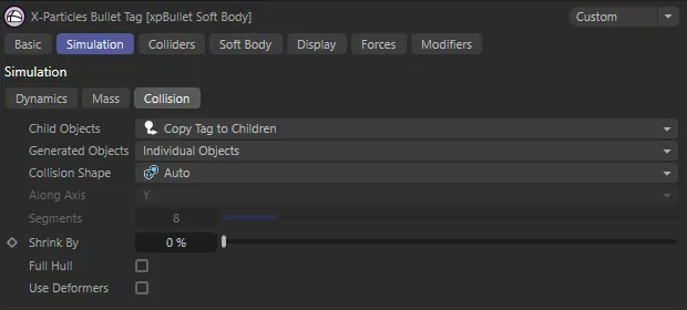
xpBullet Soft Body tag Collision tab menu settings.
Child Objects
Section titled “Child Objects”Set as Copy Tag to Children, by default, this sets the relationship the tag has with any children objects in the scene.
The other options are Ignore and Compound Object.
Copy Tag to Children
Section titled “Copy Tag to Children”All children of the object are also subject to the dynamics set in the tag.
Ignore
Section titled “Ignore”Any child objects will ignore the tag settings.
Compound Object
Section titled “Compound Object”The entirety of the object subject to the tag is seen as one, single object.
Generated Objects
Section titled “Generated Objects”Set as Individual Objects, by default,
The other options are: Compound Object, First Level and Second Level.
Collision Shape
Section titled “Collision Shape”Set as Auto, by default, with soft body simulations, the bullet system will intuitively select the Triangulated Mesh shape from the options available.
The other options are: Box, Sphere, Cylinder, Capsule, Convex Hull and Triangulated Mesh; you can manually select a different option for your collision shape should you prefer.
Along Axis
Section titled “Along Axis”This setting allows you to decide the orientation of the collision shape, on the X, Y or Z axis.
Segments
Section titled “Segments”Only available if the Collision Shape is set to Cylinder or Capsule, this setting allows you to increase or decrease the subdivisions on your collision shape.
Less segments will result in less calculations, therefore a faster simulation time.
More segments results in more calculations and a slower sim time but more accuracy when it comes to collisions between dynamic objects.
Shrink By
Section titled “Shrink By”Use this setting to reduce the size of the collision shape of the object.
Full Hull
Section titled “Full Hull”Only available when Collision Shape is set to Convex Hull or Auto (with certain shapes that necessitate the Convex Hull setting).
When enabled, this ensures that the collision shape is ‘wrapped’ around the collision object, whilst ensuring that the geometry is not intersected but also ignoring any indentations in the object.
Use Deformers
Section titled “Use Deformers”Checking this box will ensure that any deformers are taken into account, when the collision shape is generated.
Soft Body tab
Section titled “Soft Body tab”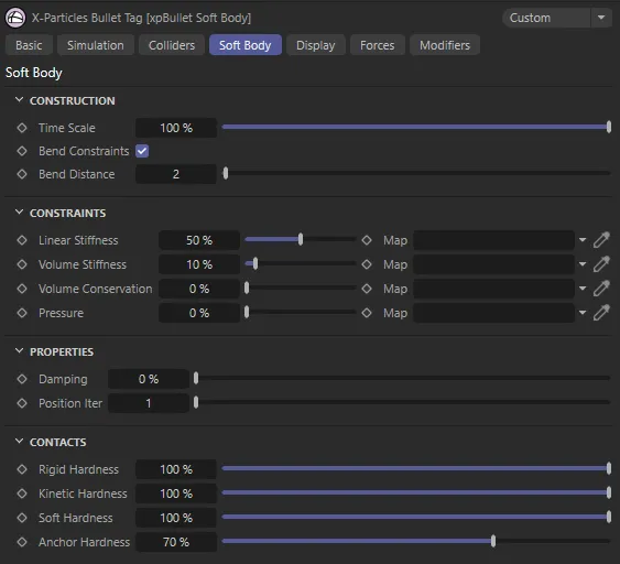
xpBullet Soft Body tag Soft Body tab menu settings.
Construction
Section titled “Construction”Time Scale
Section titled “Time Scale”This setting allows you to manipulate how xpBullet processes time.
Bend Constraints
Section titled “Bend Constraints”Checked by default, this setting activates bend constraints.
More bend constraints means a stiffer, more rigid soft-body simulation.
Bend Distance
Section titled “Bend Distance”Bend Distance is the search distance for bend constraints.
Set as 2, by default, increasing this value will enable a larger search for viable points to link with bend constraints.
This will result in a less bendy soft body dynamic object.
This animation demonstrates the effect of the Bend Distance parameter, with a value of 1, 2 and 3 set from left to right, respectively.
Constraints
Section titled “Constraints”Linear Stiffness, Map
Section titled “Linear Stiffness, Map”This setting alters the stiffness between the points of your mesh.
Vertex maps can be used to drive where the stiffer areas are.
In this scene, there is a contrast in the Linear Stiffness setting, from 0.5% (on the left), to 5% (in the middle) and finally 100% (on the right).
Volume Stiffness, Map
Section titled “Volume Stiffness, Map”By comparison, this setting alters the stiffness of the space inside your collision object.
Again, a vertex map can be dropped into the Map field, to give direction on where the volume is stiffest.
Volume Conservation, Map, Pressure, Map
Section titled “Volume Conservation, Map, Pressure, Map”The Volume Conservation parameter works in conjunction with the Pressure parameter to control the space inside your collision object, maintaining the shape.
The Volume Conservation setting works to keep the volume inside the shape the same, following any collision, preventing deflation.
The Pressure setting alters the pressure within the collision object.
As with the other constraints settings, vertex maps can be used to fine-tune where the conservation and pressure are targeted.
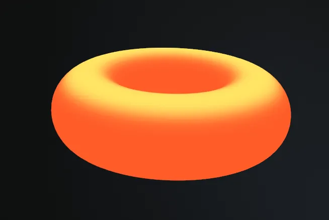
This is the vertex map, which is used in the animation, on the right.
With the vertex map dropped in the Map field and the Pressure value set high, at 3000%, positive pressure is created where there are bright areas in the vertex map, driving the Torus upwards towards the collider Cylinder.
Properties
Section titled “Properties”Damping
Section titled “Damping”This setting controls the damping factor, applied to the overall motion of the soft body.
Position Iter
Section titled “Position Iter”Increasing this parameter helps to retain the shape of your collision objects, giving more structural rigidity.
Contacts
Section titled “Contacts”The ‘hardness’ can be defined as the visual weight and energy that is transferred from one object to another during collision.
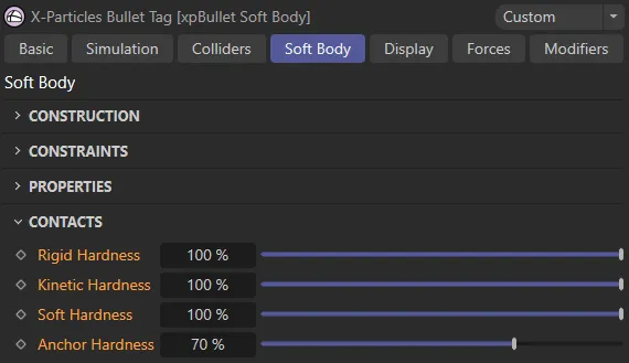
Within the Soft Body tab, here are the parameters available in the Contacts drop-down section.
Rigid Hardness
Section titled “Rigid Hardness”Controls the hardness levels of rigid bodies in your scene.
This scene contains a Sphere with an xpBullet Soft Body tag and a Cube with a Rigid Body tag. This first animation has Rigid Hardness on the Sphere set at 50% on contact with the Cube.
With Rigid Hardness on the Sphere raised to 9000%, the frenetic energy transferred to the Soft Body dynamic object on contact is increased.
Kinetic Hardness
Section titled “Kinetic Hardness”Controls the hardness levels of colliders in your scene.
By contrast to the above, these animations show the Kinetic Hardness on contact. In this animation it is only at 1%.
In this second scene, the Kinetic Hardness is raised to 1000%, causing greater damage to the soft body on collision.
Soft Hardness
Section titled “Soft Hardness”Controls the hardness levels of soft bodies in your scene.
Soft Hardness on the Sphere is set at 20%, on contact between the two objects, in this first scene. Note: The Soft Hardness on the Torus is set at 100% for both of these scenes.
With Soft Hardness increased to 850%, again there is greater damage to the soft body object (the Sphere).
Anchor Hardness
Section titled “Anchor Hardness”Sets the hardness of the anchor (can be displayed from a setting in the Display tab) between objects in your scene.
In these two animations, the xpBulletConstraints dynamic object is creating a fixed constraint between the collider (Cube) and the soft body (Sphere). As explained in the Display tab section below, the Anchor Connection can be seen in yellow, the Source in red and the Target in green. With a lower Anchor Hardness value, the constraint is relaxed in this first scene.
This second scene sees the Anchor Hardness value raised to 100%, which is keeping the anchor constraint stiff.
Display tab
Section titled “Display tab”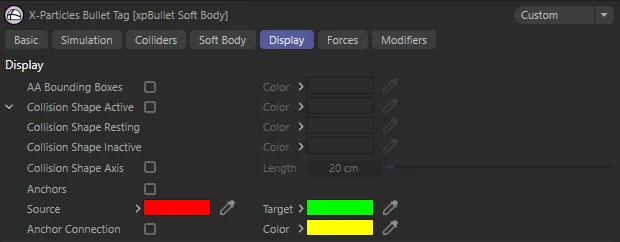
xpBullet Soft Body tag Display tab menu settings.
AA Bounding Boxes, Color
Section titled “AA Bounding Boxes, Color”When enabled, a bounding box (blue by default) will surround the object.
The collision engine uses adaptive bounds for the collisions.
Instead of testing every polygon in an object to see if a particle is colliding with it, the engine only tests relevant areas of the mesh.
It does this by dividing the mesh into smaller and smaller boxes until the area containing the correct polygon is found.
You can show the adaptive boxes as they are created by enabling this setting.
This can be useful if you have multiple colliders and you aren’t sure if particles are colliding with one of them.
The color can be changed in the Color setting.
Collision Shape Active, Color
Section titled “Collision Shape Active, Color”When the box is checked, the object will be surrounded by a wireframe (pink by default).
This wireframe is the collision shape that is used to control the collisions in the dynamic simulations.
This color can also be changed in the Color setting.
Collision Shape Resting, Color
Section titled “Collision Shape Resting, Color”This color is displayed as a wireframe surround when the object reaches a resting position.
Again, this color (green, by default) can be changed.
Collision Shape Inactive, Color
Section titled “Collision Shape Inactive, Color”When the object is inactive in the scene, the wireframe surround will be this color (yellow, by default).
This color can be changed using the Color setting.
Collision Shape Axis
Section titled “Collision Shape Axis”Enabling this setting will draw an axis from the tagged object’s center of mass.
The length of these axes can be extended in the Length parameter, below.
Length
Section titled “Length”Sets the length of the axis points.
Anchors
Section titled “Anchors”Enabling this setting, allows visualization of the anchors, the source and target points between the xpBullet constraints.
Source
Section titled “Source”Sets the color for the anchor source points.
Target
Section titled “Target”Sets the color for the anchor target points.
Anchor Connection, Color
Section titled “Anchor Connection, Color”Check this box to establish a visible anchor connection between objects in your scene (this must be set up in xpBulletConstraints).
The color can be changed in the Color palette.
Copyright © 2026 INSYDIUM LTD. All rights reserved.