xpBullet Rigid Body
The xpBullet Rigid Body tag gives a rigid dynamic to any object, when interacting with other objects in the scene.
Dynamics tab
Section titled “Dynamics tab”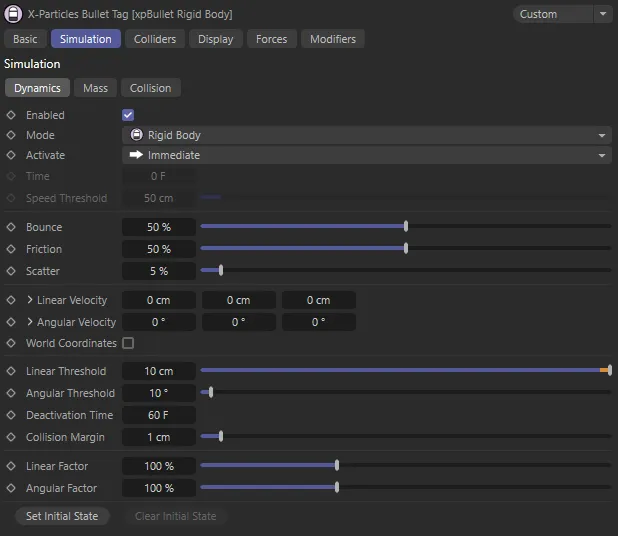
xpBullet Rigid Body tag Dynamics tab menu settings.
Enabled
Section titled “Enabled”Checking this box enables the tag.
If this box is unchecked, the object to which the tag is attached will not be checked for collisions with any particles.
Set as Rigid Body, by default, this changes the type of dynamic system being used.
The other options are: Collider and Soft Body.
Activate
Section titled “Activate”Set as Immediate, by default, this setting determines when the dynamic system is activated.
In this first animation, Activate is set as Immediate. activating the xpBullet world gravity straightaway.
The alternatives are: On Collision and After Time.
Here, Activate is changed to On Collision. As soon as the Sphere collides with the Cubes, the gravity is activated.
With Activate set to After Time, with a Time setting of 25 F, the bullet dynamic system activates on frame 25.
Sets the frame from when the dynamic system becomes active, when Activate is set to After Time.
Speed Threshold
Section titled “Speed Threshold”This setting is used when Activate is set to On Collision.
It dictates how fast a colliding object needs to be traveling, at the point of collision, for it to activate the object.
Bounce
Section titled “Bounce”Allows you to control the amount of bounce, on collision.
The bounce setting controls the speed with which the particle will rebound from the object.
A bounce of 100% means that the speed after hitting the object is the same as before hitting it.
In this animation, the Cube on the left has 5% Bounce, while the Cube on the right has 150% Bounce set.
Friction
Section titled “Friction”Gives control over friction forces, on collision.
Friction will cause the rolling particles to come to a halt.
The higher the setting, the more quickly they stop.
This scene illustrates the Friction settings, with 5% on the left-hand Sphere and 100% on the right.
Scatter
Section titled “Scatter”This will allow you to introduce a degree of random reflection, upon impact.
When bouncing from flat surface, the particles will rebound at a reflected angle which is correct for the angle at which the particle strikes the surface.
For example, if the particle hits the surface at an angle of 90 degrees to it, the particle will bounce back in a direction which is the exact reverse of its original course.
This is geometrically correct but not necessarily realistic.
Scatter causes a degree or spread or scatter when the particle stream rebounds from a surface.
The Cubes on the left have 0 (zero) % Scatter set, in this scene. On the right, there is a 35% Scatter value.
Linear & Angular Velocities
Section titled “Linear & Angular Velocities”Add initial linear and angular velocities to the dynamic object.
This animation demonstrates both the Linear Velocity and Angular Velocity. At the start, neither is set, so the cube just falls down due to the xpBullet world gravity. Next, 350cm of Linear Velocity is added on the Z axis and the Cube flies forwards at a rate of 350cm per second. Finally, 360 degrees of Angular Velocity is added on the banking rotational axis to rotate the Cube.
Linear Velocity
Section titled “Linear Velocity”You can use this parameter to give some initial velocity to the object along any of the desired axes, once animation begins.
Set as Relative, by default, this will allow you to set the Variation to the Linear Velocity in percentages.
The alternative is Absolute, where you can set the Variation to the Linear Velocity in centimetres.
Variation
Section titled “Variation”Can be set in each axis by either a percentage of variation (Relative setting) or in centimetres (Absolute setting).
Angular Velocity
Section titled “Angular Velocity”As with Linear Velocity, you can use this parameter to give some initial spin to the object around any of the desired axes.
Applies an initial velocity, by the degree set, giving a rotation, when the animation starts.
Set as Relative, by default, this will allow you to set the Variation to the Angular Velocity in percentages.
The alternative is Absolute, where you can set the Variation to the Angular Velocity in centimetres.
Variation
Section titled “Variation”Can be set in each axis by either a percentage of variation (Relative setting) or in centimetres (Absolute setting).
World Coordinates
Section titled “World Coordinates”By default, both linear and angular velocities are set using the object’s local axis.
Activating this setting uses the world axis coordinates.
Linear Threshold
Section titled “Linear Threshold”This setting is used, along with the Angular Threshold and Deactivation Time settings, to define when an object is considered to be in a ‘resting’ state.
If an object moves less than this amount, within the Deactivation Time, it will be considered resting.
Angular Threshold
Section titled “Angular Threshold”If an object rotates less than this amount, within the Deactivation Time, it will be considered resting.
Deactivation Time
Section titled “Deactivation Time”The time designated as after which an ‘active’ object is deemed as ‘resting’, dependent on the Linear Threshold and Angular Threshold values set.
Collision Margin
Section titled “Collision Margin”When a bullet object is in a ‘resting’ state, it will remain motionless until it becomes ‘active’ again.
It will become ‘active’ if another bullet object collides with it.
The Collision Margin adjusts the sensitivity of ‘resting objects’ to collisions.
Lower values will make it more likely to wake.
In most scenes, this setting can be left at the default value of 1cm.
Linear Factor
Section titled “Linear Factor”This setting acts a multiplier for the linear velocity of an object.
Angular Factor
Section titled “Angular Factor”This setting acts a multiplier for the angular velocity of an object
Set Initial State
Section titled “Set Initial State”Click this button to set the initial state of the object.
With Set Initial State clicked at 60 frames in, the initial state of the simulation is set so that the animation then begins from that state.
Clear Initial State
Section titled “Clear Initial State”Click this button to clear the initial state of the object.
Particle tab
Section titled “Particle tab”When the xpBullet Rigid Body tag is placed on an xpEmitter, a Particle tab becomes available.
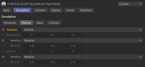
xpBullet Rigid Body tag Particle tab menu settings.
Rotation
Section titled “Rotation”Set as Particle, by default, this controls the degree of Rotation on the axis set.
The other options are: Tangential and Custom.
Particle
Section titled “Particle”Particles will adhere to world settings from the xpEmitter during travel.
Tangential
Section titled “Tangential”Particles will now face the direction of travel.
Custom
Section titled “Custom”Allows you to set a custom degree of rotation on the different axes, using the Rotation parameters.
In this animation, particles are traveling on a route determined by the xpSplineFlow modifier. They have Rotation set to Custom, with 360 degrees of Spin on all axes, which imparts continuous rotational spin throughout the animation. This can be negated by external forces, such as the particle to particle collisions seen in this example.
Variation
Section titled “Variation”Relative, by default, this sets a variation to the Rotation setting, in percentages.
The alternative is Absolute, which sets the variation in degrees.
Relative
Section titled “Relative”The variation relative to the Rotation set.
Adds degrees of spin to the different axes.
Variation
Section titled “Variation”Set as Relative, by default, this sets a variation to the Spin setting, in percentages.
The alternative is Absolute, which sets the variation in degrees.
Relative
Section titled “Relative”The variation relative to the Spin value set.
Mass tab
Section titled “Mass tab”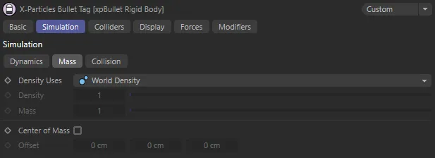
xpBullet Rigid Body tag Mass tab menu settings.
Density Uses
Section titled “Density Uses”Set as World Density, by default,
The alternative settings are: Custom Density and Custom Mass (and Particle Mass, when your tag is on an xpEmitter).
World Density
Section titled “World Density”Gives all tagged objects the same density level.
In this scene, the three sets of Cubes all have Density Uses set at World Density, which uses the object’s size to determine the density. As a result, the smaller objects are pushed much further than the larger objects, when hit with the same force. This gives the impression that the cubes are all made of the same material, thus having the same density, but differing in size.
Custom Density
Section titled “Custom Density”Using this setting allows you to give individual scene objects a customized density, by using the Density parameter.
When you use Custom Density mode, the volume of the object now has a bearing on its mass.
If all of the Density values are set the same, the larger objects will have a greater mass than the smaller ones.
In this second animation, the Density Uses are all set to Custom Density and now each set of Cubes is using completely different Density value settings When compared to the previous example, the smaller green Cubes are denser and harder to move and the largest orange Cubes are less dense and easier to move. The middle-sized blue Cubes behave in the same way as before because they have a Density value of 1, which is the world density.
Custom Mass
Section titled “Custom Mass”The volume of the objects has a bearing on the mass, unless you select Custom Mass, which allows you to give individual scene objects a customized mass, by using the Mass parameter.
With the Custom Mass mode, the size is now irrelevant.
With the same Custom Mass values, smaller object have the same weight as large objects.
The Density Uses are now all set to Custom Mass and, with an identical Mass value of 0.01 set, each group of Cubes is pushed the same distance.
Particle Mass
Section titled “Particle Mass”Allows you to change the particle mass inside the Extended Data tab of your xpEmitter, by using the Mass parameter within the Physical Data tab.
Density
Section titled “Density”When Density Uses is set to Custom Density, this parameter sets the density level for your object.
When Density Uses is set to Custom Mass*,* this parameter sets the mass level for your object.
Center of Mass
Section titled “Center of Mass”When unchecked, the tag will use a central point on your object as the center of mass, for all simulation purposes.
Checking this box will allow you to offset this center of mass by the amounts set in the different axes of the Offset parameter.
Offset
Section titled “Offset”When Center of Mass is checked, you can offset the object center of mass by values input in the different axes.
In this first animation, Center of Mass is checked, but with no Offset value, the center of mass is in the middle of the object. In the xpBullet tag’s Display tab, Center of Mass (visualized by the green circle) and Collision Shape Axis (which originates from the center of mass) have been enabled.
By comparison, with 60cm Offset in the Y axis, the center of mass is now higher, towards the tapered end, resulting in a top-heavy dynamic object.
Collision tab
Section titled “Collision tab”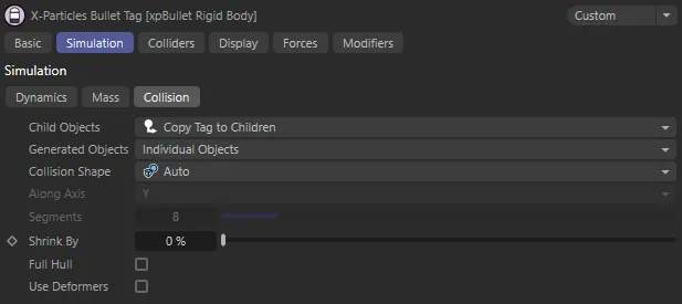
xpBullet Bullet Rigid Body tag Collision tab menu settings.
Child Objects
Section titled “Child Objects”Set as Copy Tag to Children, by default, this sets the relationship the tag has with any children objects in the scene.
The other options are Ignore and Compound Object.
Copy Tag to Children
Section titled “Copy Tag to Children”All children of the object are also subject to the dynamics set in the tag.
Ignore
Section titled “Ignore”Any child objects will ignore the tag settings.
Compound Object
Section titled “Compound Object”The entirety of the object subject to the tag is seen as one, single object.
Generated Objects
Section titled “Generated Objects”Set as Individual Objects, by default,
The other options are: Compound Object, First Level and Second Level.
Collision Shape
Section titled “Collision Shape”Set as Auto, by default, this setting allows you to select a collision shape for your collision object.
The other options are: Box, Sphere, Cylinder, Capsule, Convex Hull and Triangulated Mesh.
Box, Sphere, Cylinder and Capsule are efficient to calculate and some are customisable.
Convex Hull is efficient, though can lead to intersections; enabling Full Hull can mitigate this.
Triangulated Mesh is very accurate, at the expense of efficiency, and respects indentations etc.
Some of the Collision Shape settings need no further explanation but others are explained in more detail, below.
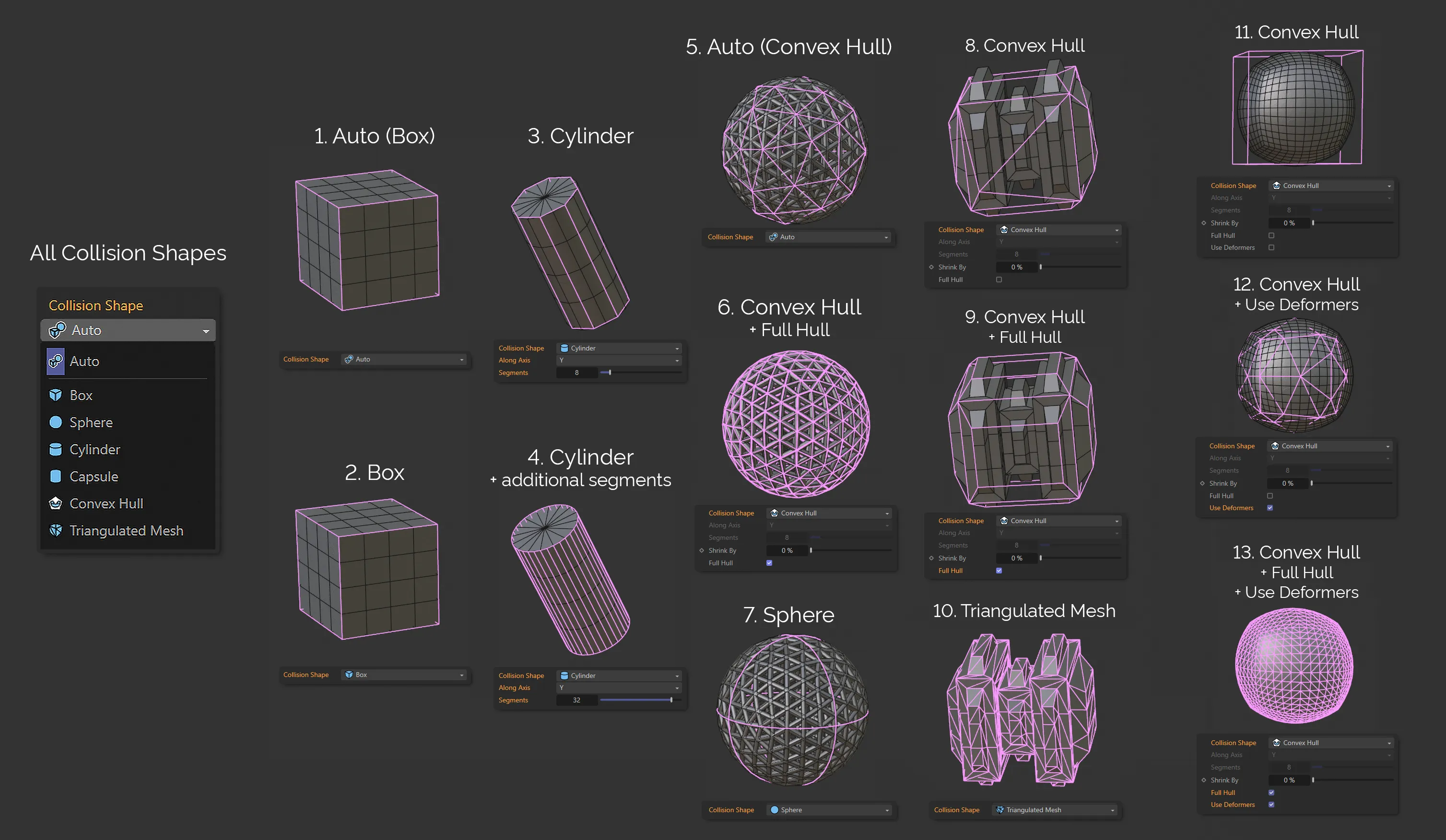
This image demonstrates Collision Shape choices, along with illustration mesh figures, which are referred to in the explanations below.
Selecting Auto, allows the bullet system to intuitively select a collision shape that it believes to be the best option.
If, for example, the dynamic object is a parametric Cube, the Collision Shape will automatically be set to Cube when Auto is selected (see image fig. 1 and 2.).
Some shapes are better suited for parametric objects (Box, Sphere, Cylinder and Capsule) but, when selected manually, rather than via Auto, some of these modes have settings that can be adjusted, such as Along Axis (for alignment) or Segment Count (see fig. 3 and 4.).
Convex Hull
Section titled “Convex Hull”When using Auto with a non-parametric dynamic object, Convex Hull is more likely to be chosen, where an efficient collision shape is generated around some of the outer-most points of the mesh (see fig. 5.).
This shape can result in intersecting meshes, however, as not all of the mesh is necessarily accounted for.
If you look at the top left of the Atom Array (fig. 5), the collision shape is made of few segments and, therefore, some of the base mesh is outside of the collision shape.
Enabling the Full Hull setting - explained below - will ensure that additional calculations are made when generating the collision shape, in order to account for any protruding parts of the mesh (see fig. 6.).
Importantly, sometimes stepping in and making a decision on the level of detail required can improve the simulation and reduce the calculation time.
For example, fig. 5 will result in an efficient collision shape, but rolling this shape down a hill would create a bumpy and uneven simulation due to the low-poly collision shape.
With Full Hull enabled in fig. 6., the resulting shape would roll down a hill nicely, but it may take a long time to calculate this collision shape, due to the amount of calculations required.
Stepping in and manually changing the Collision Shape to Sphere would create an efficient collision shape which calculates very quickly and would give a very smooth simulation when rolling down a hill.
Triangulated Mesh
Section titled “Triangulated Mesh”Unfortunately, the Convex Hull setting doesn’t respect holes, cavities, or indentations (a feature of the object in fig. 8 and 9, where the collision shape is drawn around the mesh, but never wraps internally).
Selecting the Triangulated Mesh mode (fig. 10.) enables the xpBullet system to create a collision shape to remedy this, albeit at the expense of additional calculation time.
Along Axis
Section titled “Along Axis”This setting allows you to decide the orientation of the collision shape, on the X, Y or Z axis.
Segments
Section titled “Segments”Allows you to increase or decrease the segment count of the collision shape.
Less segments will result in less calculations, therefore a faster simulation time.
More segments results in more calculations and a slower sim time but more accuracy when it comes to collisions between dynamic objects.
Shrink By
Section titled “Shrink By”Use this setting to reduce the size of the collision shape of the object.
Full Hull
Section titled “Full Hull”Only available when Collision Shape is set to Convex Hull or Auto (with certain shapes that necessitate the Convex Hull setting).
When enabled, this ensures that the collision shape is ‘wrapped’ around the collision object, whilst ensuring that the geometry is not intersected but also ignoring any indentations in the object.
Despite the Convex Hull setting being fast and efficient (as explained above), it can sometimes produce inaccurate and unusable collision shapes with unacceptable intersections (see fig. 8.).
Enabling Full Hull (fig. 9.) can solve this and (in comparison to fig. 6.) can sometimes still produce efficient collision shapes.
An additional example of the detail that can be added by the Full Hull setting can be seen in fig. 13.
Use Deformers
Section titled “Use Deformers”Checking this box will ensure that any deformers are taken into account, when the collision shape is generated.
In the image above, fig. 11. shows a Cube object, which has been deformed into a Sphere.
Without Use Deformers enabled, a simple box collision shape has been drawn.
Enabling Use Deformers (fig. 12.) generates a more appropriate Convex Hull setting, taking into account the deformers in use.
Display tab
Section titled “Display tab”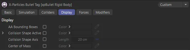
xpBullet Bullet Rigid Body tag Display tab menu settings.
AA Bounding Boxes, Color
Section titled “AA Bounding Boxes, Color”When enabled, a bounding box (blue by default) will surround the object.
The collision engine uses adaptive bounds for the collisions.
Instead of testing every polygon in an object to see if a particle is colliding with it, the engine only tests relevant areas of the mesh.
It does this by dividing the mesh into smaller and smaller boxes until the area containing the correct polygon is found.
You can show the adaptive boxes as they are created by enabling this setting.
This can be useful if you have multiple colliders and you aren’t sure if particles are colliding with one of them.
The color can be changed in the Color setting.
Collision Shape Active, Color
Section titled “Collision Shape Active, Color”When the box is checked, the object will be surrounded by a wireframe (pink by default).
This wireframe is the collision shape that is used to control the collisions in the dynamic simulations.
This color can also be changed in the Color setting.
Collision Shape Resting, Color
Section titled “Collision Shape Resting, Color”This color is displayed as a wireframe surround when the object reaches a resting position.
Again, this color (green, by default) can be changed.
Collision Shape Inactive, Color
Section titled “Collision Shape Inactive, Color”When the object is inactive in the scene, the wireframe surround will be this color (yellow, by default).
This color can be changed using the Color setting.
Collision Shape Axis
Section titled “Collision Shape Axis”Enabling this setting will draw an axis from the tagged object’s center of mass.
The length of these axes can be extended in the Length parameter, below.
Length
Section titled “Length”Sets the length of the axis points.
Center of Mass, Color
Section titled “Center of Mass, Color”Checking this box will reveal a small circle, which indicates where the center of mass is for the scene object tagged.
This color can be changed using the Color palette.
Copyright © 2026 INSYDIUM LTD. All rights reserved.