xpTrail
xpTrail will generate splines from the path of the particles during the animation.
The splines can then be used to generate other objects, such as in a Sweep object, or rendered with the X-Particles material.
General tab
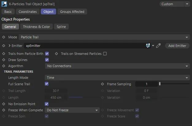
Section titled “General tab”Set as Particle Trail, by default the xpTrail object has two modes with different parameter settings.
The alternative is Object Trail.
Particle Trail
Section titled “Particle Trail”Creates particle trails from an X-Particles emitter.
This animation demonstrates the Mode setting of Particle Trail.
Object Trail
Section titled “Object Trail”Creates trails from an object in the scene.
With Cloner_Spheres dropped in the Object field, this animation shows the effect of the Mode being set as Object Trail.
Particle Trail mode parameters
Section titled “Particle Trail mode parameters”With Mode set as Particle Trail, the default interface is available.
xpTrail General tab Particle Trail mode menu.
Emitter
Section titled “Emitter”Drag an emitter object into this field for objects to be generated from particles.
Add Emitter
Section titled “Add Emitter”Click this button to create a new emitter and add it to the Emitter link field.
Trails from Particle Birth
Section titled “Trails from Particle Birth”If this is enabled, a trail will be generated for each particle as soon as it is created.
If it is unchecked, no trail will be generated for newly-created particles until this is checked again or until trail generation for a particle is turned on by an action.
Trails on Streamed Particles
Section titled “Trails on Streamed Particles”This is for use with the xpTendril modifier, which generates a lot of additional particles and usually you would not want them to have their own trails.
If this is disabled, no trails will be generated for particles created by the xpTendril modifier.
If enabled, each particle generated by the xpTendril modifier will have its own individual trail.
Draw Splines
Section titled “Draw Splines”If disabled, the xpTrail object will not generate splines, so they will not appear in the editor, or be rendered
They, therefore, cannot be used in an xpSplineMesher object or in a Sweep object.
Algorithm
Section titled “Algorithm”Set as No Connections, by default, this determines how trails can be used to connect particles or points in the generated trail.
The alternative options are: Straight Sequence, Segmented Sequence, Multiple Sequence, All Points to all Points, Nearest by Index, Nearest by Distance, Cluster, Tendrils, Constraints and Infectio.
Trail Parameters for No Connections setting
Section titled “Trail Parameters for No Connections setting”These are the basic particle trails.
Each particle has its own trail, which can be rendered or used in the xpSplineMesher or a Sweep object.
Length Mode
Section titled “Length Mode”Set as Time, by default, which is the time taken to draw the trail.
In this animation, the Length Mode is set as Time, with a Trail Length of 30 frames.
Length
Section titled “Length”The trail length can also be calculated in Length, the actual length in scene units.
This animation shows the alternate Length Mode of Length, with a Length setting of 300cm.
Full Scene Trail
Section titled “Full Scene Trail”Only used if Length Mode is set to Time.
If enabled, this will cause the Trail object to generate trails which are as long as the scene length.
If disabled, the trail length can be set with the Trail Length and Variation settings.
Frame Sampling
Section titled “Frame Sampling”Only used if Length Mode is set to Time.
By default, the spline will contain one point for each frame of the particle’s life.
You can reduce the number of samples by increasing the value here.
Trail Length
Section titled “Trail Length”Only used if Length Mode is set to Time.
The length of the trail, which will be produced, in frames.
A setting of 30, for example, will generate a trail over 30 frames of the particle’s life and will then cease to grow.
If you want trails to be generated for the entire life of every particle, enable the Full Scene Trail setting instead of using this parameter.
Variation
Section titled “Variation”Again, only available if Length Mode is set to Time.
This setting can be used to generate random variation in trail length.
The value in this field is combined with the Trail Length setting to produce trails of different lengths on each particle.
Length, Variation
Section titled “Length, Variation”The maximum length of the trail in scene units and the option to add variation to these lengths.
Only used if Length Mode is set to Length.
No Emission Point
Section titled “No Emission Point”By default, there is a small gap between the emission point and the start of the trail.
Disabling this setting will generate an extra point in the trail spline to remove this gap.
Freeze When Complete
Section titled “Freeze When Complete”Set as Do Not Freeze, by default, this controls what happens when the trail reaches its maximum length.
The other options are: Freeze Particle and Freeze Trail.
Do Not Freeze
Section titled “Do Not Freeze”When a trail reaches its maximum length, the particle keeps moving, dragging its trail behind it.
Freeze Particle
Section titled “Freeze Particle”If you want the particle to stop once the trail reaches the maximum length, select this option.
You can further opt to halt particle movement, spin and scale, independently.
In this animation, the Trail Length is set at 90 frames, with a Variation of 30 frames. With Freeze When Complete set at Freeze Particle, the particles are freezing when they reach their individual maximum lengths.
Freeze Trail
Section titled “Freeze Trail”With this option, the particle will not be frozen but the trail will be, so the trail and the particle will be disconnected.
With Freeze When Complete set at Freeze Trail, the particles disconnect when the trails freeze, as illustrated in this animation.
Freeze Movement/Spin/Scale
Section titled “Freeze Movement/Spin/Scale”You can use these settings to affect particle movement, spin and scale, independently.
Settings for Connection Algorithms
Section titled “Settings for Connection Algorithms”A variety of different algorithm modes are available for connecting particles together.
Straight Sequence mode
Section titled “Straight Sequence mode”Each particle is connected to the next one in the particle stream to form a single trail.
Animation demonstrating the Algorithm setting of Straight Sequence, creating a single trail of connected particles.
Connect Using
Section titled “Connect Using”Set as Particle Index, by default.
The other option is Particle Unique ID.
Particle Index
Section titled “Particle Index”The connection is between particles next to one another in the particle array.
Particle Unique ID
Section titled “Particle Unique ID”If you choose this option, the particles are connected using their own unique ID values.
These IDs are assigned in sequence, but never change.
If a particle in the middle of the particle array is deleted, the previous particle will simply connect to the particle with the next ID, minimising any change to the trail spline.
Skip Particles
Section titled “Skip Particles”This enables you to skip over the specified number of particles when connecting them together.
For example, if the value in this setting was 2, particle 1 would be connected to particle 4 (skipping 2 and 3), particle 4 to particle 7 (skipping 5 and 6) and so on.
This animation illustrates the effect of the Skip Particles parameter, in the Straight Sequence mode. Here, the value is 1, so particle 1 is connected to particle 3 (skipping 2), particle 3 to 5 and so on.
Set Max Length
Section titled “Set Max Length”The maximum length of the single trail can be set if this is enabled.
Length
Section titled “Length”The maximum length of the spline if Set Max Length is enabled.
Segmented Sequence mode
Section titled “Segmented Sequence mode”This is similar to Straight Sequence but enables you to divide the spline up into short segments with gaps between them.
This animation shows Algorithm changed to Segmented Sequence, with a Segment Length of 1 and a Gap Length of 1.
Segment Length
Section titled “Segment Length”The length of each segment.
The default value of 1 is the shortest possible segment, consisting of two adjacent particles linked together.
Gap Length
Section titled “Gap Length”The length of the gap between segments.
The default value of 1 is the shortest possible gap, which is the gap between two adjacent particles.
In this animation, with the same Algorithm setting, the Segment Length value is now 3, with a Gap Length of 3.
Multiple Sequence mode
Section titled “Multiple Sequence mode”This is similar to Straight Sequence but instead of a single long spline, you can emit multiple splines of varying length.
Set as Alternating, by default, this is to generate the splines from the particles.
The other option is Sequential.
Alternating
Section titled “Alternating”Each spline will be generated by taking a particle for each spline in turn then adding further points, again taking particles in turn.
For example, if Sequences is set to 2, splines will be created by joining particle 1 to particle 3, then to particle 5 and so on.
Then another spline will be created by joining particle 2 to particle 4, to particle 6, etc.
Animation to show the Algorithm setting of Multiple Sequence. The Mode is set as Alternating, with Sequences set as 2, as explained above.
Sequential
Section titled “Sequential”With this mode, the number of splines is controlled by the Length parameter, which is the number of points in each spline.
For example, if this is set to 10, a spline will be created using particles 1 to 10, then another spline using particles 11 to 20, etc.
In this animation, Algorithm is set to the same as above, but with the Mode set as Sequential and a Length value of 5.
Length
Section titled “Length”The length of the spline in terms of the number of particles used to create it.
Only used in Sequential mode.
Sequences
Section titled “Sequences”The number of sequences created by selecting particles in turn.
Only used in Alternating mode.
Again, this animation shows the Multiple Sequence setting, but the Mode is now Alternating, with a Sequences value of 3.
All Points to all Points mode
Section titled “All Points to all Points mode”In this mode, each particle is connected to every other particle to form a complex net.
There are no additional parameters for this mode.
This animation demonstrates the effect of the All Points to all Points Algorithm setting, with each particle attached to every other particle.
Nearest by Index, Nearest by Distance and Cluster modes
Section titled “Nearest by Index, Nearest by Distance and Cluster modes”These algorithms share the following two settings, giving the ability to specify which particle groups are used.
Destination Groups
Section titled “Destination Groups”Set as Use all Groups, by default, this lets you select which particle groups are used in making the connections.
The other options are: Only Same Group, Only Different Groups, Specific Group and All Except Specific Group.
Use all Groups
Section titled “Use all Groups”Each particle will form connections to other particles, regardless of which group they are in.
Only Same Group
Section titled “Only Same Group”Each particle will only form connections to particles in the same group as itself.
Only Different Groups
Section titled “Only Different Groups”Each particle will only form connections to particles in different groups to itself.
Specific Group
Section titled “Specific Group”Each particle will only form connections to particles in a specific group.
Specify which group to use by dragging the Group object into the Group link field.
All Except Specific Group
Section titled “All Except Specific Group”Each particle will only form connections to particles which are not in a specific group.
Specify which group to use by dragging the Group object into the Group link field.
The group to use in either of the two specific group options.
Nearest by Index mode
Section titled “Nearest by Index mode”In the Nearest by Index mode, each particle is connected to the nearest other particle(s) where proximity is measured, not by distance, but by the index in the particle stream.
Here, Algorithm is set to Nearest by Index, with a Max Connections value of 3.
The following two additional options are available with this setting.
Max Connections
Section titled “Max Connections”With the default settings, particle 1 would connect with particle 2, 2 to 3, 3 to 4 and so on, which is identical to Straight Sequence mode.
If Max Connections is set to 2, then particle 1 will connect to particles 2 and 3, 2 to 3 and 4, etc.
Skip Particles
Section titled “Skip Particles”If Skip Particles is set to higher than 0 (zero), not all particles will make connections.
If it is set to 1, particle 1 will connect to 2 and 3, particle 2 will be skipped and will not connect to any particles, particle 3 will connect to 4 and 5, particle 4 will be skipped, etc.
Nearest by Distance mode
Section titled “Nearest by Distance mode”In this mode particles are connected to each other depending on the distance between them in the 3D world.
The four additional options are available with this setting.
Distance Mode
Section titled “Distance Mode”Set as Nearest Only, by default.
The other options are: All Within Distance and Max Number Within Distance.
Nearest Only
Section titled “Nearest Only”Each particle will connect to its physically closest neighbor.
In this animation, Algorithm is set to Nearest by Distance, with the Distance Mode of Nearest Only and each particle connecting to its closest neighbor.
All Within Distance
Section titled “All Within Distance”Each particle will connect to every other particle which is closer to it than the value given in the Max Distance setting and no closer than the Min Distance setting.
Increasing the Max Distance value or decreasing the Min Distance value will result in more connections because more particles will be within that distance range.
Animation with the same settings as the one above, except the Distance Mode is now All Within Distance, with the distance being determined by the Max Distance parameter.
Max Number Within Distance
Section titled “Max Number Within Distance”The same as All Within Distance, except that you can use the Max Number setting to limit the maximum number of connections.
For example, if this is set to 5, and there are 10 particles within the threshold distance, connections will only be made to the 5 closest particles.
Max Distance, Min Distance
Section titled “Max Distance, Min Distance”If particles are closer together than Min Distance, or farther apart than Max Distance, they will not form a connection.
Max Number
Section titled “Max Number”This is the maximum number of connections a particle can make.
Cluster mode
Section titled “Cluster mode”In this mode particles are connected to each other in groups or clusters.
The following two additional options are available with this setting.
This animation shows the Algorithm setting of Cluster, with the additional settings of Cluster Distance (75) and Min Particles in Cluster (15).
Cluster Distance
Section titled “Cluster Distance”All particles in a cluster must be within this distance of one another.
Increasing this value will give larger clusters but fewer of them.
Min Particles in Cluster
Section titled “Min Particles in Cluster”The absolute minimum is 2, in which case the two particles are linked by a straight line.
As this value is increased, there must at least this many particles within the Cluster Distance of one another to form a cluster.
Tendrils mode
Section titled “Tendrils mode”This is a special mode for use with the xpTendril modifier.
It causes the xpTrail object to generate a single trail connecting all the particles in each tendril.
There are no additional parameters for this mode.
Constraints mode
Section titled “Constraints mode”If you are using constraints, collisions or particle to particle collisions, you can use this option to create a spline for each constraint or collision.
The spline can then be rendered with an X-Particles Material or the Cinema 4D Hair renderer, or used in an xpSplineMesher object or Sweep object.
It can also be utilized by third-party render engines such as Cycles 4D.
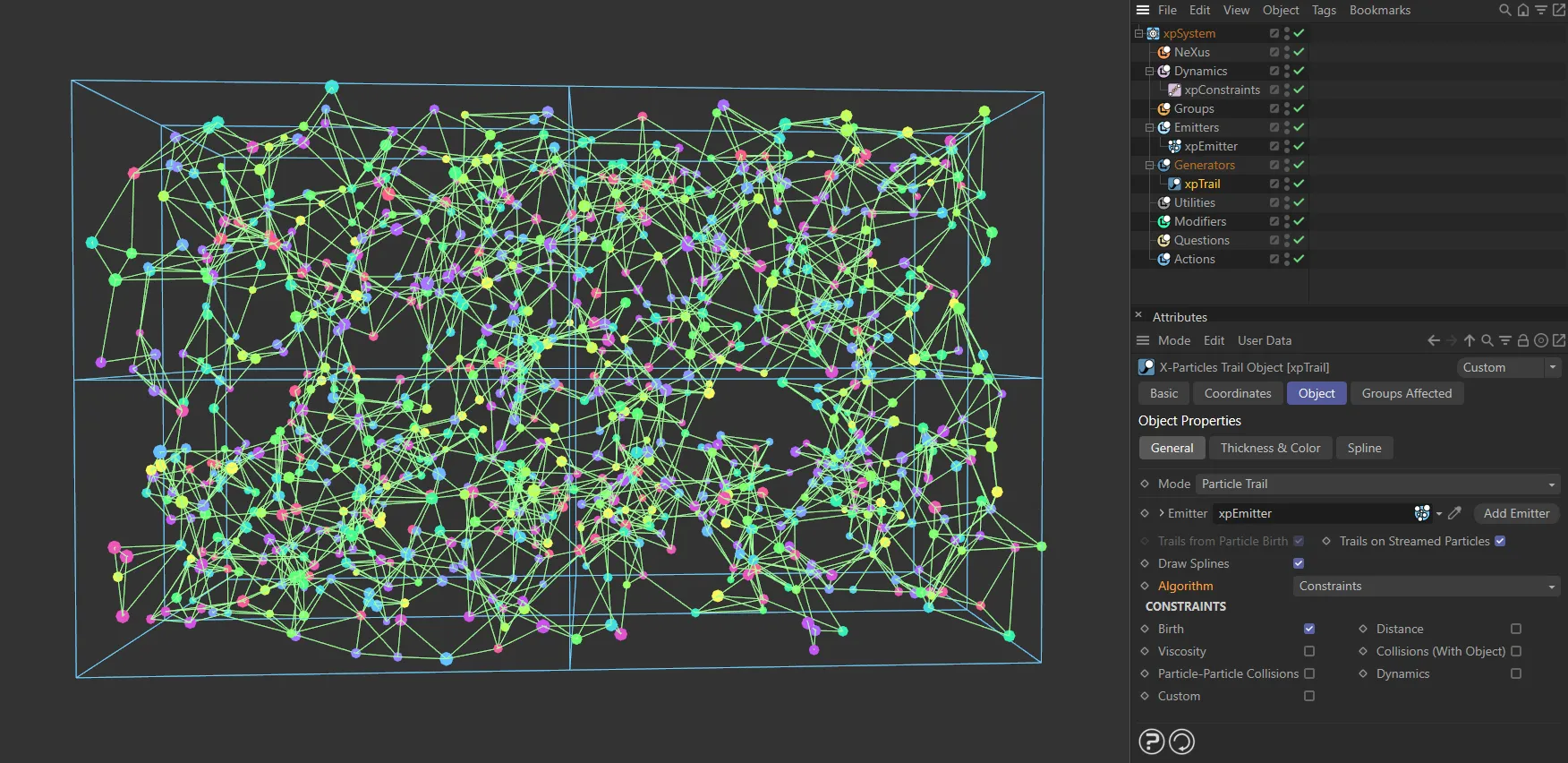
This image shows the Algorithm mode of Constraints, with Birth enabled, ensuring particles are linked from birth.
To create trails for these constraints, you must first turn on the required constraints in the xpConstraints object, then choose the constraints which will become splines in this section.
Simply enable the constraints to be included by the xpTrail object.
Collisions (With Object)
Section titled “Collisions (With Object)”To enable trails in this case requires a little more work.
You should first add an xpCollider tag to the relevant object.
Next, in the tag’s Connect section, turn on Connect on Collision.
Finally, in the xpTrail object, turn on Collisions (With Object).
When a particle collides with the object it will then connect to it.
Particle-Particle Collisions
Section titled “Particle-Particle Collisions”To generate trails when a particle to particle collision occurs, first add an xpPPCollisions (Particle-Particle) object to the scene.
Then, in that object, enable Connect on Collision and in the xpTrail object, turn on Particle-Particle Collisions.
Then a trail will be generated between particles when a collision occurs between them.
Infectio mode
Section titled “Infectio mode”This is a special mode for use with the xpInfectio modifier.
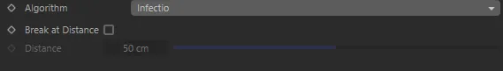
Infectio options.
The following two additional options are available with this setting.
Break at Distance
Section titled “Break at Distance”If this is enabled, trails will not be drawn between particles when the distance between them exceeds the value in the Distance setting.
Distance
Section titled “Distance”The maximum distance between two particles for a trail to be drawn.
Only available if Break at Distance is enabled.
Object Trail mode parameters
Section titled “Object Trail mode parameters”When you select the Object Trail option in Mode, the interface changes.
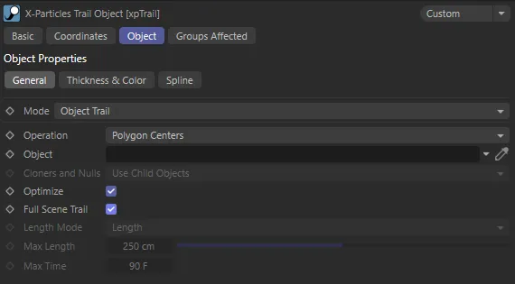
Object Trail mode parameter options.
With this option, you can create trails from an object rather than particles.
Operation
Section titled “Operation”Set as Polygon Centers, by default, this controls where the trails will commence from.
The alternative options are Vertices or Object Axis.
Vertices
Section titled “Vertices”Trails are created from the object’s vertices.
Polygon Centers
Section titled “Polygon Centers”Trails are created from the centre of each polygon in the object.
Object Axis
Section titled “Object Axis”A single trail is created from the object’s axis.
Object
Section titled “Object”Drag the object you want to use into this link field.
Cloners and Nulls
Section titled “Cloners and Nulls”Set as Use Child Objects, by default, this controls what happens if you add a MoGraph Cloner or a Null object to the link field.
It is only available if Operation is set to Object Axis.
The alternative setting is Use As Single Object.
Use Child Objects
Section titled “Use Child Objects”In this case, each child object of a Null object, or the clones produced by a Cloner, are used as the source for the trails.
The Null or Cloner object itself does not generate a trail.
Use As Single Object
Section titled “Use As Single Object”With this option, the clones or child objects are ignored and a single trail is generated from the position of the Cloner or Null object itself.
No other combination will work with a Null object with no child objects.
Optimize
Section titled “Optimize”Not available if Operation is set to Object Axis.
In the other modes, the xpTrail object will automatically collapse any object in the link field to produce one or more editable objects, then will join them all together to produce a single editable object.
This can sometimes lead to duplicated points and polygons.
If this is enabled, the collapsed mesh will be optimized before being used to generate trails.
Full Scene Trail
Section titled “Full Scene Trail”If this is enabled, the trail length will be that of the scene.
If it is disabled, there are additional options to set the desired length.
Length Mode
Section titled “Length Mode”Set as Length, by default, this determines how the length should be managed.
The alternative setting is Time.
This parameter is only available if Full Scene Trail is unchecked.
Length
Section titled “Length”Select this option to set a maximum length in scene units of the trail.
The length is specified in the Max Length parameter.
Select this option to set a maximum time for the trail generation.
One point per trail is added for each frame, so if this option is selected and Max Time is set to 30 frames, the trail will be 31 points long (the extra point is produced on the starting frame of the scene).
Max Length
Section titled “Max Length”The maximum length of the trail if Length Mode is set to Length.
Max Time
Section titled “Max Time”The maximum length of the trail if Length Mode is set to Time.
Thickness & Color tab
Section titled “Thickness & Color tab”These settings generate additional data to control the ‘thickness’ of a trail.
This data is used by the X-Particles material to alter the ‘thickness’ and/or color of the rendered spline.
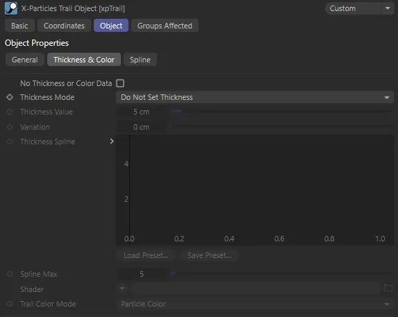
Thickness & Color tab settings.
No Thickness or Color Data
Section titled “No Thickness or Color Data”Enabling this prevents the xpTrail object from storing thickness or color data.
Thickness Mode
Section titled “Thickness Mode”Set as Do Not Set Thickness, by default, this drop-down controls how thickness is generated.
There are five other options, some of which are only available with certain Algorithm settings.
Do Not Set Thickness
Section titled “Do Not Set Thickness”No thickness data is created.
Set From Value
Section titled “Set From Value”With this option, the Thickness Value and Variation parameters become available and will set a uniform thickness along each trail.
Use Spline
Section titled “Use Spline”If this option is selected, the Thickness Spline and Spline Maximum parameters become available.
You can then set the thickness along the length of the trail with the spline control.
Use Shader
Section titled “Use Shader”If this option is selected, the Shader link field becomes available.
If you add a shader to this link, the shader is sampled for all points along the trail and that value is then multiplied with the value in Thickness Value to give the thickness along the length of each trail.
Use Radius (Current)
Section titled “Use Radius (Current)”With this option, the thickness depends on the current particle radius.
‘Current’ particle radius means the radius the particle has at any given frame.
This means that the thickness of the trail will be the same at all points and changing the particle radius (e.g. with an xpScale modifier) will alter the thickness of the whole trail.
Use Radius (Variable)
Section titled “Use Radius (Variable)”This is the same as Use Radius (Current) but instead of just using the particle’s current radius the radius is stored for each point in the trail.
This means that changing the particle radius will result in variable thickness along the spline.
Thickness Value, Variation
Section titled “Thickness Value, Variation”These fields are used to set the thickness in Set From Value mode and (for Thickness Value only) in the Use Shader mode.
Thickness Spline
Section titled “Thickness Spline”The spline control is used to set the thickness in Use Spline mode.
The thickness at the start of the trail is obtained from the value at the extreme left of the spline; the thickness at the end from the extreme right of the spline.
Spline Max
Section titled “Spline Max”The maximum possible value in the spline (by default, it is set to 100).
You can change the maximum value with this setting.
Shader
Section titled “Shader”Use this link field to choose a shader when in Use Shader mode.
A noise shader works well in this field and can be animated to give thickness which varies with time.
Trail Color Mode
Section titled “Trail Color Mode”Set as Particle Color, by default.
In addition to thickness, the trail color can be set for individual particle trails.
This drop-down menu controls how the color is used.
The other option is: Constraint Color.
Particle Color
Section titled “Particle Color”The entire trail has the same color, derived from the particle’s color.
If you change the particle’s color, its trail changes to that color along its length.
Per-Vertex Color
Section titled “Per-Vertex Color”A color is stored for each vertex in the trail spline.
If you change the particle color, that color is used for all new spline vertices, but existing ones are unchanged.
This enables you to have multi-colored trails for each particle.
Constraint Color
Section titled “Constraint Color”If the Algorithm menu is set to Constraints, the Per-Vertex option is removed and instead the option is Constraint Color.
Selecting this option will use the color given for the constraints in the emitter’s Display tab.
Spline tab
Section titled “Spline tab”The settings in this section are exactly the same as they are for all other splines in Cinema 4D.
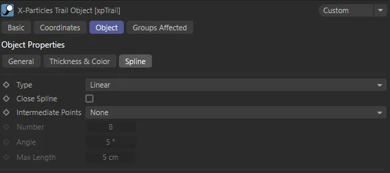
Spline tab options menu.
In other modes the spline will always appear to be linear (since the trail is then made up from multiple, independent, very short splines which cannot show curves).
Groups Affected tab
Section titled “Groups Affected tab”Groups
Section titled “Groups”To specify the group, drag and drop the desired Group object into this field.
This setting is useful if you want to ensure that the spawned particles are, or are not, affected by xpTrail.
Copyright © 2026 INSYDIUM LTD. All rights reserved.