xpSplineMesher
xpSplineMesher generates a mesh from xpTrails or spline objects.
It can also use the data generated by an xpBranch modifier to produce a single mesh from a multi-segment spline.
Object Properties
Section titled “Object Properties”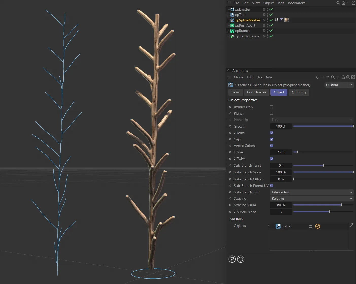
In this image, the spline on the left is being meshed into a renderable object, with xpSplineMesher.
Render Only
Section titled “Render Only”If this is enabled, meshing will only take place at render time, not during editing.
This can speed up the viewport significantly.
Planar
Section titled “Planar”Enabling this setting will make the mesh flat like a ribbon.
The direction of the mesh can be changed with the Plane Up parameter.
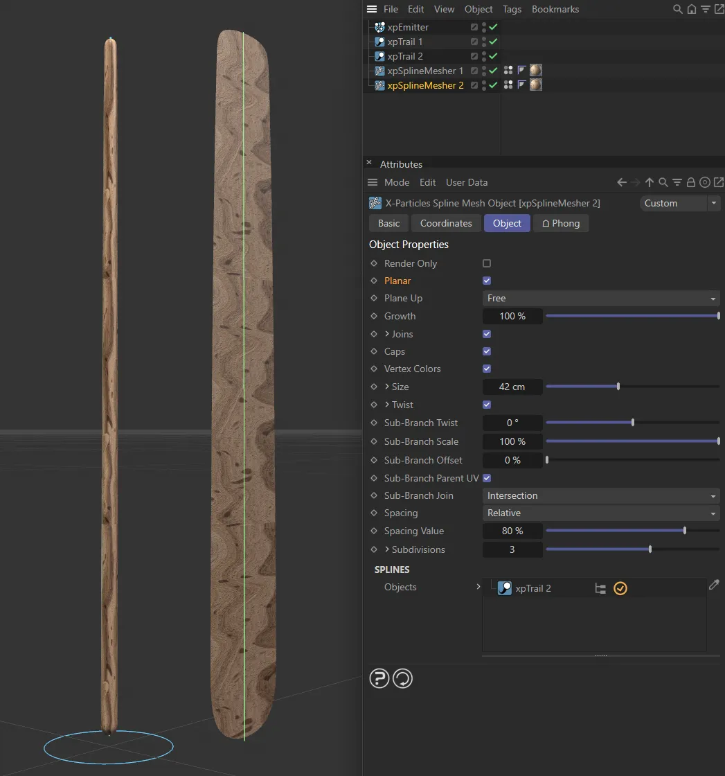
With Planar enabled, a 2D plane is being generated (rather than a 3D object).
Plane Up
Section titled “Plane Up”Set as Free, by default, this sets the direction of the mesh.
The alternative settings are: World X, World Y, World Z, Local X, Local Y and Local Z.
Growth
Section titled “Growth”This parameter affects what proportion of the spline will be meshed.
Set to 100%, the entire spline is meshed; anything less and only that part of the spline from the starting point will be meshed.
These settings control the joining of spline segments to make a single mesh.
Check the box to generate the joins.
The following three parameter settings are available by clicking the little arrow to the left of the word Joins.
Threshold
Section titled “Threshold”This is the minimum distance between spline segments for a join to take place.
If a segment is farther away than the threshold, no join will be produced.
Join at
Section titled “Join at”Set as Start, by default, this sets where the join will take place.
The alternative settings are: End and Start/End.
Parent
Section titled “Parent”If you think of a branching structure, each join has a parent segment (the one the branch is from) and a child segment (the branch itself).
Set as Order, by default, this setting controls how the parent is selected.
The other option is Longest.
Joins are generated between segments in order of the segments in the spline.
The parent is the segment with the lower index in the list of segments.
This is the option which works best with the X-Particles xpTrail object, when the Branching modifier has been used.
Longest
Section titled “Longest”The parent is the longer of the two segments.
Using this option with other multi-segment splines may result in a more natural appearance.
If this is enabled, the mesh will have end caps.
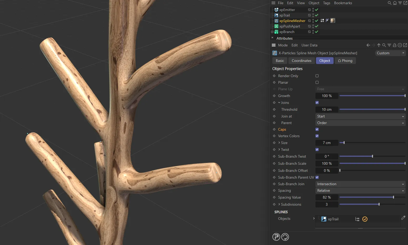
Caps are enabled in this first image.
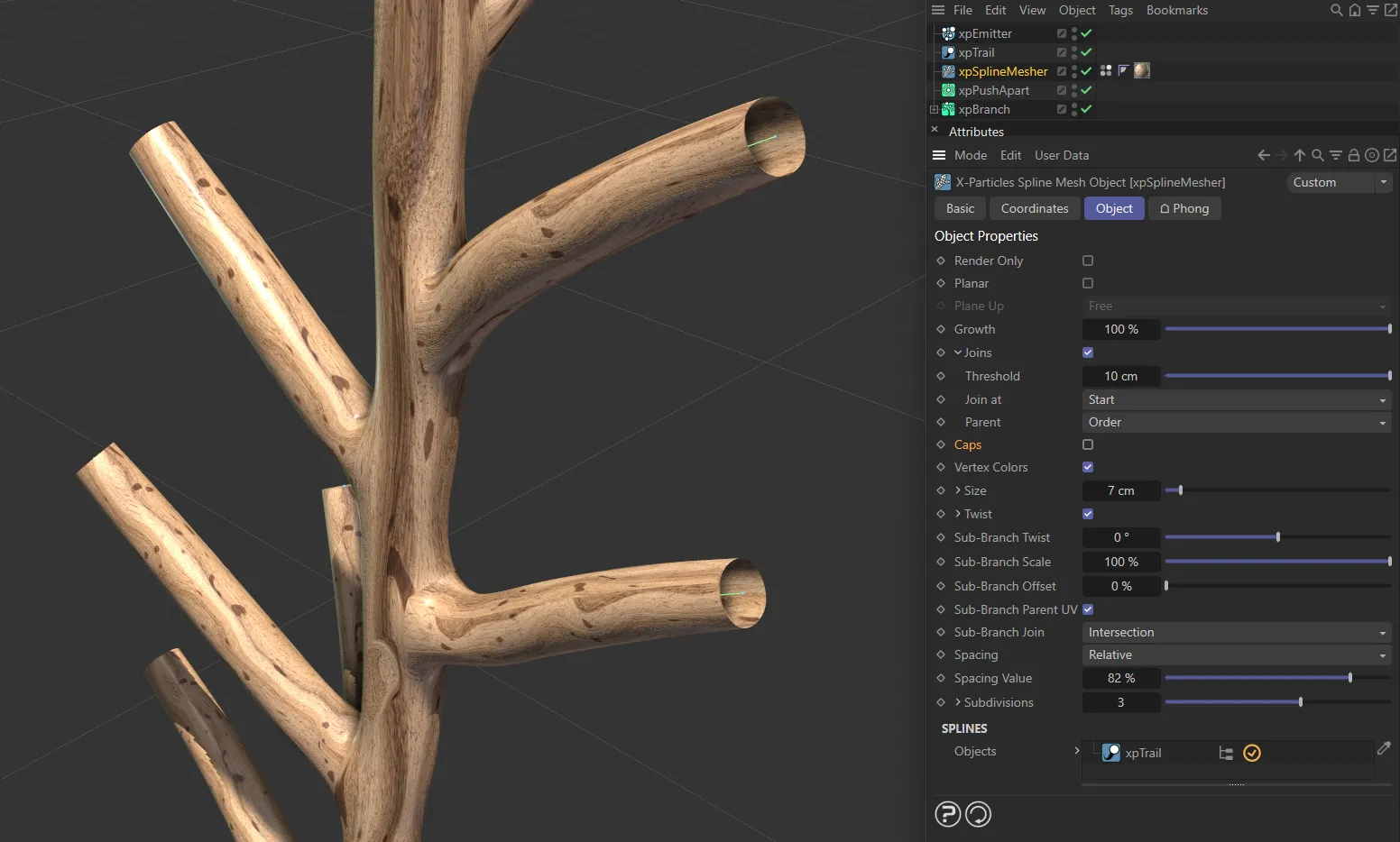
Caps are disabled in this second image.
This is the radius of the generated mesh.
Further control can be obtained by clicking the little arrow to the left of the word Size.
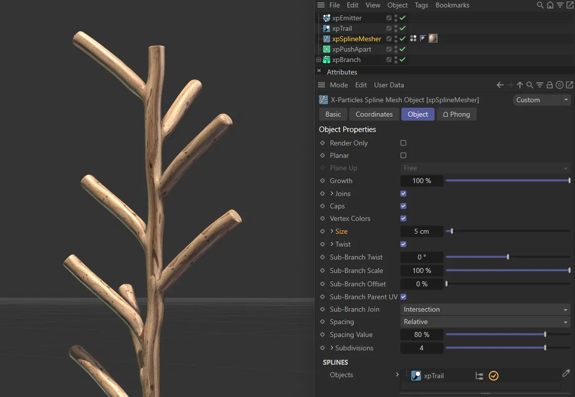
Size set at 5cm.
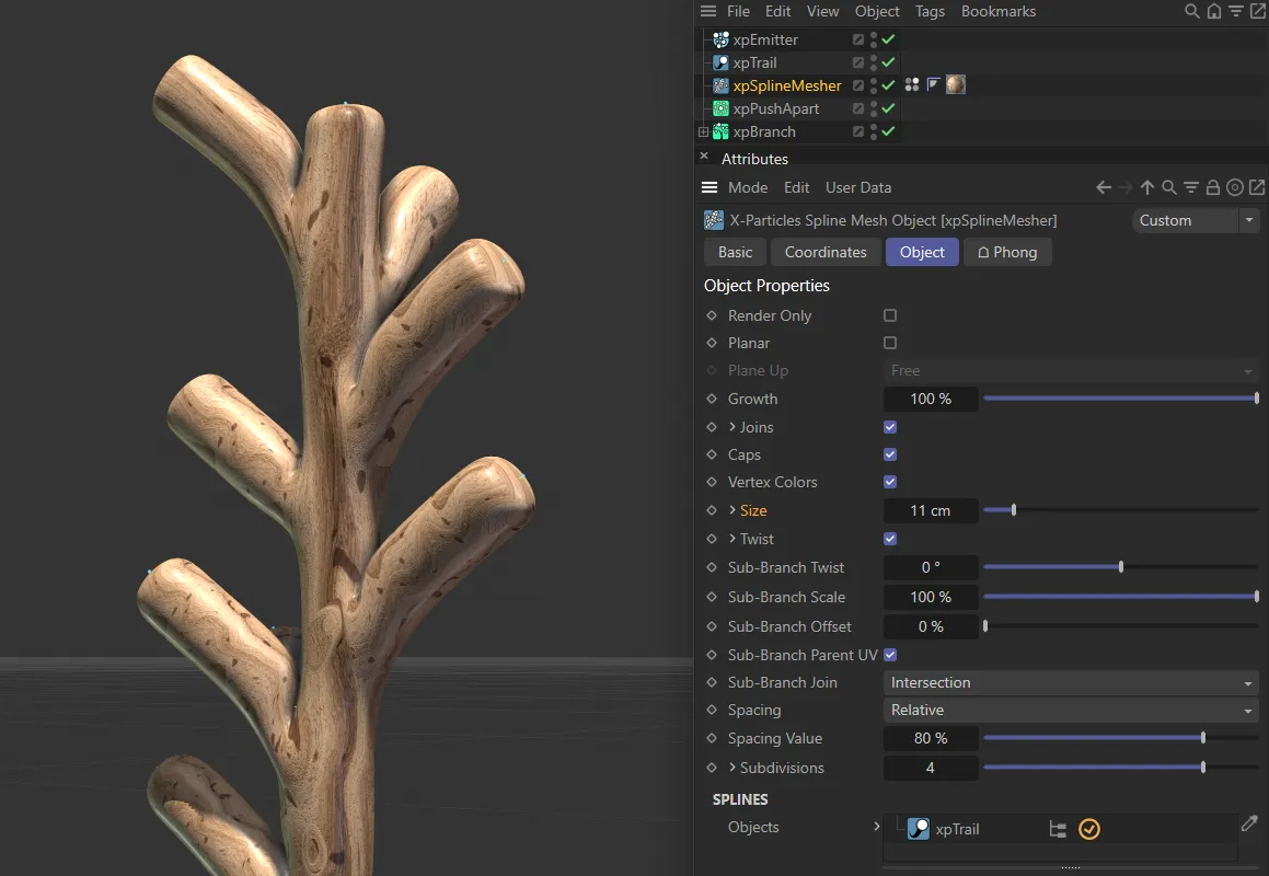
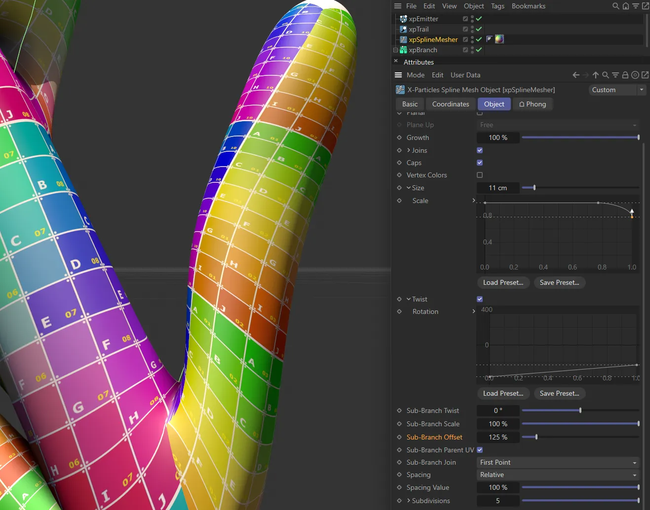
Size raised to 11cm.
This setting can be used to scale the mesh size.
This is a percentage scale; it can be used (for example) to taper the ends of the branch.
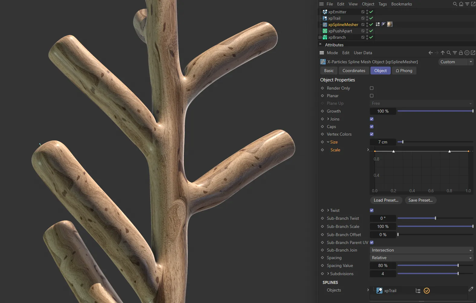
In this first image, the Scale is a linear spline, giving a constant scale throughout.
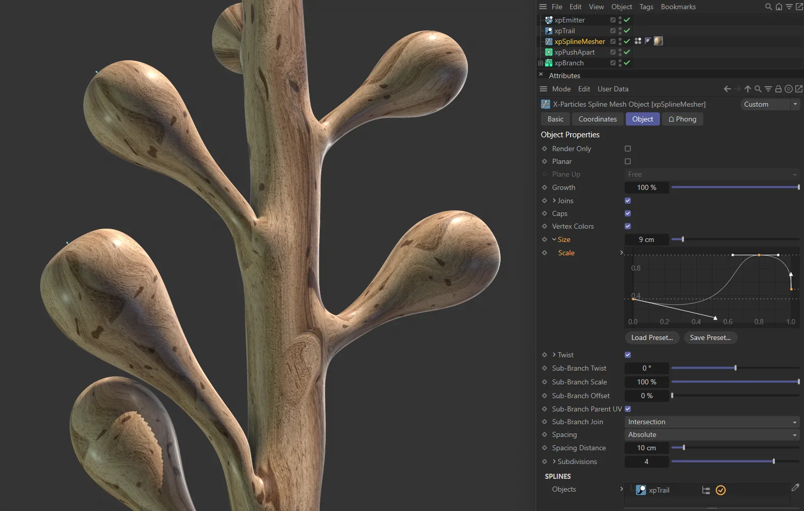
This custom Spline setting is driving the creation of bulbous tips.
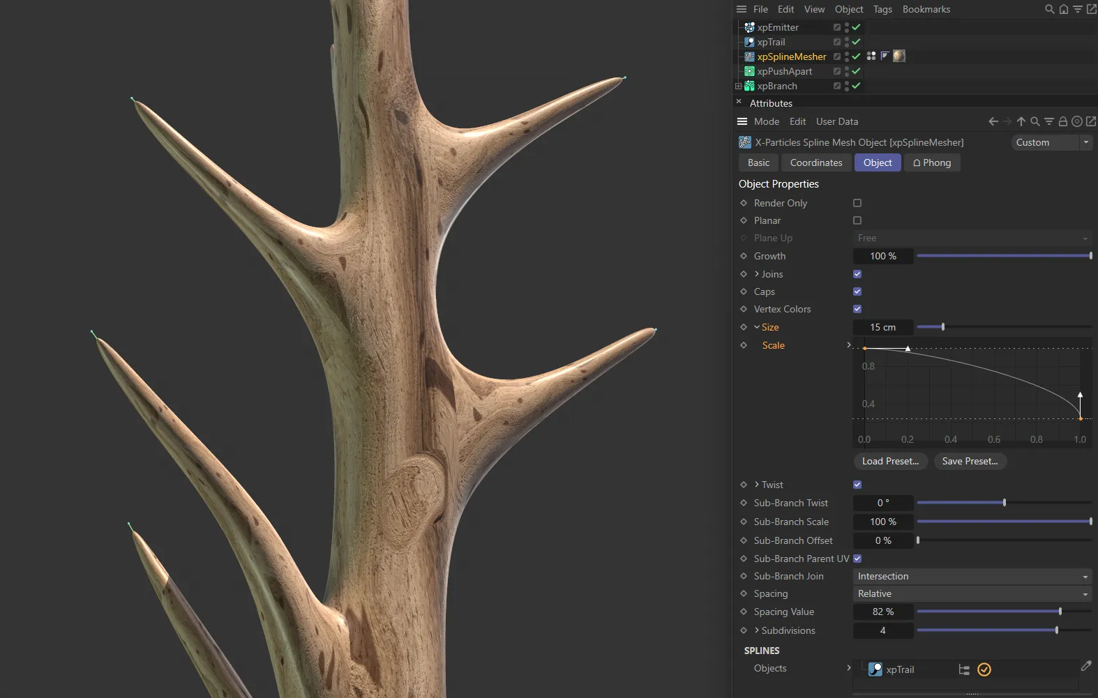
This final custom Spline setting tapers the tips off the end of the branches.
This option can be used to twist the entire mesh.
Each branch will be twisted along its length.
In order to set the amount of twist, first enable twisting by ticking this box, then click the little arrow to the left of the word Twist.
Rotation
Section titled “Rotation”This spline can be manipulated to set the rotation amount.
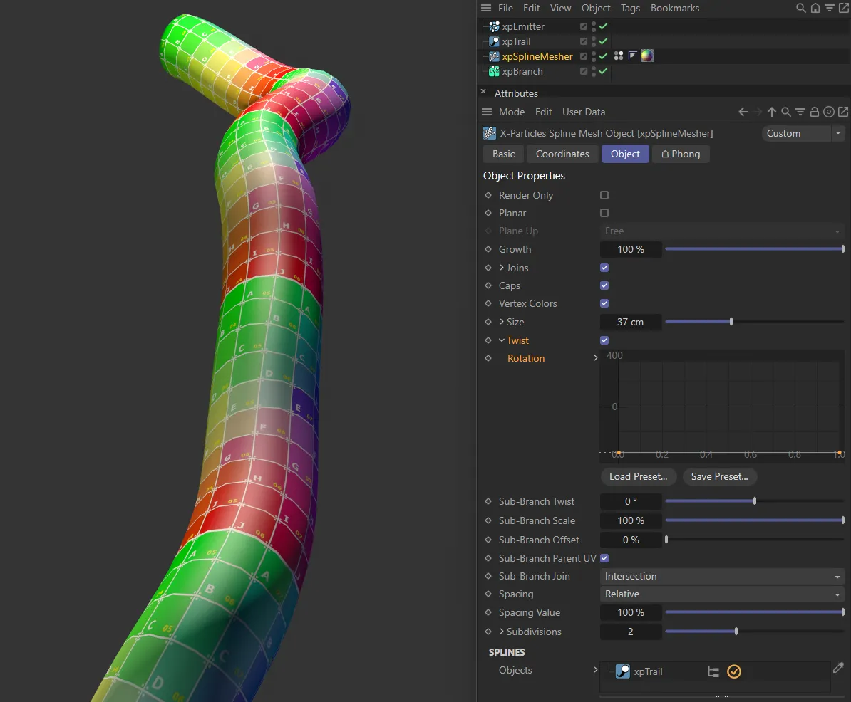
There is no Rotation set in this first image.
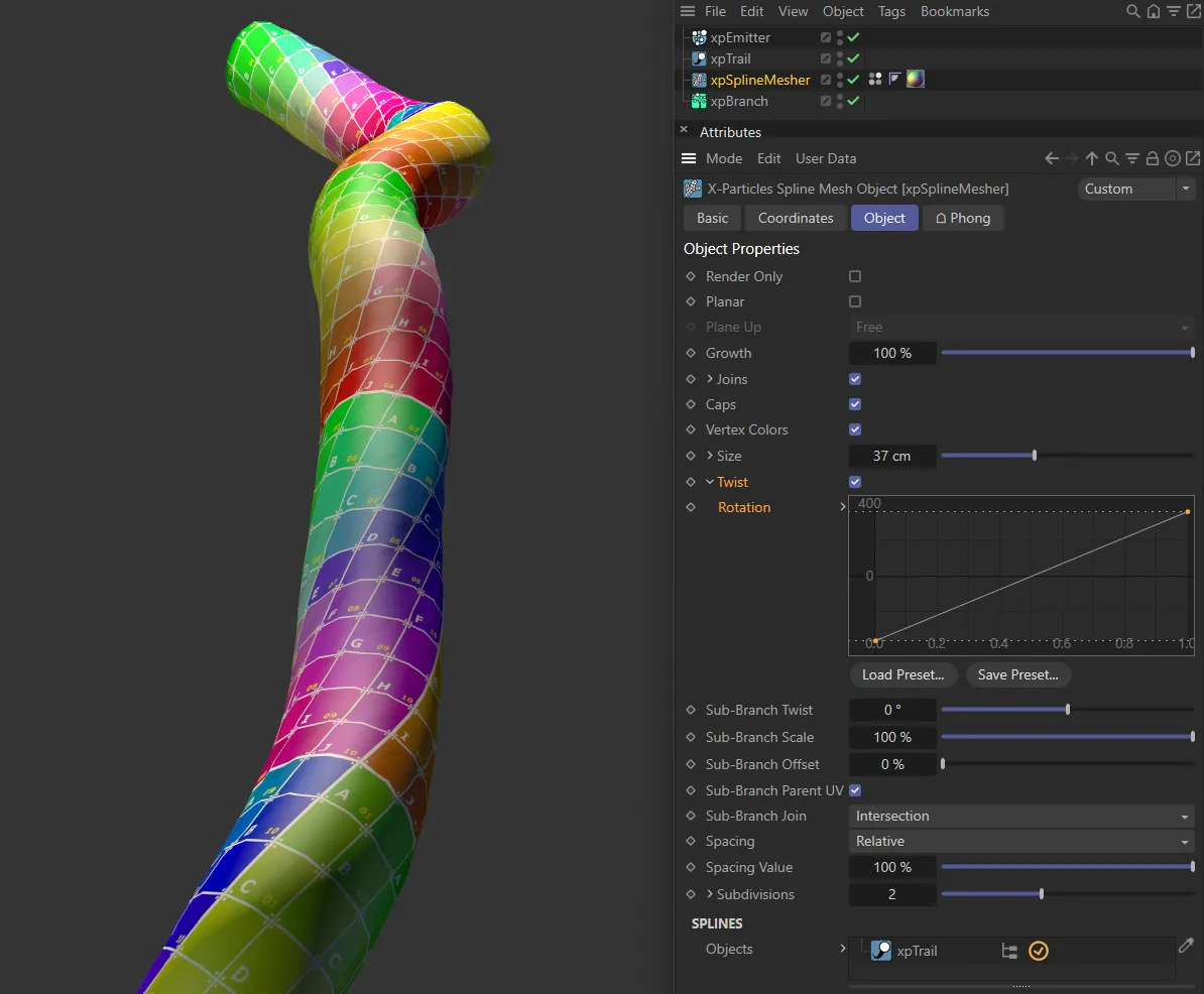
The rising linear Rotation spline is driving the rotation, here.
Sub-Branch Twist
Section titled “Sub-Branch Twist”This setting does not twist the branch itself, it rotates the entire branch around the join with its parent.
Unlike the twist setting, which affects all branches in the structure, only branches from another branch are affected.
Sub-Branch Twist set at 0 (zero) degrees.
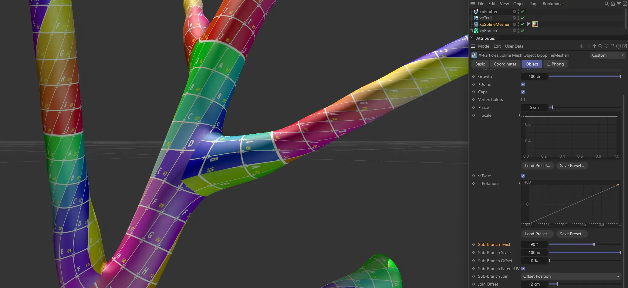
This branch is twisted around, with the Sub-Branch Twist set at 90 degrees.
Sub-Branch Scale
Section titled “Sub-Branch Scale”This control enables you to scale the radius of branches which are sub-branches from another branch.
The branch length is not altered.
It is a percentage scale, so if (for example) it is set to 50%, the initial ‘stem’ will be unchanged; any branches from the stem will be reduced in radius by half; any branches from those branches will be scaled down by half again and so on.
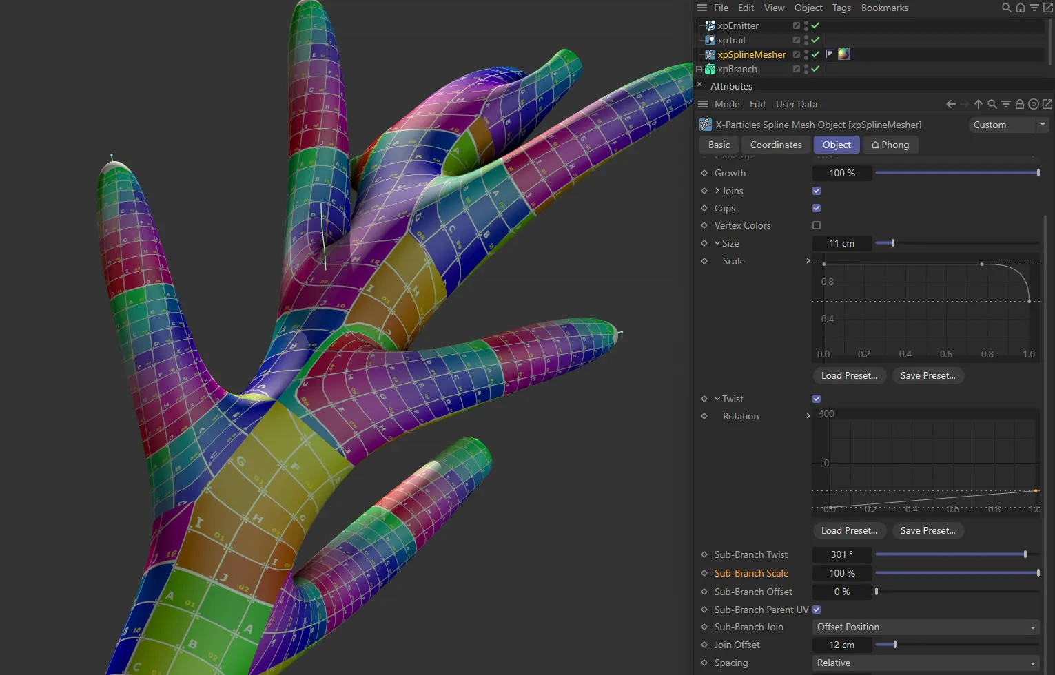
Sub-Branch Scale set at 100%.
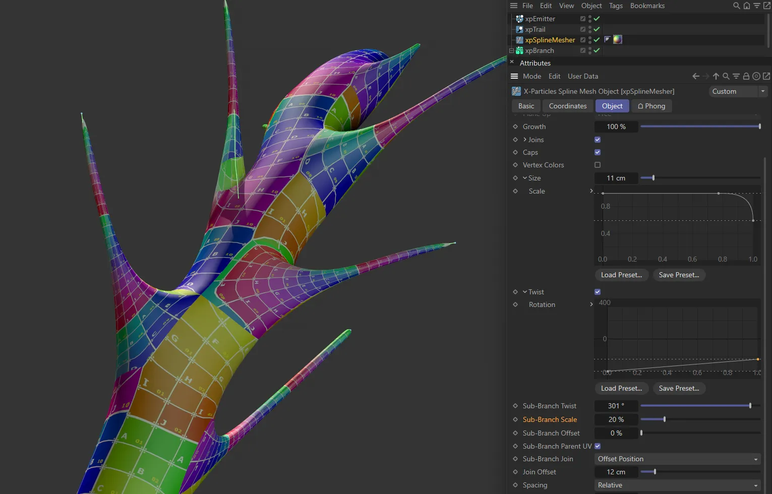
In this second image, the Sub-Branch Scale is decreased to 20%.
Sub-Branch Offset
Section titled “Sub-Branch Offset”This is an offset value for the start of the branch mesh from the join.
If this is too low, you may see artifacts in the mesh at the join point.
Increasing this value will relax the mesh and allow a better result.
Much of the time you will not need to alter this setting.
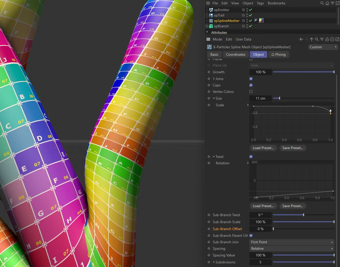
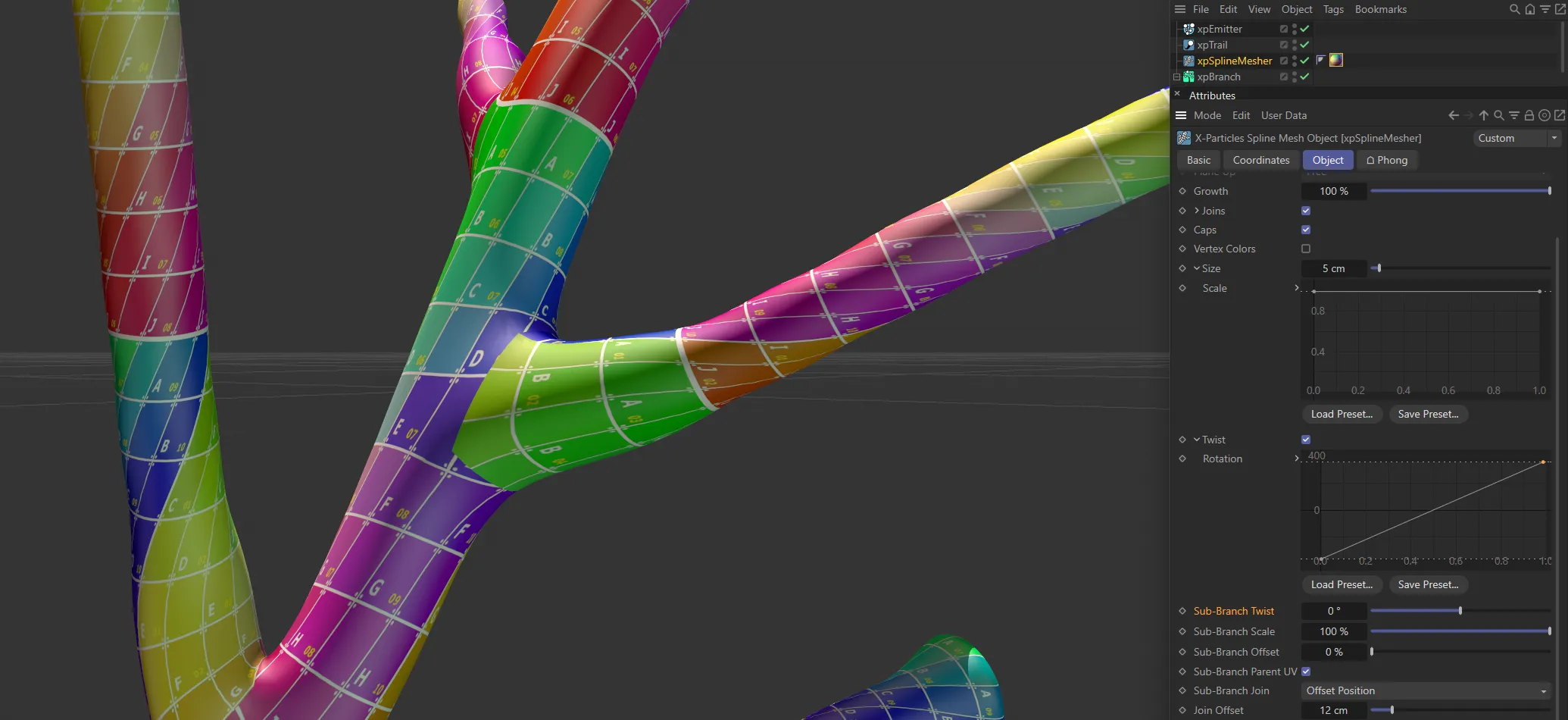
In this first image, the Sub-Branch Offset is set at 0 (zero) %.
With the Sub-Branch Offset increased to 125%, the mesh is relaxed around the base of the branch.
Sub-Branch Parent UV
Section titled “Sub-Branch Parent UV”When enabled, then where a sub-branch joins another (parent) branch it will generate the UVs starting with the UVs from the parent branch.
This is used to help textures continue along the parent branch down sub-branches.
Sub-Branch Join
Section titled “Sub-Branch Join”Set as Intersection, by default, this drop-down controls how a sub-branch is joined to the parent branch.
The other options are: First Point and Offset Position.
Intersection
Section titled “Intersection”The join takes place where the sub-branch spline intersects the parent branch geometry.
First Point
Section titled “First Point”The join occurs from the sub-branch’s first point.
Offset Position
Section titled “Offset Position”The sub-branch joins from the polygon that is closest to the offset position along the sub-branch.
The offset position is given in the Join Offset setting.
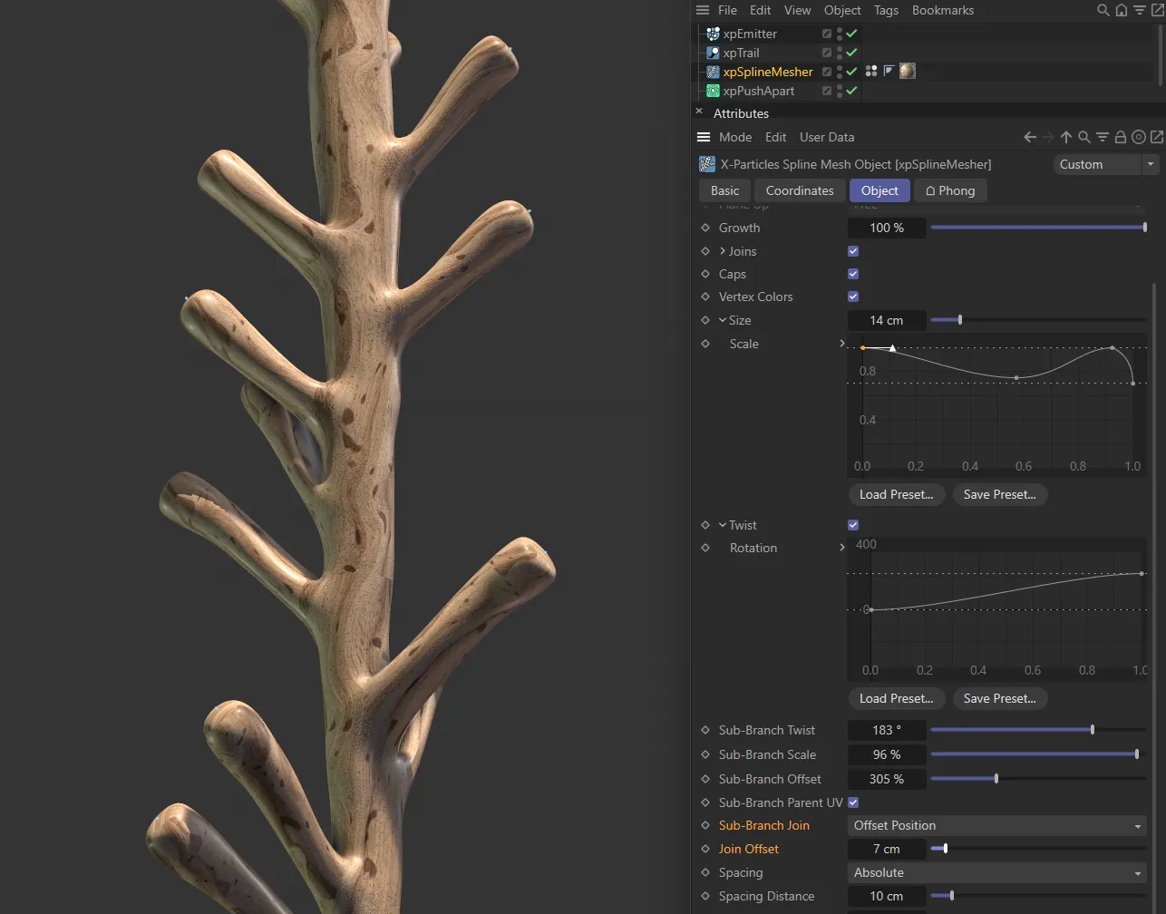
With Sub-Branch Join set to Offset Position, here the Join Offset is at 7cm.
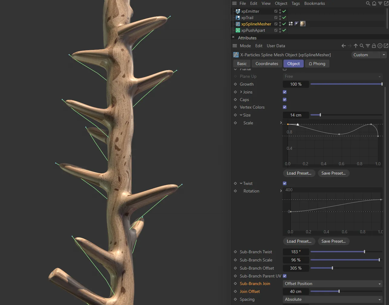
Here, the Join Offset is increased to 40cm, which makes the source spline visible.
Spacing
Section titled “Spacing”Set as Relative, by default, this governs the spacing of polygons in the generated mesh.
You can use it to generate denser or lighter meshes, depending on requirements.
Lighter meshes are more easily handled in the viewport but the shape may become distorted if there aren’t enough polygons to maintain it.
Denser meshes are smoother and tend to have better joins.
The alternative settings are: As Spline, Samples and Absolute.
As Spline
Section titled “As Spline”The mesher will use the spacing of vertices in the spline to control the polygon spacing.
This cannot be changed.
Samples
Section titled “Samples”This option enables a control parameter named Samples.
The polygon spacing is determined by taking a number of samples along the spline.
It differs from the Absolute and Relative options because short branches will be divided into the same number of polygons as large ones.
Increase the value in Samples for a denser mesh or decrease it for a lighter one.
Absolute
Section titled “Absolute”This option enables a control parameter named Spacing Distance.
This is a distance setting, controlling how far the polygons are apart.
As it is an absolute distance, shorter branches will have fewer polygons than long ones.
Increase this value for a lighter mesh or decrease it for a denser one.
Relative
Section titled “Relative”This option enables a control parameter named Spacing Value.
It works in the same way as Absolute, but using a percentage scale instead.
Samples
Section titled “Samples”The value to use if Spacing is set to Samples.
Spacing Distance
Section titled “Spacing Distance”The value to use if Spacing is set to Absolute.
Spacing Value
Section titled “Spacing Value”The value to use if Spacing is set to Relative.
Subdivisions
Section titled “Subdivisions”You can drop the mesher into an SDS object, if you wish, but the Subdivisions control will do the same thing.
Increase it to give a rounded, rather than a square, mesh.
A setting of 2 is the same as the SDS object, with its default settings.
Render Subdivisions
Section titled “Render Subdivisions”Click the small arrow next to the Subdivisions label to see this parameter.
This will alter the subdivisions of the spline mesher but will not change the subdivisions in the editor, only on rendering.
Splines
Section titled “Splines”Objects
Section titled “Objects”Drop the splines you want to mesh into this list box.
Copyright © 2026 INSYDIUM LTD. All rights reserved.