xpShatter
The xpShatter object is used to break polygon objects into shards using several different algorithms.
The shards can be controlled using X-Particles modifiers and dynamic objects.
This object is built around the concept of source layers each with its own hierarchy.
The xpShatter object must have at least one ‘Source Layer’ which is the source of the shattering and which, by default, is a conventional Voronoi shatter layer.
You can, however, add multiple layers, each with its own distinct hierarchy of settings and options and modify and/or delete the default layer if required.
If you have more than one shatter layer, the first layer will break the object, then the second layer will break the fragments of the object, and so on until all layers have been processed.
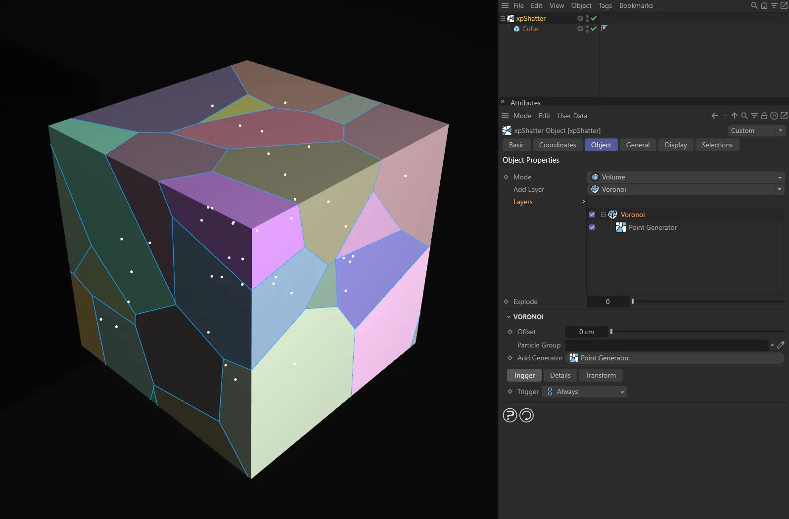
User Interface (UI) settings for the Voronoi layer.
Each source layer must in turn have at least one ‘Point Generator’, which actually generates the fragments of the object.
Again, you can have more than one point generator for each source layer if desired, each with its own settings.
The point generators must be child objects of the source layer.
Each point generator then has its own set of properties, some of which require additional objects such as a texture tag, a special xpPointContainer object, or another mesh object.
Finally, each point generator can also have optional ‘Point Modifier’ layers applied to it, such as Translate or Scale.
Make the object to be shattered a child of the xpShatter object and it will be broken using a single Voronoi source layer and a single Point Generator.
Then, you can add or remove source layers, add point generators, alter the settings etc. until you have the effect you want.
xpShatter Object tab menu.
Set as Volume, by default
The alternative is Surface.
Volume
Section titled “Volume”The shattering is carried through the volume of the object as though it was a solid object, so produces ‘solid’ fragments.
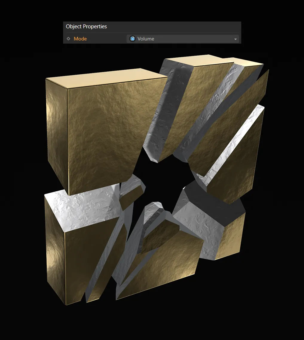
With the Mode set as Volume, with a silver material applied to the xpShatter’s inner faces.
Surface
Section titled “Surface”Only the surface of the mesh is broken, so produces thin, not solid, fragments.
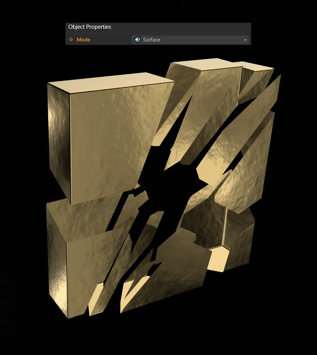
Here, the Mode is set as Surface. The silver material has now disappeared as there are no inner faces in Surface mode.
Add Layer
Section titled “Add Layer”The default setting is Voronoi, select the desired layer type from this menu to add a new source layer.
The other options are: Wood, Glass and Bricks.
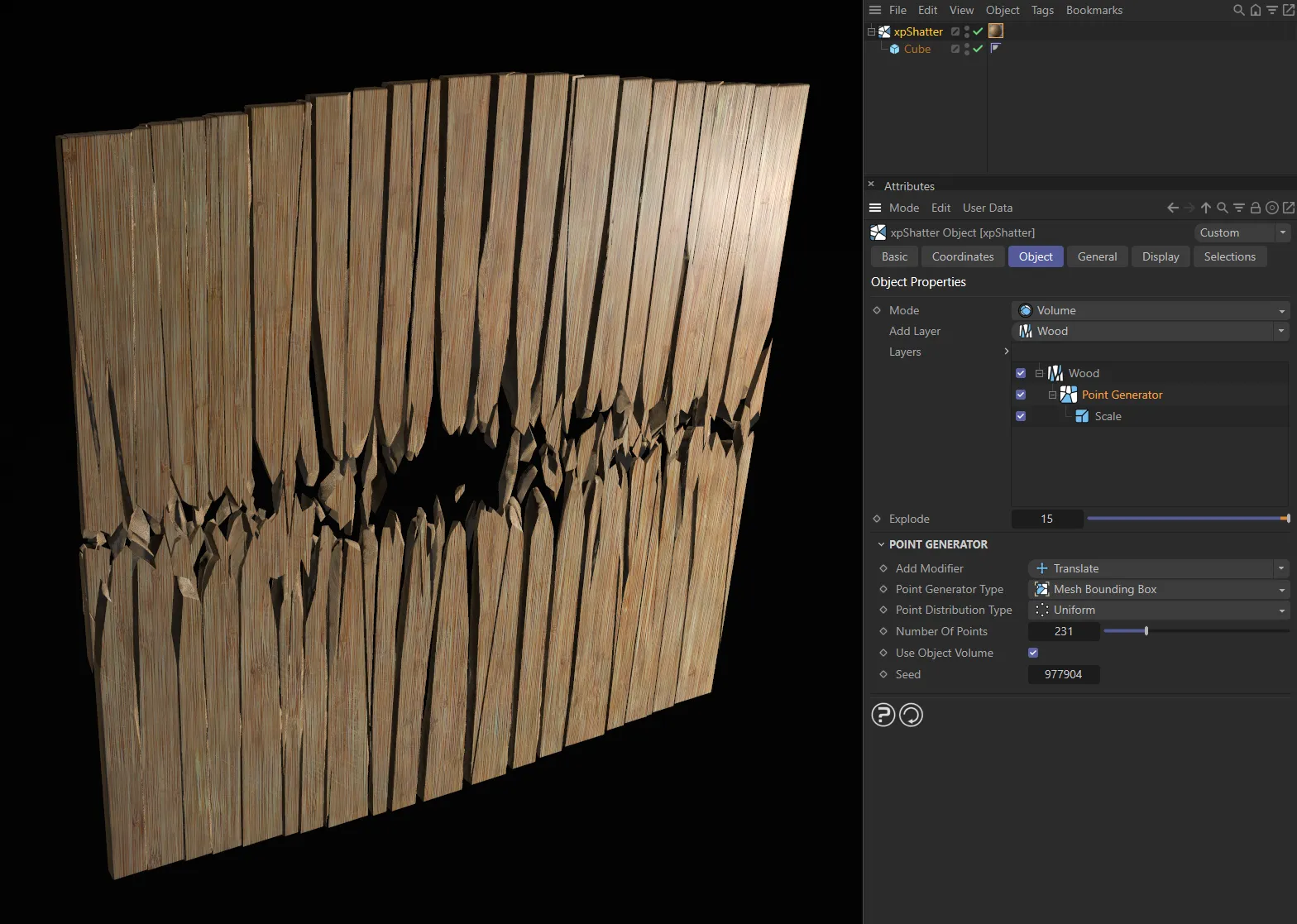
The Layer settings of Wood,
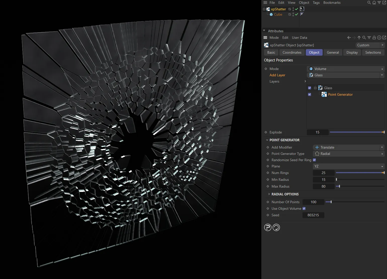
Glass
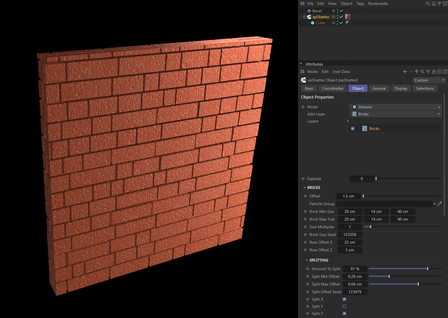
and Bricks.
Each type will result in a different pattern of shattering.
If you add too many layers, it may slow down the computer very considerably.
Each source layer will be added to the list above the menu.
You can enable and disable individual layers by checking or unchecking each layer in the list.
If you click a source layer to select it, there are several options that can be set for each layer, as explained below.
You can also add more point generators to the layer if desired.
Layers
Section titled “Layers”The list of source layers used to shatter the object.
You can add or delete layers from the list and enable/disable them using the check boxes.
There must be at least one layer with at least one point generator in this list to break an object.
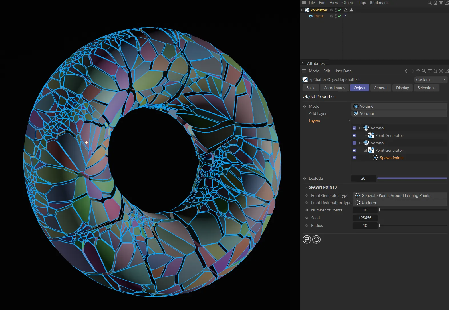
Here, a Torus is a child of xpShatter, with two Voronoi layers, both of which have Point Generators. Both point generators have different settings, the first is set to Mesh Bounding Box, and the second is set to Radial with a child Spawn Points layer.
Explode
Section titled “Explode”If you increase this value, the created fragments are separated from one another and pushed outwards.
This will increase the size of the bounding box of the object.
Animation to demonstrate the effect of increasing the Explode value.
Point Generator
Section titled “Point Generator”Add Modifier
Section titled “Add Modifier”Set as Translate, by default, this is the type of point modifier.
The alternative options are: Scale and Spawn Points.
Translate
Section titled “Translate”This modifier lets you move the shatter points along any of the three axes.
If you select the modifier, there are four additional parameters available.
Translate X, Translate Y, Translate Z
Section titled “Translate X, Translate Y, Translate Z”Adjust these sliders to move the points along the required axis.
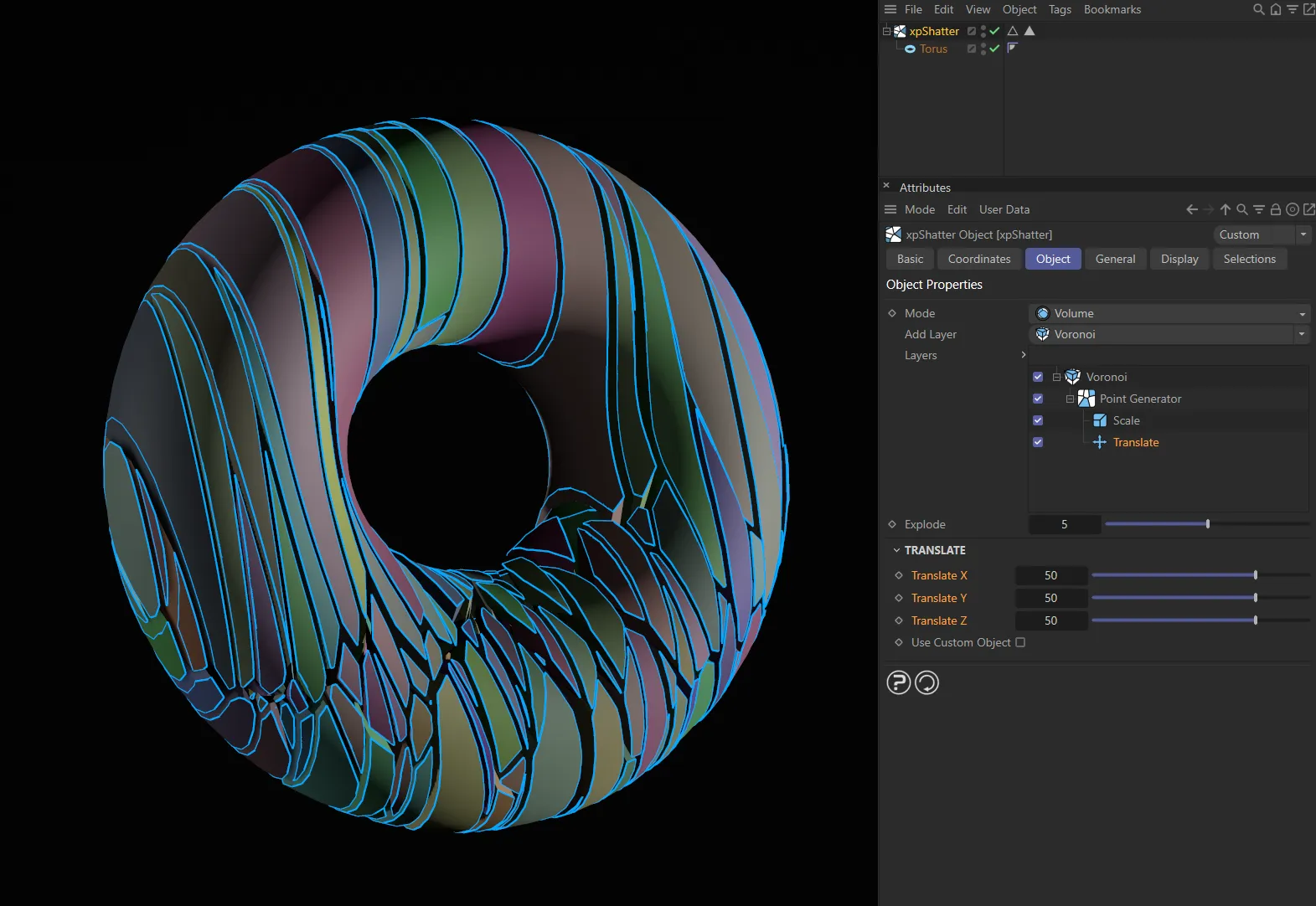
The Translate modifier in this layer system is pushing the effects of the Scale modifier upwards (with the Translate X, Translate Y and Translate Z values all at 50), revealing the unmodified Voronoi distribution at the bottom.
Use Custom Object
Section titled “Use Custom Object”If you enable this, a new link field appears: Custom Object.
You must drag and drop an object into this field then, when you move the object, the generated points will be moved in that direction.
You can use a null object for this; it doesn’t have to be a mesh or spline.
This modifier lets you scale the shatter point distribution up or down on any axis.
This modifier has three additional parameters.
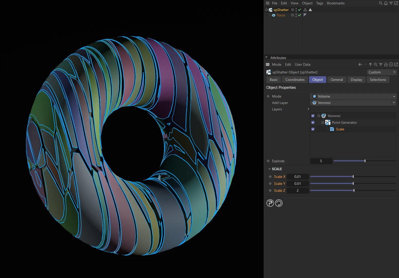
Here, the Scale modifier is set to significantly reduce the scale on both the X and Y axes (Scale X and Scale Y parameters), resulting in this slim shatter pattern.
Scale X, Scale Y, Scale Z
Section titled “Scale X, Scale Y, Scale Z”Adjust these sliders to scale the points along the required axis.
Spawn Points
Section titled “Spawn Points”This modifier produces additional shatter points in the object, so giving greater detail in the shattering.
There are no additional parameters with this modifier setting.
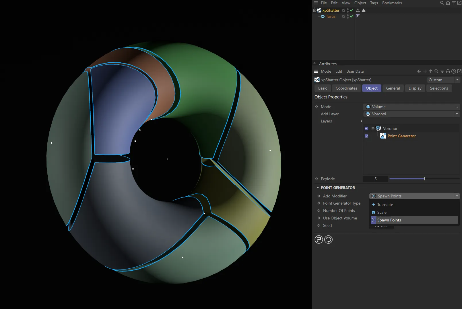
In this first image, Spawn Points is being selected in the Add Modifier parameter.
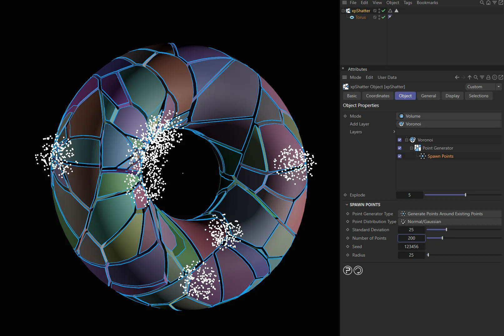
Once added, with Point Generator Type set at Generate Points Around Existing Points, the points are all visible here.
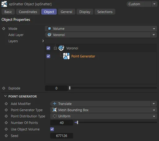
Point Generator Type
Section titled “Point Generator Type”Set as Mesh Bounding Box, by default.
The alternative settings are: Mesh Surface, xpPointContainer, Shader and Radial.
Each type has its own parameter options but there are three parameters which are available with all four type settings.
Number of Points
Section titled “Number of Points”The number of additional shatter points to be generated.
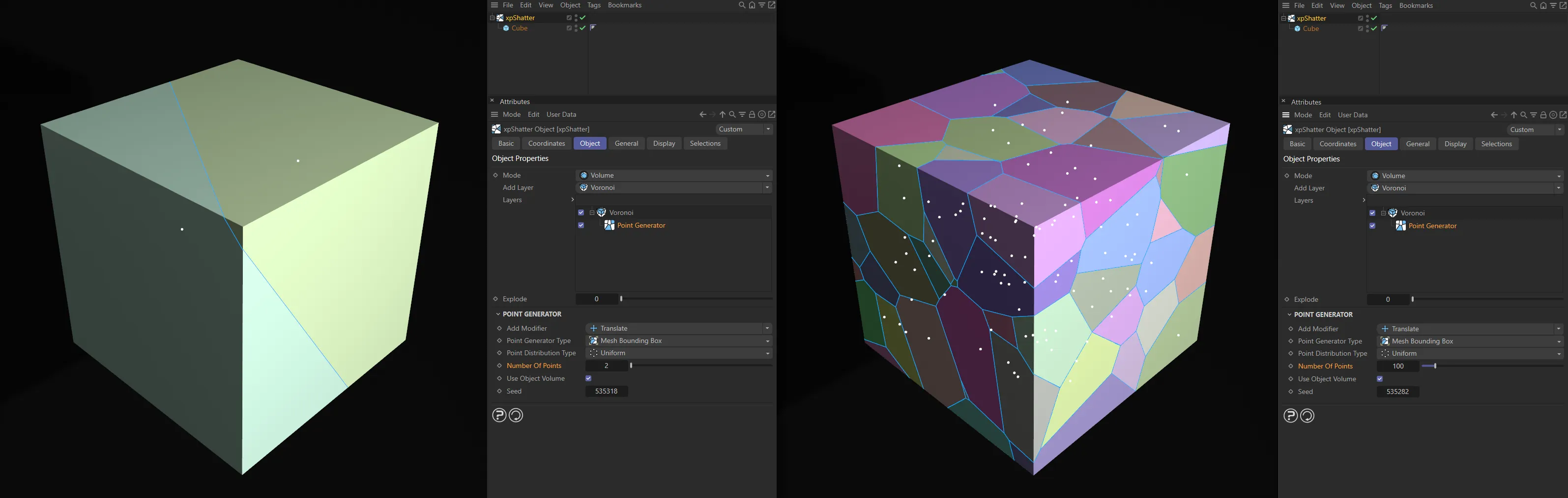
Number of Points set at 2, in the left-hand image, raised to 100, on the right.
Use Object Volume
Section titled “Use Object Volume”Enabling this will restrict the points to the volume of the source object.
A random seed used when generating the additional points.
Mesh Bounding Box type
Section titled “Mesh Bounding Box type”The bounding box of the mesh is used to calculate the shatter points.
This type has one additional parameter option available.
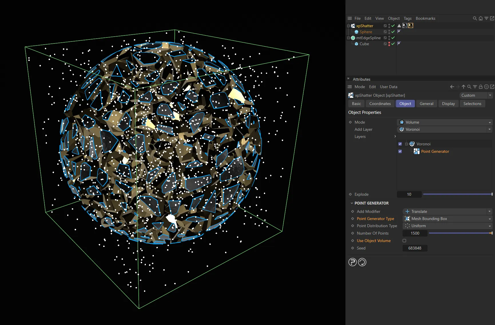
A Cube has been used here to give a visual demonstration of the bounding box, with Point Generator Type set to Mesh Bounding Box and points filling the volume of this area.
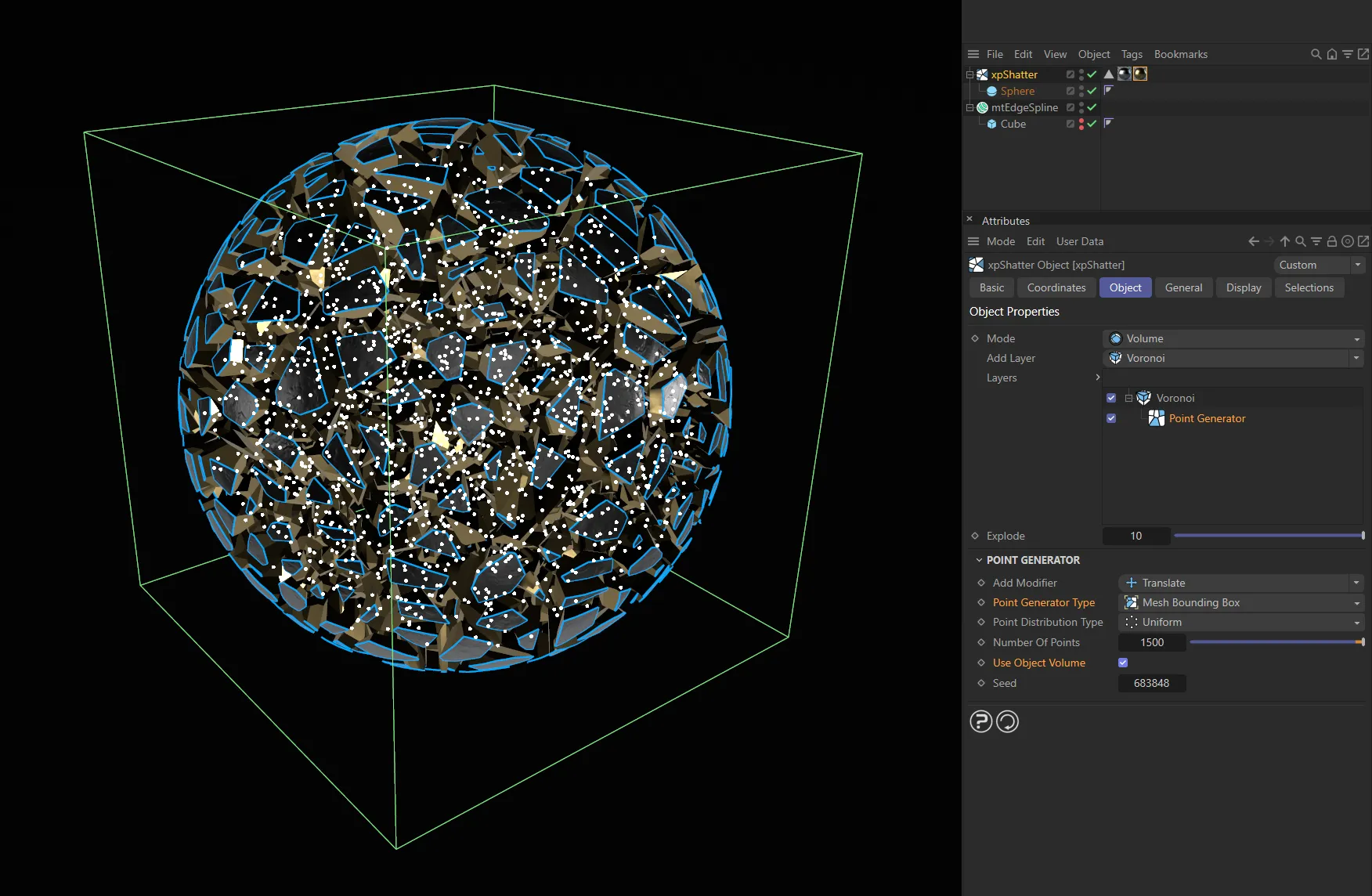
In this second image, Use Object Volume is enabled, restricting the points to the volume of the source object.
Point Distribution Type
Section titled “Point Distribution Type”Set as Uniform, by default, these are different algorithms for distributing the additional points.
The alternative is Normal/Gaussian.
Mesh Surface type
Section titled “Mesh Surface type”Calculation of the shatter points is confined to the mesh surface.
There are no additional parameter options available.
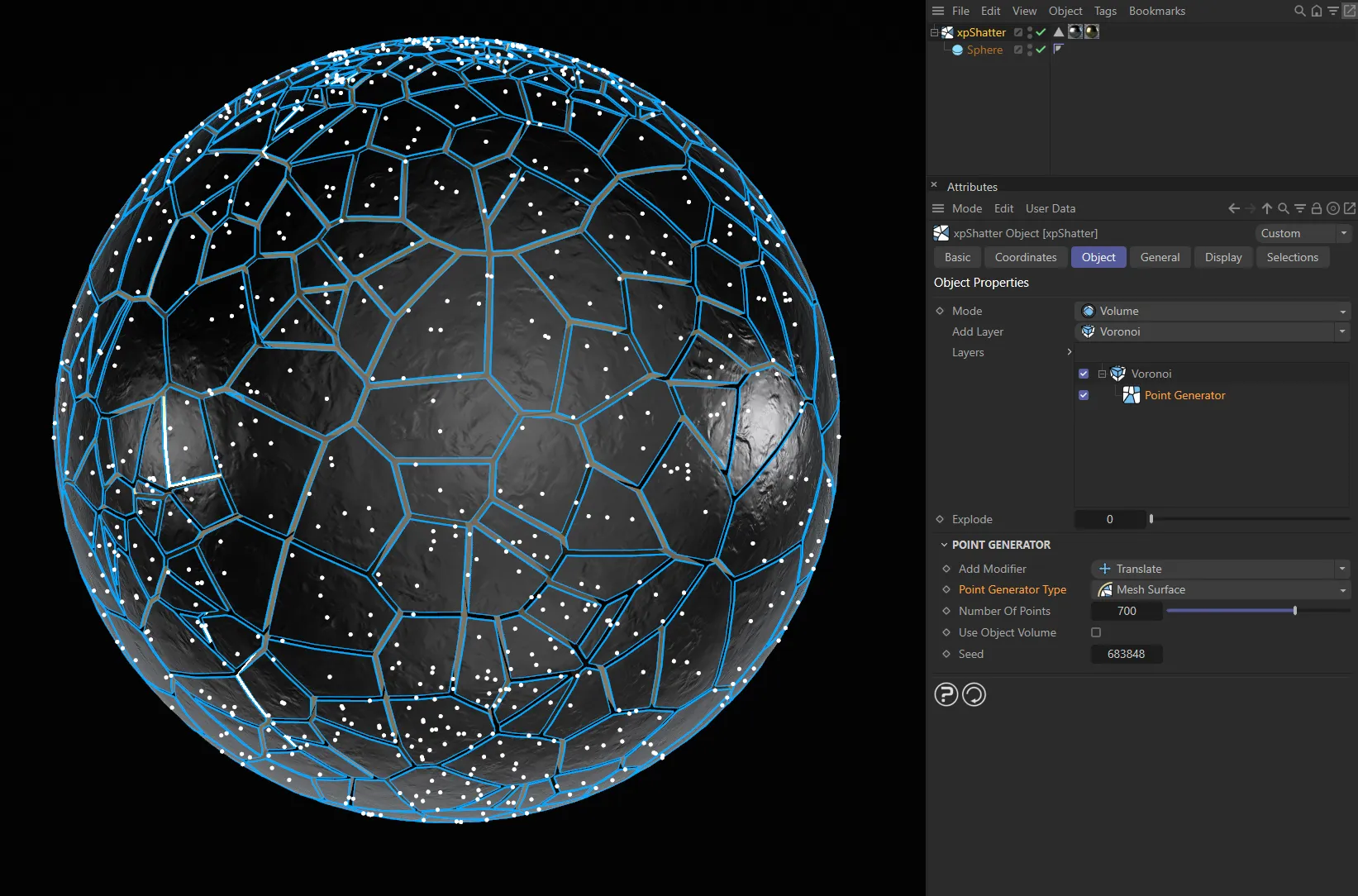
With Point Generator Type set as Mesh Surface, the points are generated on the surface of the source object.
xpPointContainer type
Section titled “xpPointContainer type”When you have a container, the points are generated within the container’s field of effect.
If you move the container around, the shattering effect will follow the container.
There are two additional parameter options available.
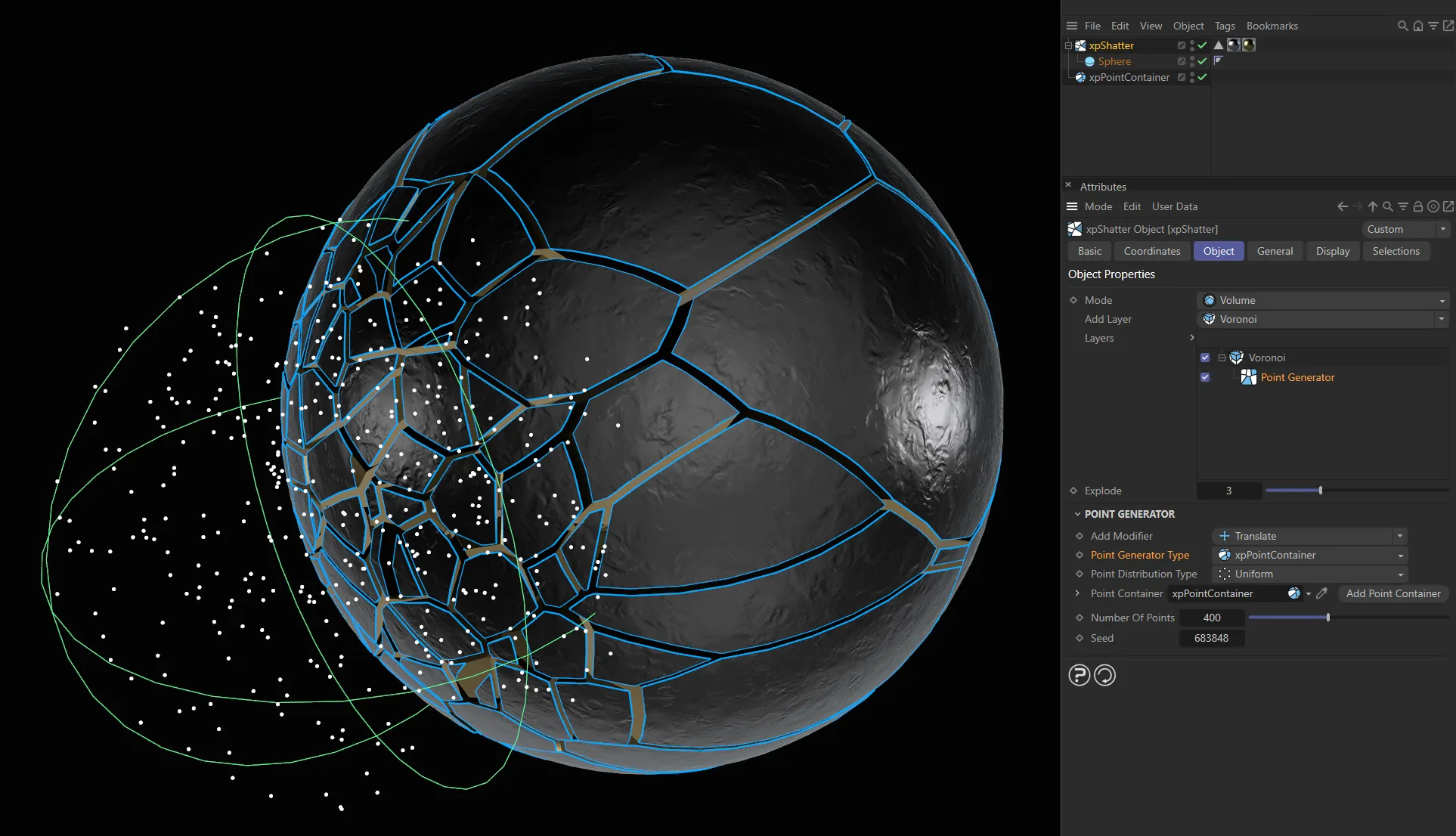
Above, with Point Generator Type set at xpPointContainer, the points are being generated within the container’s field of effect.
Point Distribution Type
Section titled “Point Distribution Type”Set as Uniform, by default.
As above, these are different algorithms for distributing the additional points.
The alternative is Normal/Gaussian.
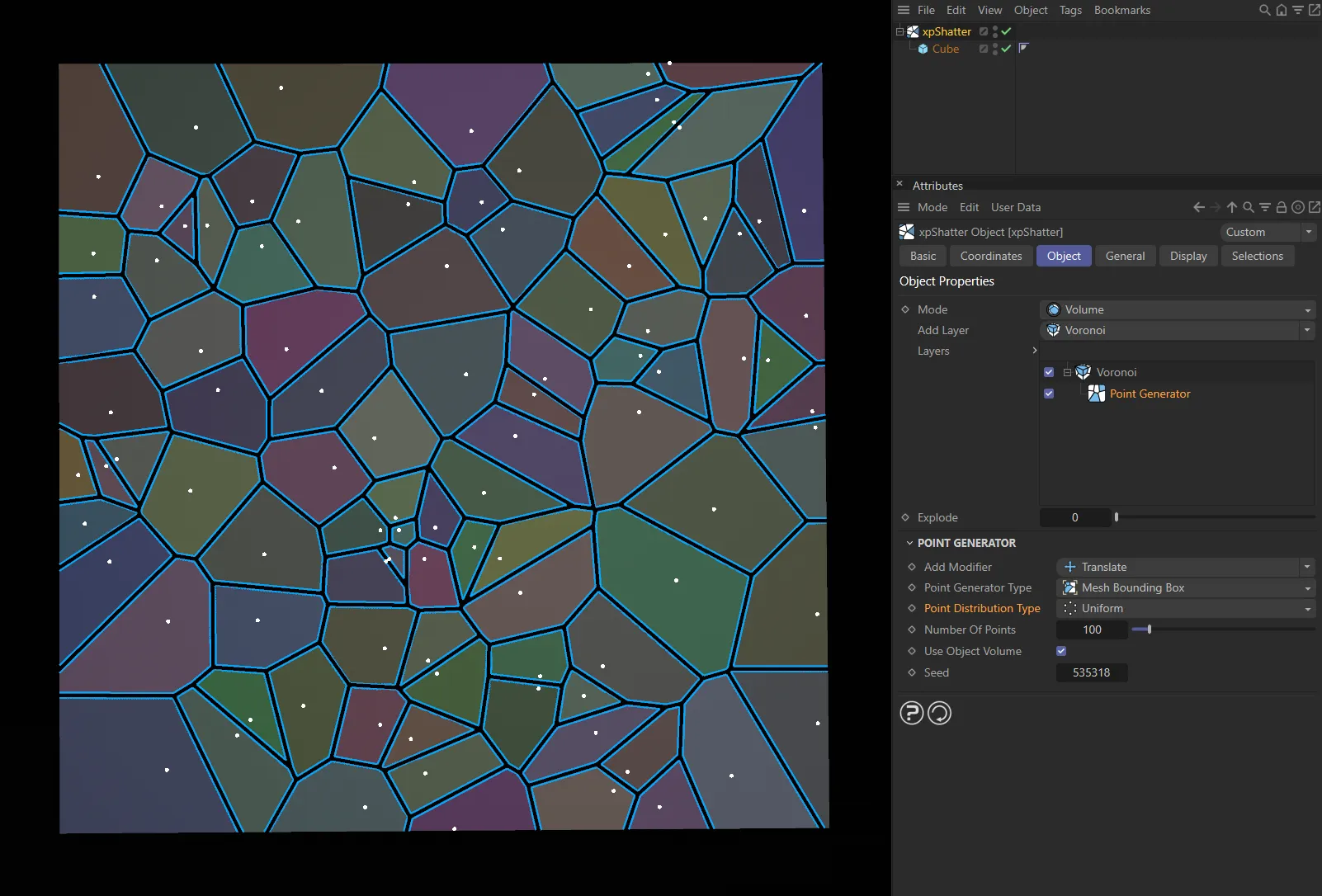
Point Distribution Type set as Uniform.
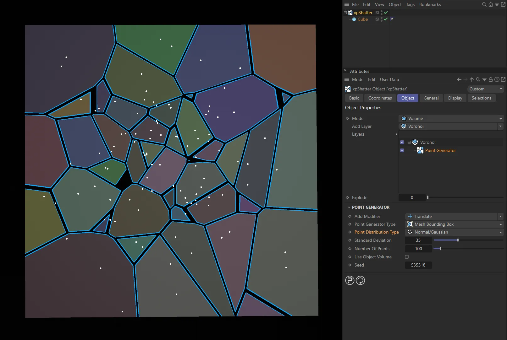
In this image, the Point Distribution Type is the alternative setting of Normal/Gaussian.
Point Container, Add Point Container
Section titled “Point Container, Add Point Container”Click the button to create an xpPointContainer and add it to the link field.
Alternatively, simply drag an existing container into the link field.
Shader type
Section titled “Shader type”A shader is used to generate the shatter points.
There are three additional parameter options available.
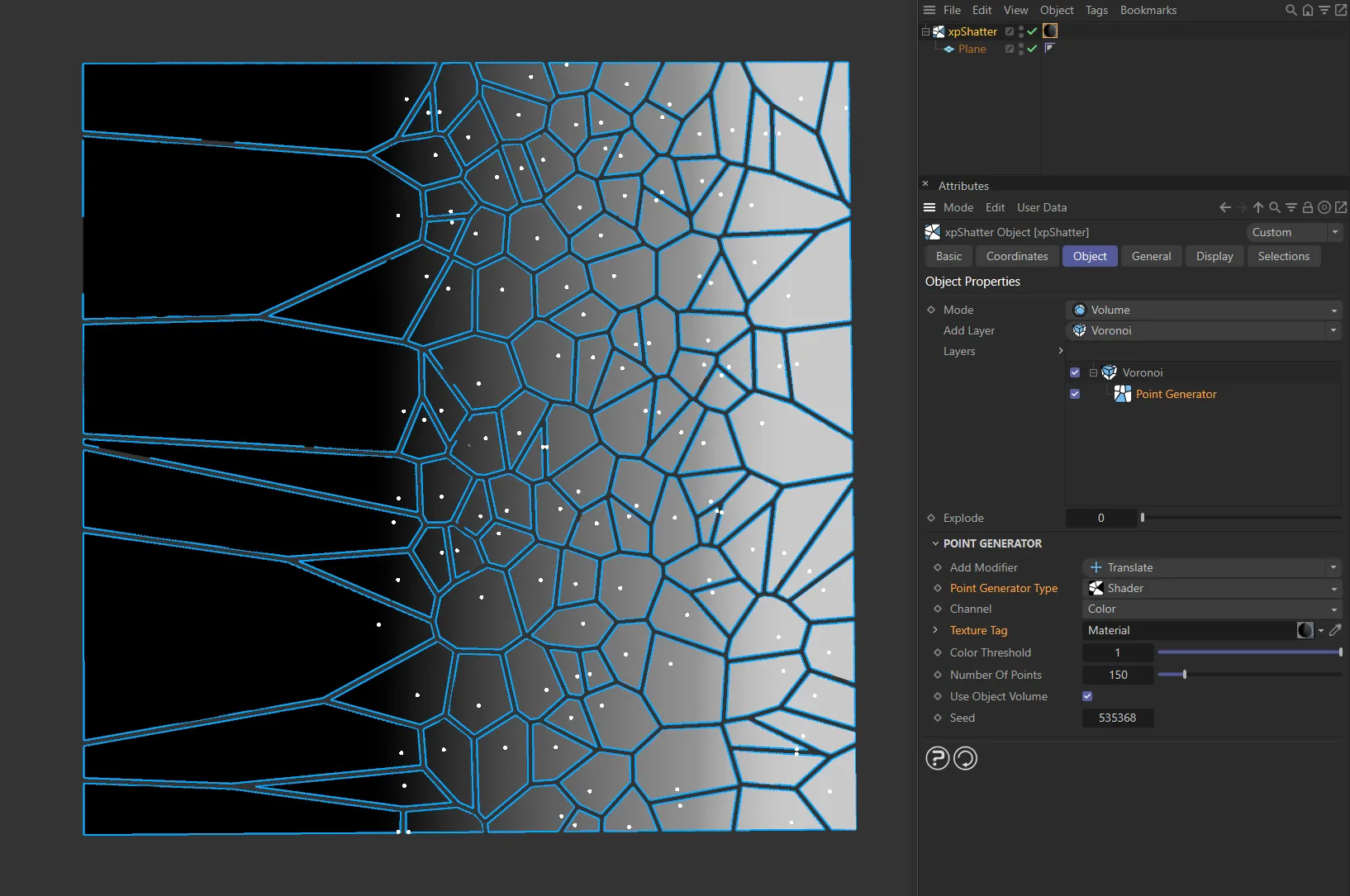
A shader is being used here, to generate the shatter points, with Point Generator Type set as Shader.
Channel
Section titled “Channel”The drop-down arrow reveals the usual Cinema 4D Shader types.
Texture Tag
Section titled “Texture Tag”You can drag a texture tag into this link field.
Color Threshold
Section titled “Color Threshold”The brightness of a color must exceed this value to be used in the point generation.
Radial type
Section titled “Radial type”Sets the additional points in a radial pattern.
The algorithm generates a series of concentric rings, which resembles the appearance of broken glass.
There are four other parameter options available, plus a drop down arrow, which offers two bias curves.
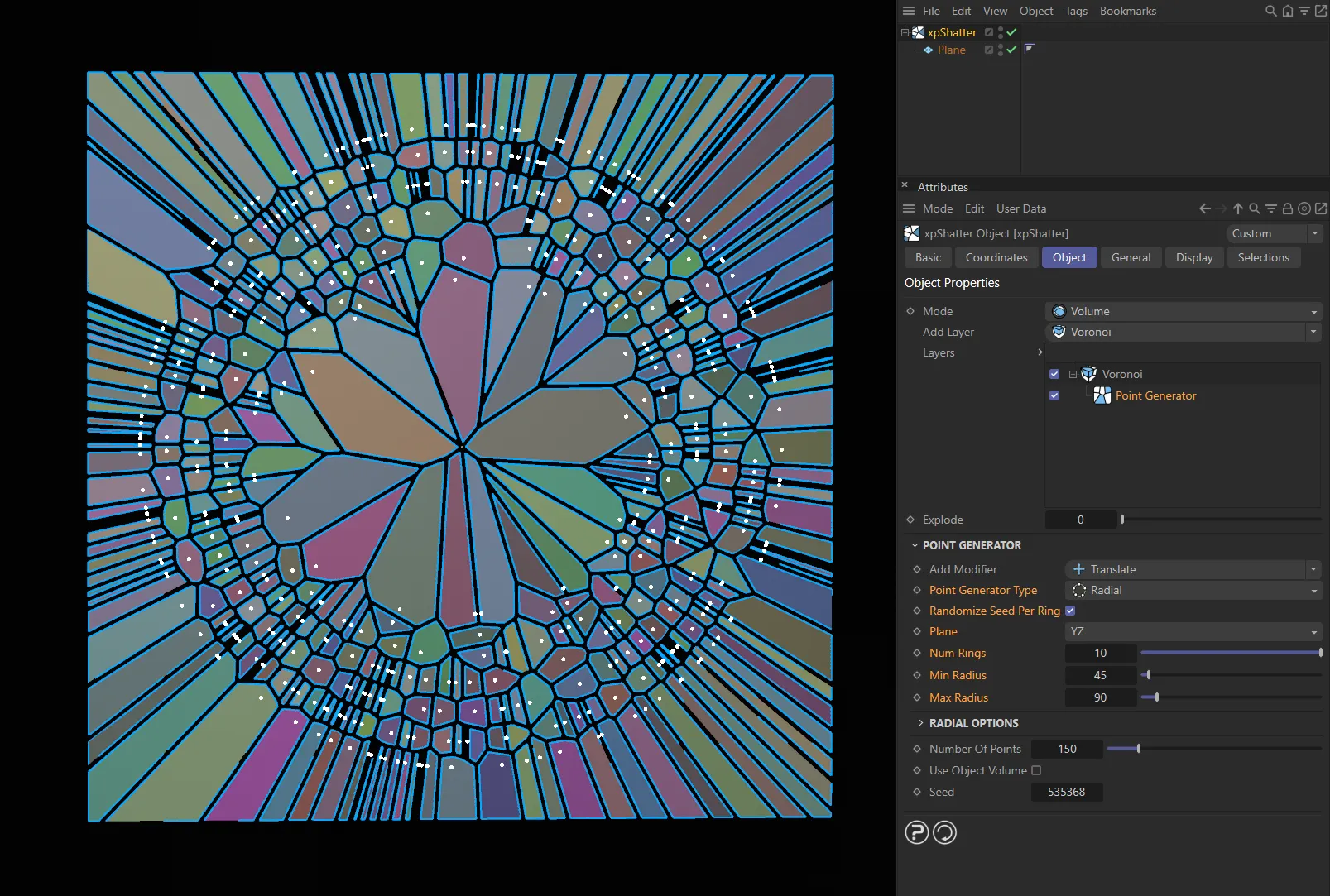
Point Generator Type set as Radial, giving the appearance of broken glass.
Randomize Seed Per Ring
Section titled “Randomize Seed Per Ring”If enabled, the seed used for each ring is randomized.
This gives a less regular result than if the seed is not randomized.
This kind of shattering can only take place in one plane, so this menu enables you to select which plane to use.
The choices are the XY, YZ or XZ planes.
Num Rings
Section titled “Num Rings”The number of rings to generate.
Min Radius
Section titled “Min Radius”The minimum radius of each ring; it can be greater than this, of course.
Max Radius
Section titled “Max Radius”The maximum radius of each ring; it can be smaller than this.
Radius Bias
Section titled “Radius Bias”This controls how the radius of each ring is set between the minimum and maximum radius values.
For example, with the default spline, the left hand point controls the radius of the innermost ring so, as this value increases from zero, the inner ring will expand and all other rings will expand also, to maintain distance between the rings.
If it is set to the same value as the right hand point, this effectively gives all the rings the same radius (the same as if Min Radius and Max Radius are set to the same value) and the rings disappear, leaving only the center point.
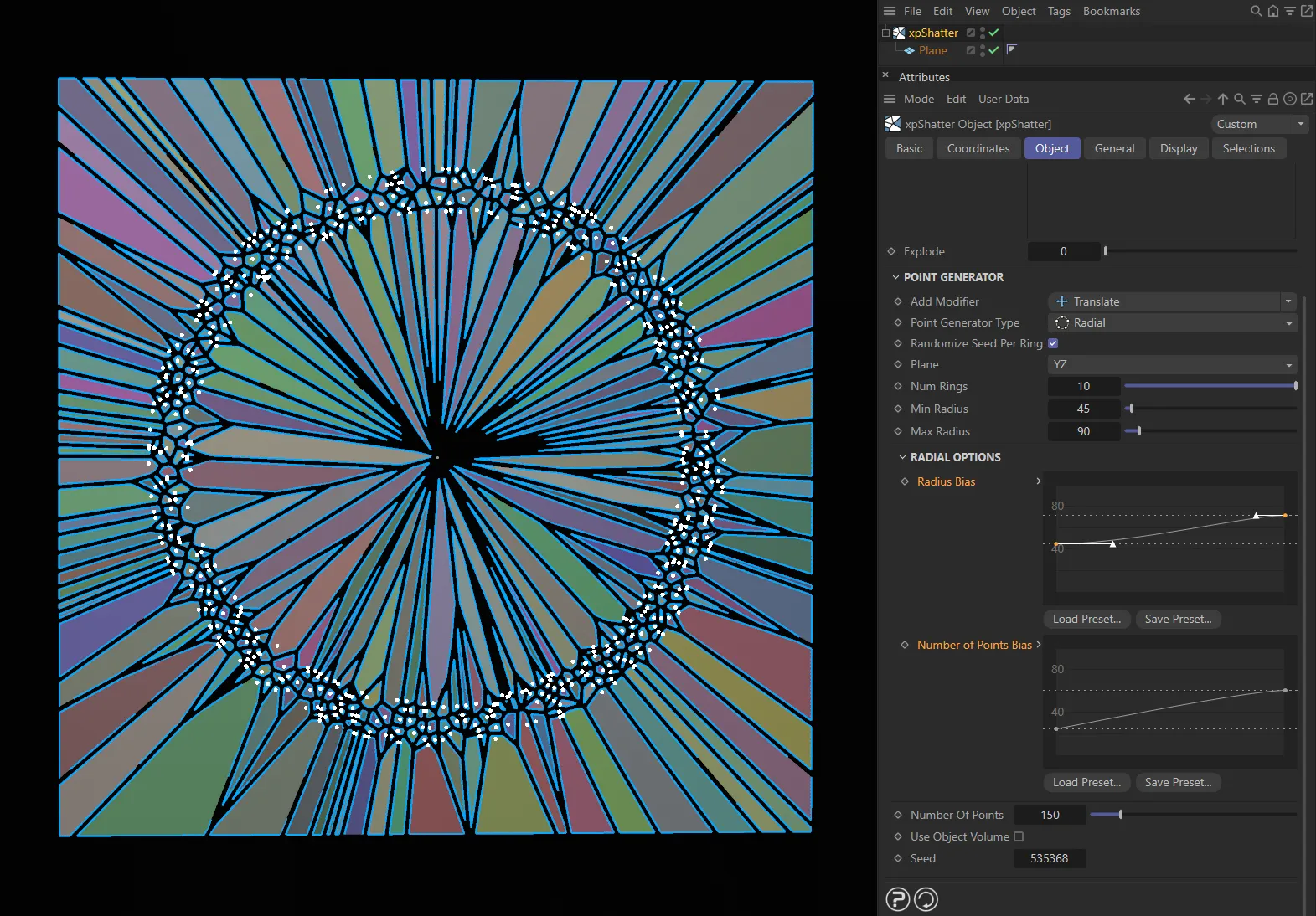
Here, the Radius Bias and Number of Points Bias splines have been manipulated to art-direct the shatter pattern above.
Number of Points Bias
Section titled “Number of Points Bias”This controls how the Num Points setting is used for each ring.
For example, with the default spline the number of points is set to the maximum value for the innermost ring but fewer points are used for the outer rings.
Load Preset, Save Preset
Section titled “Load Preset, Save Preset”You can load in preset curves or save your customized bias settings, using the Load Preset and Save Preset buttons.
You are not simply restricted to the inbuilt point generator.
You can also add a mesh object, spline, or an xpEmitter into the Layers list as a child of a source layer.
Animation to show xpEmitter being dragged and dropped into the Layers list and the subsequent effect of increasing the Birthrate and Speed parameters.
Use Object Points
Section titled “Use Object Points”If enabled, the vertices of the object (if it has some) are used to break the mesh.
Use Object Hierarchy Points
Section titled “Use Object Hierarchy Points”If enabled, the vertices of any child objects of the object will also be used to generate shatter points.
Otherwise, child objects are ignored.
Use Object Cached Hierarchy Points
Section titled “Use Object Cached Hierarchy Points”If the object is a generator object such as a MoGraph Cloner, enabling this will cause the vertices of the clones to be used to generate shatter points.
Otherwise the cloner will be ignored (since it has no vertices of its own).
Point Type
Section titled “Point Type”For polygon objects there is only one option in this menu, Use Object Points, so this cannot be changed; the vertices of the object are used to generate the shatter points.
For spline objects there is another option, Generate Points Along Spline.
With this setting, there are three additional parameters available.
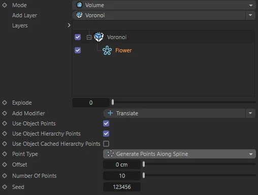
With a Flower spline having been dragged and dropped into the Layers list and Point Type set to Generate Points Along Spline.
Offset
Section titled “Offset”Increasing this value will offset the shatter points away from the spline.
The direction and distance is random and can be changed by altering the Seed value.
Number of Points
Section titled “Number of Points”The number of shatter points to be generated along the spline.
If the Offset value is greater than 0 (zero) cm, this is the seed value for the random offset of the shatter points.
Layer Options
Section titled “Layer Options”The following three parameters are common to all four layer types (Voronoi, Wood, Glass and Bricks).
Offset
Section titled “Offset”This is very similar to the Explode setting but produces a separation between fragments by reducing fragment size, so the overall size of the object does not increase.
This animation shows the effect of the Offset parameter.
Particle Group
Section titled “Particle Group”If you are using an emitter you can drag a particle Group object into this field.
All particles emitted by the emitter, when it is in controlled-only mode, will then be in this group, regardless of any groups that may be in the Groups list of the emitter.
Add Generator
Section titled “Add Generator”Clicking this Point Generator button will add an additional Point Generator to the layer which you have highlighted.
The Bricks layer has the following additional settings.
Brick Min Size
Section titled “Brick Min Size”Sets the minimum size of the bricks on all three axes, dependent on the space available on the child object being shattered.
Brick Max Size
Section titled “Brick Max Size”Sets the maximum size of the bricks on all three axes, dependent on the space available on the child object being shattered.
Size Multiplier
Section titled “Size Multiplier”Increases, or decreases, the global scale of the bricks’ size.
Brick Size Seed
Section titled “Brick Size Seed”Applies a random pattern to the overall look, dependent on the values set.
Row Offset X
Section titled “Row Offset X”Offsets the rows of bricks in the X axis.
Row Offset Z
Section titled “Row Offset Z”Offsets the rows of bricks in the Z axis.
Splitting
Section titled “Splitting”These parameters are only available for the Bricks layer.
They act to split the geometry of the bricks themselves.
Amount to Split
Section titled “Amount to Split”The percentage of bricks split on the axis selected.
This animation demonstrates the Splitting parameters.
Split Min Offset, Split Max Offset
Section titled “Split Min Offset, Split Max Offset”The minimum and maximum offset of the splitting on the individual brick.
For example, if both of these values are set at 0.5cm, then every brick (subject to the Amount to Split percentage selected) will be split directly in half.
Split Offset Seed
Section titled “Split Offset Seed”Sets a random split pattern across the entire surface, based on the other settings in this section.
Spit X, Split Y, Split Z
Section titled “Spit X, Split Y, Split Z”Enable these settings to split the bricks on the axis/axes you require.
The parameters above will have no effect unless at least one of these boxes is ticked.
Trigger tab
Section titled “Trigger tab”For each layer, you can use this menu to set when the shattering should take place.
Depending on the Trigger option, a number of other settings become available.
Trigger
Section titled “Trigger”There are five options: Always, Time, Speed, Collision and Volume.
Always
Section titled “Always”The object is shattered immediately.
There are no parameters for this option.
Shattering will take place after a specified time has elapsed.
The time can be set in the Time field, which becomes available with this option.
With the Trigger set to Time, in this animation, once the Time value of 50 frames is reached, the shatter is triggered.
Time, Time Variation, Seed
Section titled “Time, Time Variation, Seed”Set the frame when you want shattering to take place.
Variation can be added to this by using the Time Variation setting.
The Seed value is the seed for the random variation which is added.
The ‘speed’ in this case refers to particle speed.
To use this option, you must have an emitter in your scene and something (such as an xpGravity or xpTurbulence modifier) to give some speed to the particles.
For best results, you could also add an xpDynamics tag to the xpShatter object; if you don’t, the particles will still move and the object will shatter, but will not look as realistic.
As the particles are moved, their speed increases and if they exceed the speed in the Speed parameter, the object will shatter.
You can have more than one layer set to Speed with different shattering speeds, if you need them.
In this animation, an xpSpeed modifier is incrementally adding speed to the movement of the Sphere with each frame. Once it reaches the Speed value of 135cm, the shattering occurs and the fragments are forced away from each other due to the Push settings in the Sphere’s xpDynamics tag.
Speed, Speed Variation
Section titled “Speed, Speed Variation”The Speed setting is the speed which the linked particles must exceed for shattering to occur.
Variation can be added to this by using the Speed Variation setting.
Collision
Section titled “Collision”With this option, as with the Speed trigger you need an emitter in your scene.
Fragmentation will then occur on collision between the particles and an object or with other particles.
You should add an xpDynamics tag to the Shatter object for realistic results.
Particle<->Particle, Particle<->Volume, xpBullet, Collision Speed, Speed Variation
Section titled “Particle<->Particle, Particle<->Volume, xpBullet, Collision Speed, Speed Variation”The first two boxes indicate whether shattering will occur when the linked particles collide with other particles and/or with a scene object.
Animation to demonstrate shattering with Particle <->Particle enabled. xpPPCollisions is present in the scene so that the system registers the collision.
If a scene object is used, it must have an xpCollider tag attached to it.
This animation demonstrates xpShatter with Particle <-> Polygons enabled and an xpDynamics tag attached. The xpCollider tag is ensuring that the collision is registered.
Alternatively, if you have an xpBullet object in your scene, you can enable the third box, xpBullet.
Here, xpBullet is enabled. An xpBullet Rigid Body tag is attached to the xpShatter and there is an xpBullet Collider tag on the collision geometry. The collision is being detected by this xpBullet system.
For shattering to occur the speed of the object, after collision, must exceed the value in Collision Speed.
By default this is set to 0 (zero), so that shattering occurs immediately on collision.
Variation can be added to this by using the Speed Variation setting.
Volume
Section titled “Volume”This setting requires an xpVolumeContainer.
When this is present, the object will shatter when it enters the volume of the container.
Volume Container, Add Volume Container
Section titled “Volume Container, Add Volume Container”Click the button to create an xpVolumeContainer and add it to the link field.
Alternatively, simply drag an existing container into the link field.
Details tab
Section titled “Details tab”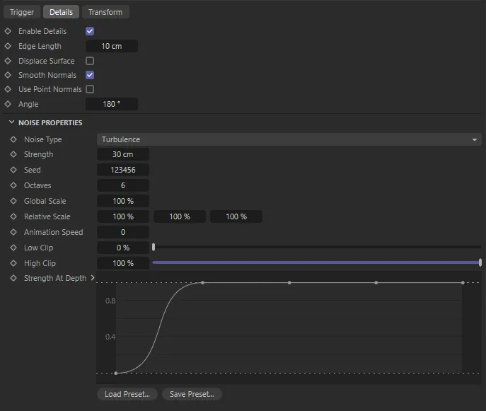
Details tab parameter options.
The Details tab enables a Noise filter to deform the fragmentation.
Enable Details
Section titled “Enable Details”Checking this box enables the filter.
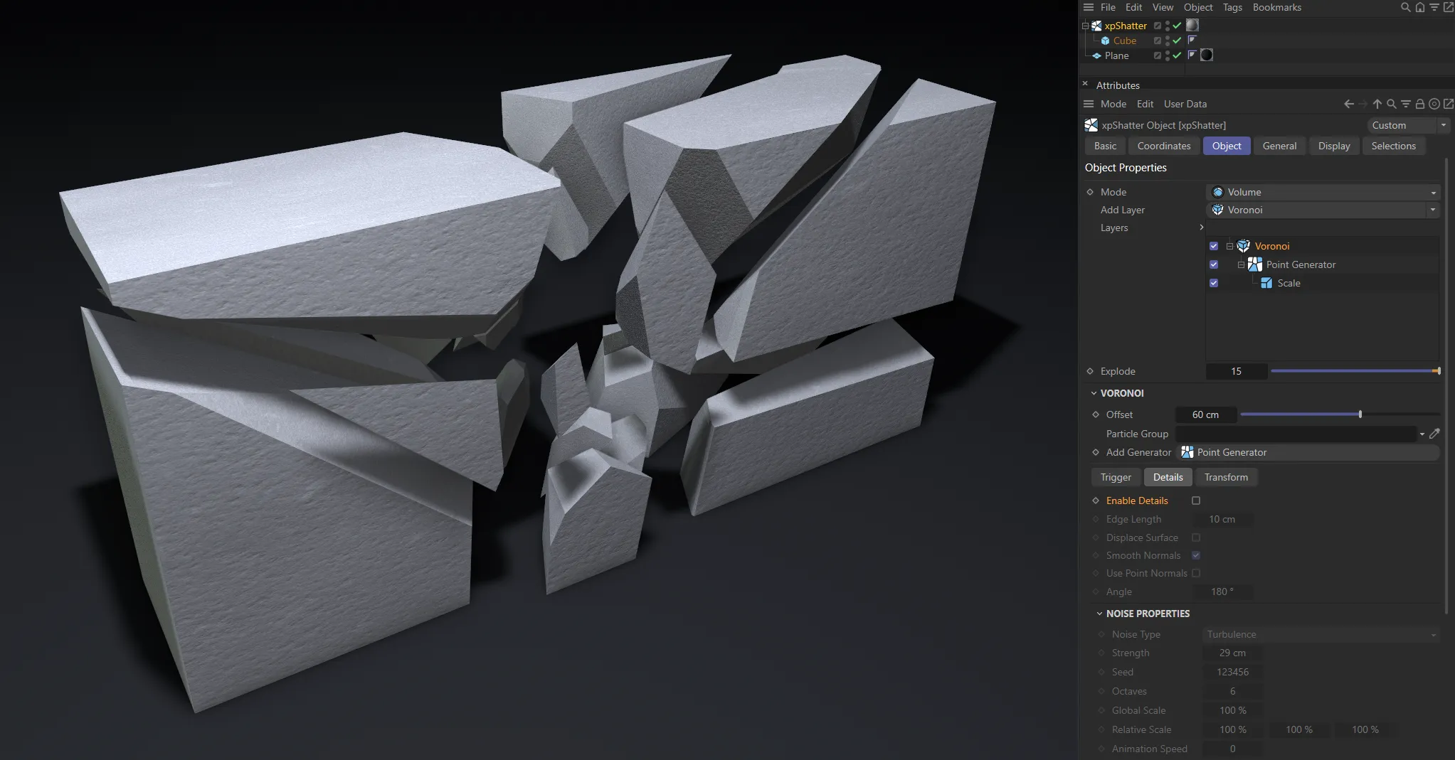
Enable Details is disabled in this image.
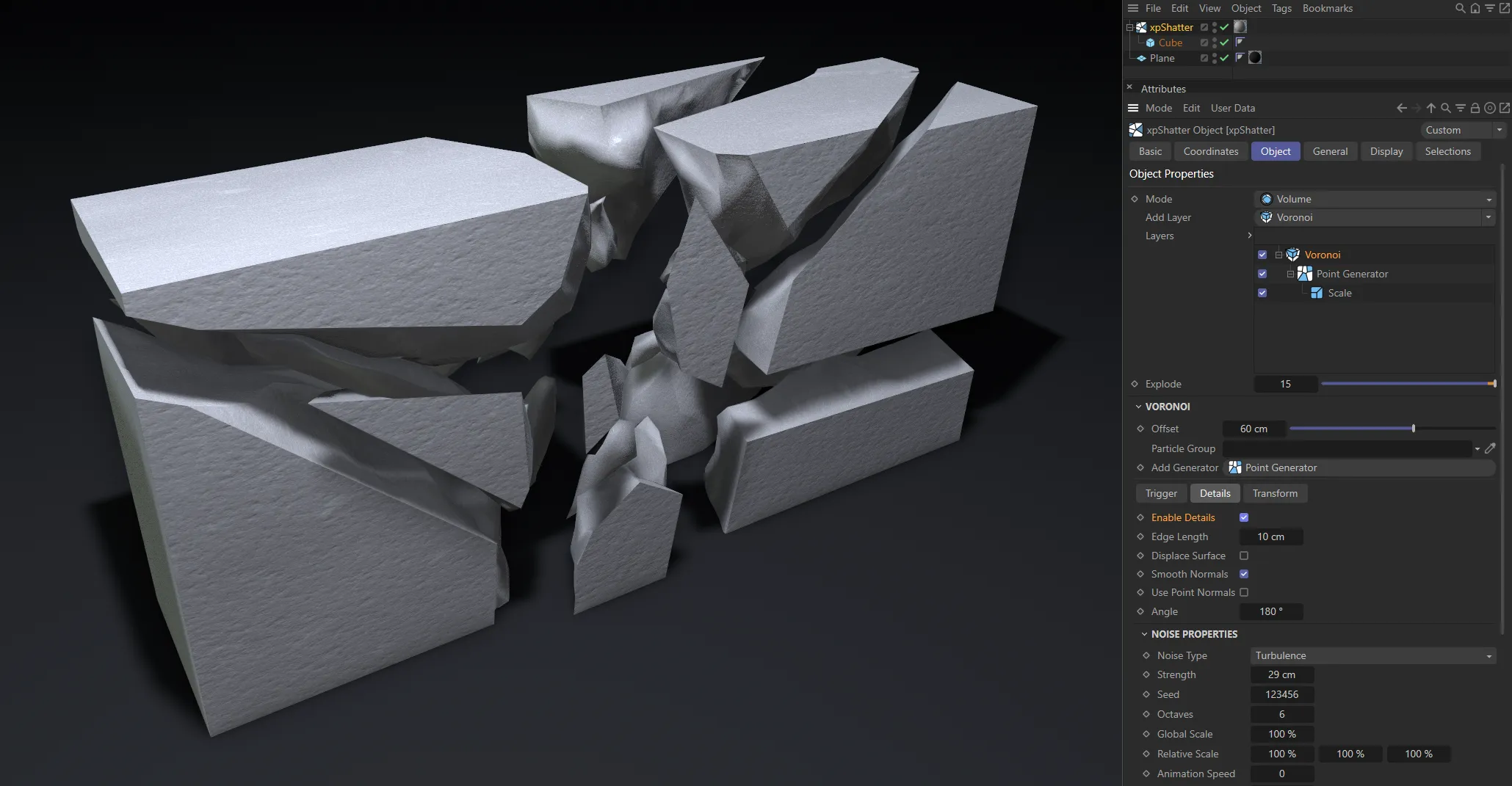
Enable Details is enabled in this image.
Edge Length
Section titled “Edge Length”This is the length of edges in the newly generated detail surface.
A lower Edge Length value will generate smaller polygons and, therefore, higher-quality detailing.
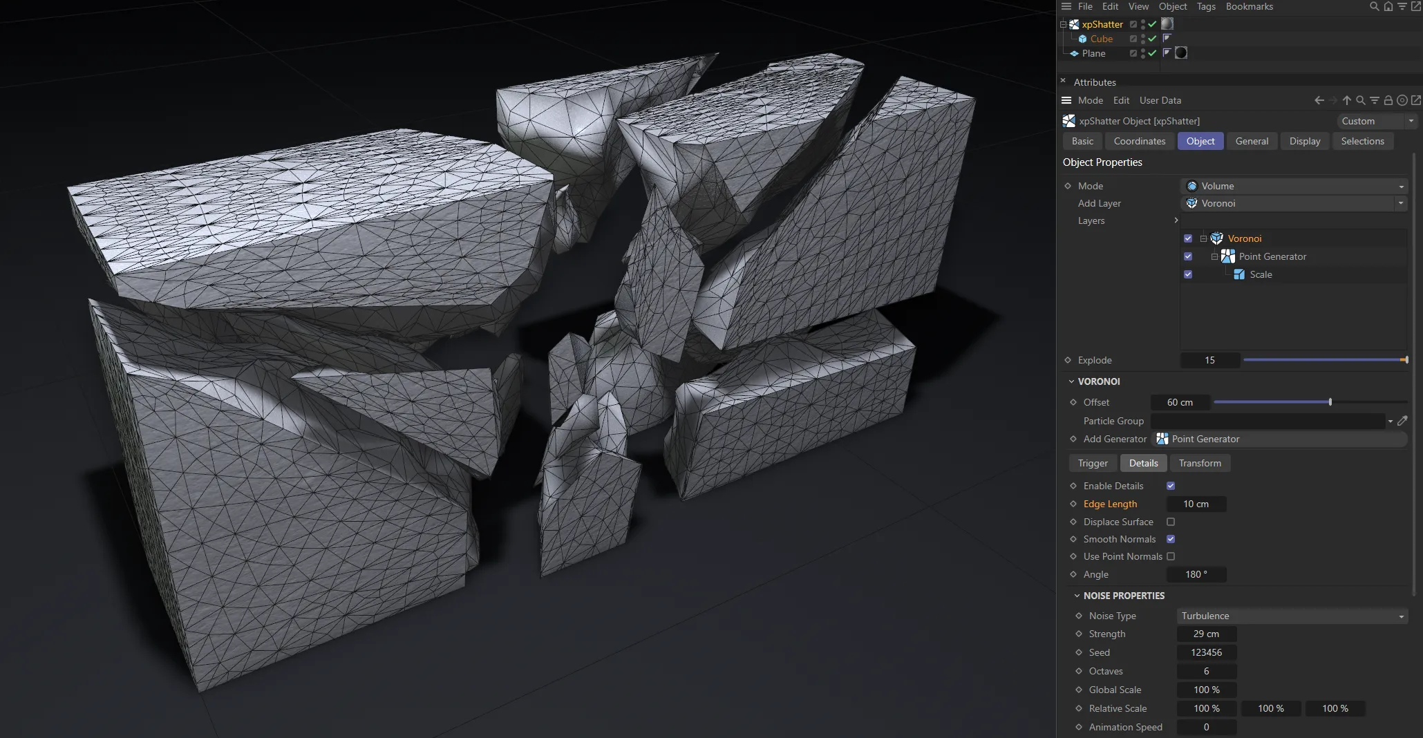
Edge Length is set at 10cm here.
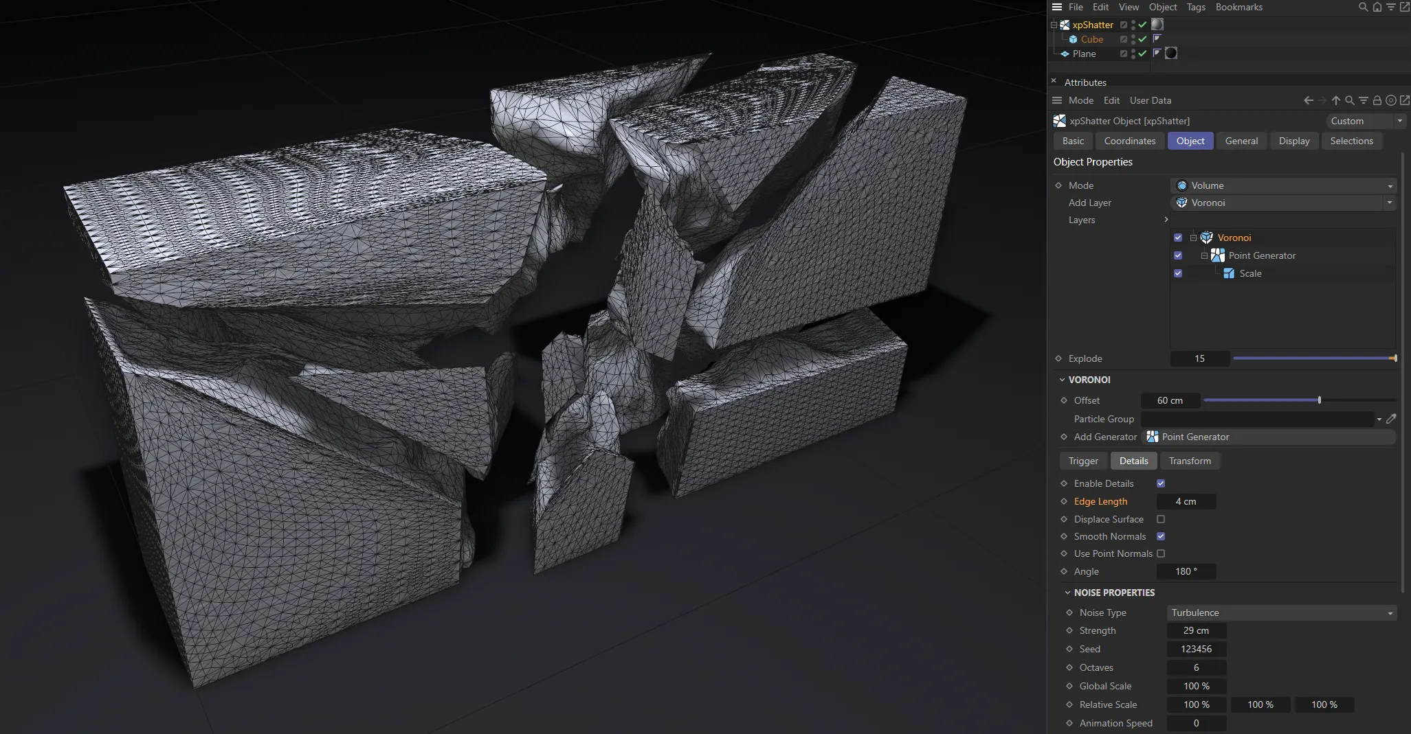
In this image, Edge Length is lowered to 4cm, generating smaller polygons, resulting in a much higher quality.
Displace Surface
Section titled “Displace Surface”When enabled, the fragmentation is displayed on the object’s surface.
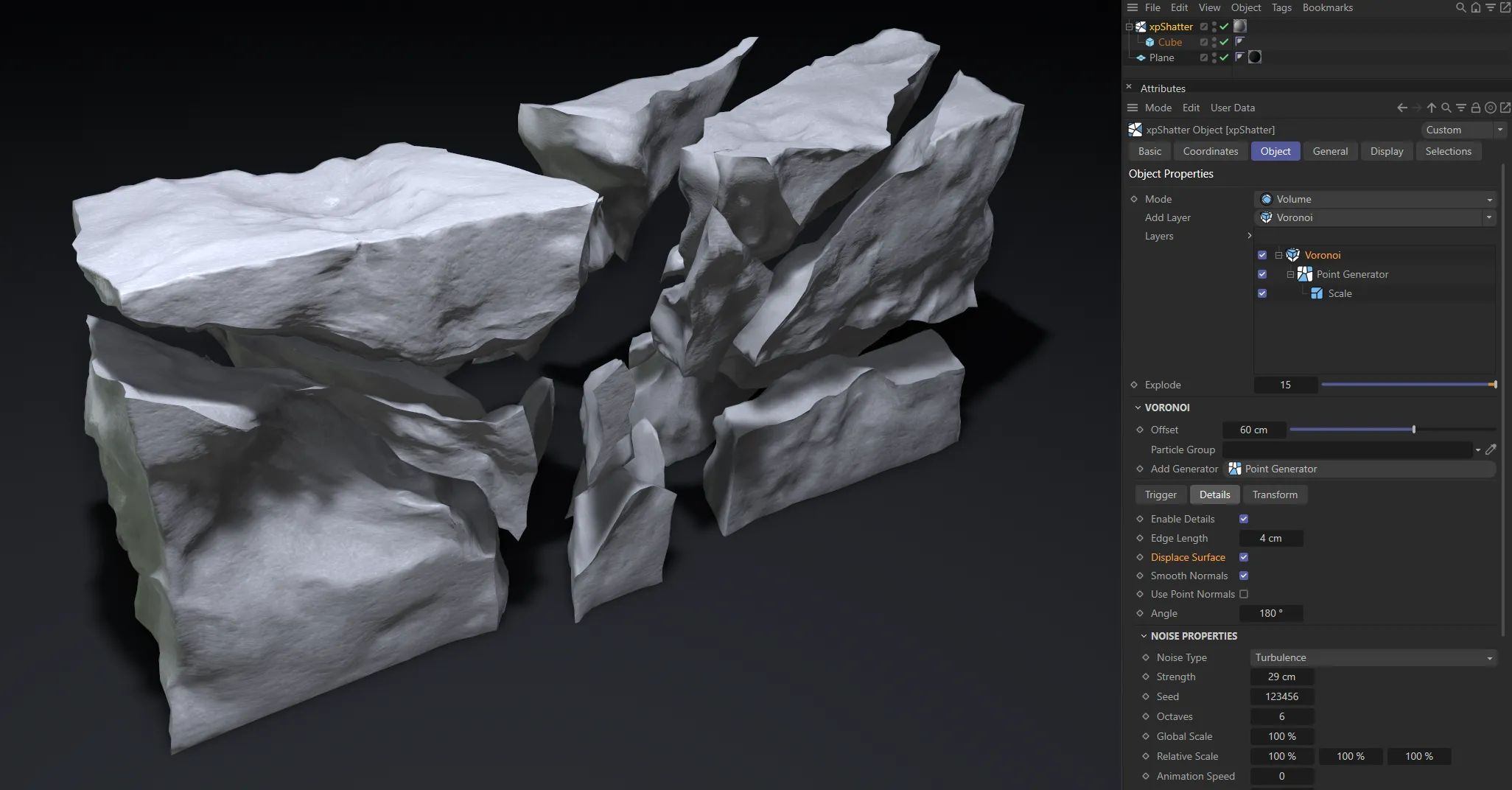
Displace Surface enabled, with fragmentation visible on the object’s surface.
Smooth Normals
Section titled “Smooth Normals”This option smooths the newly created surface. There are two options for smoothing, Use Point Normals and Angle.
Use Point Normals
Section titled “Use Point Normals”This smoothing method retains the flat look of the shard’s faces, despite the surface being distorted by the detailing.
Not available when Use Point Normals is enabled, this setting adjusts the angle threshold, below which the edge of two adjoining faces is smoothed.
Noise Properties
Section titled “Noise Properties”Noise Type
Section titled “Noise Type”All the standard noise settings are available here.
Strength
Section titled “Strength”Set the strength of the noise.
Applies a random look to the settings.
Octaves
Section titled “Octaves”This parameter influences the frequency of the noise, creating more detail.
Global Scale
Section titled “Global Scale”This parameter controls the overall scale of the noise.
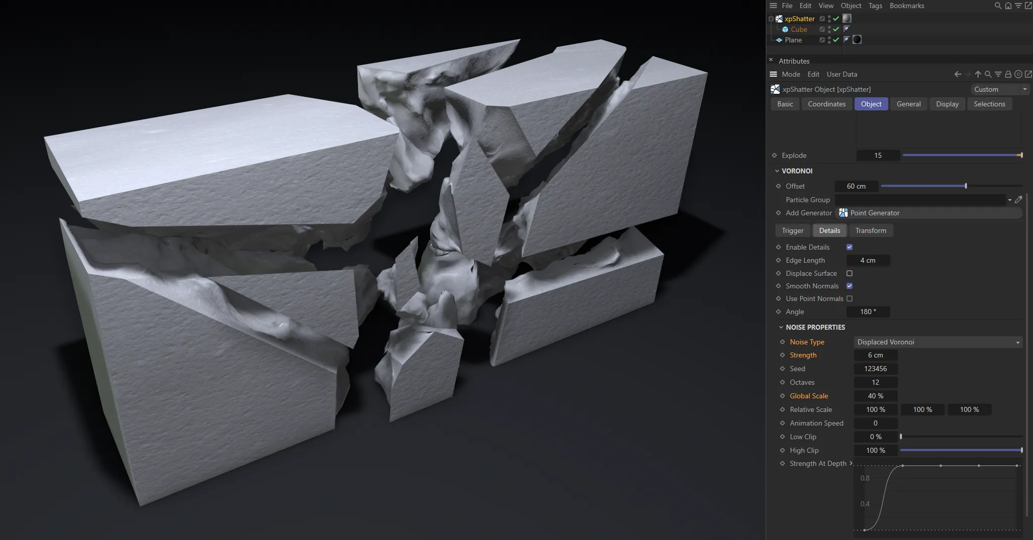
This image has Global Scale reduced to 40%, as well as a lower Strength setting and a Noise Type of Displaced Voronoi. The reduced global scale has decreased the noise pattern, resulting in finer detail deformation.
Relative Scale
Section titled “Relative Scale”By direct comparison to the Global Scale setting, this give you control over the X, Y and Z axes independently, allowing you to reduce the scale on separate axes, which can give way to interesting detailing styles.
Animation Speed
Section titled “Animation Speed”This parameter controls the animation speed of the noise used to generate the fragmentation.
If it is set to 0 (zero), no animation occurs and the fragmentation will not appear to move.
Low Clip, High Clip
Section titled “Low Clip, High Clip”Controls the maximum and minimum noise levels.
Strength At Depth
Section titled “Strength At Depth”The Y axis is the strength of the deformation and the X axis is the depth, from the edge of the shattered piece to the middle.
The drop-down arrow reveals additional parameters here.
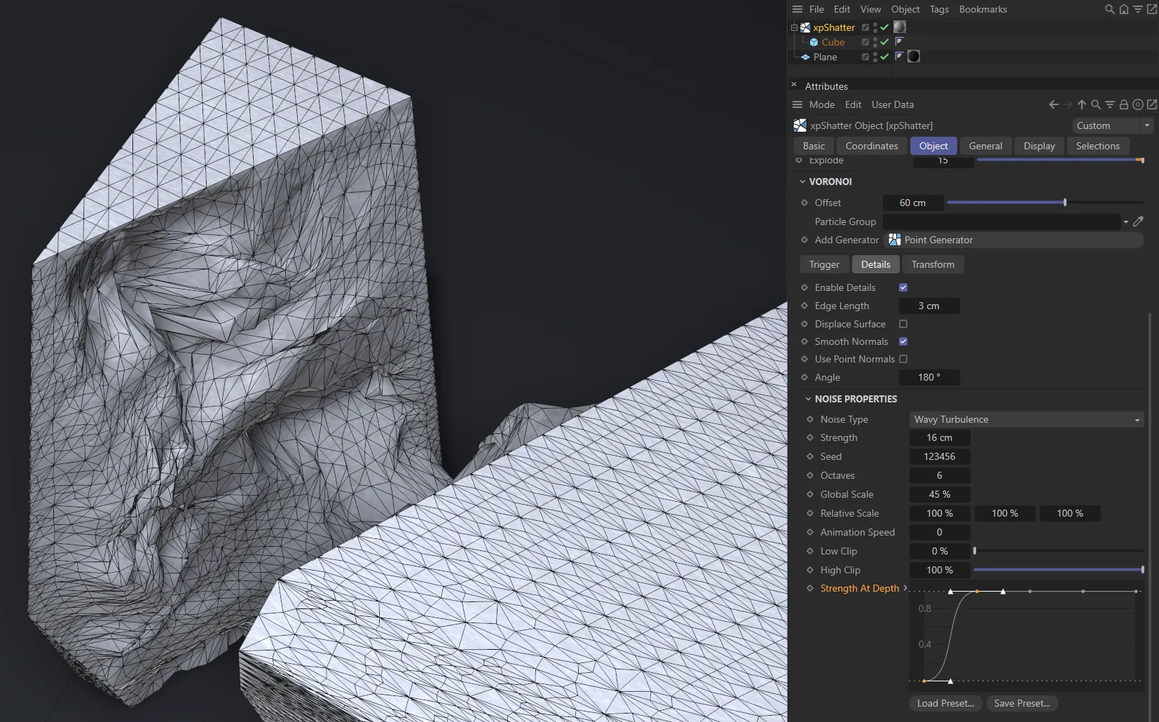
In this image, with the Strength At Depth default setting, there is an immediate increase of strength, with no displacement on the edges.
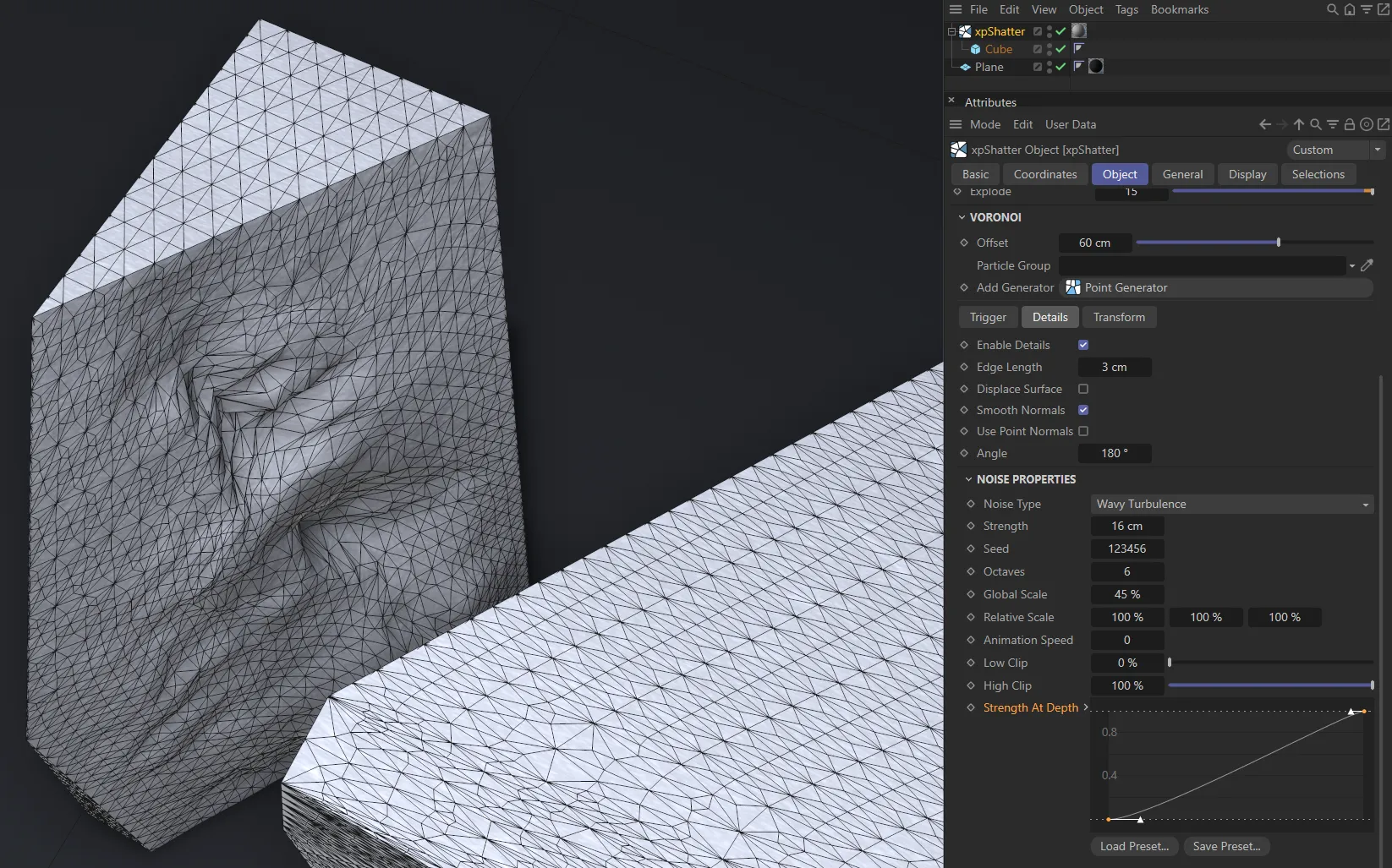
Here, the Strength At Depth spline curve shows a more gentle increase of strength towards the centre of the piece.
Transform tab
Section titled “Transform tab”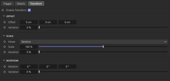
Transform tab parameter options.
Offset
Section titled “Offset”Offset
Section titled “Offset”Sets offsets on all three axes.
Variation
Section titled “Variation”Offers a degree of variation of the Offset levels.
Set as Relative, by default.
The alternative setting is Absolute.
Relative
Section titled “Relative”In Relative mode you can increase or decrease the entire scale with the percentage slider.
You can also add variation to vary the scales if you have multiple child objects.
Absolute
Section titled “Absolute”Absolute scale gives you the per-axis scale control, rather than a single, global scale control.
Sets Scale values on each of the three axes.
Variation
Section titled “Variation”Adds a variation to the levels of scale set.
Rotation
Section titled “Rotation”Rotation
Section titled “Rotation”Sets rotation on all three axes.
Variation
Section titled “Variation”Gives a degree of variation between rotation levels.
Display tab
Section titled “Display tab”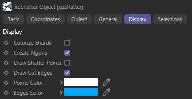
Display tab menu.
Colorize Shards
Section titled “Colorize Shards”Activating this parameter, applies a different color to each shard.

Colorize Shards is enabled in the right-hand image.
Create Ngons
Section titled “Create Ngons”Enabling this parameter creates Ngons (polygons with five or more edges) on the shatter faces.
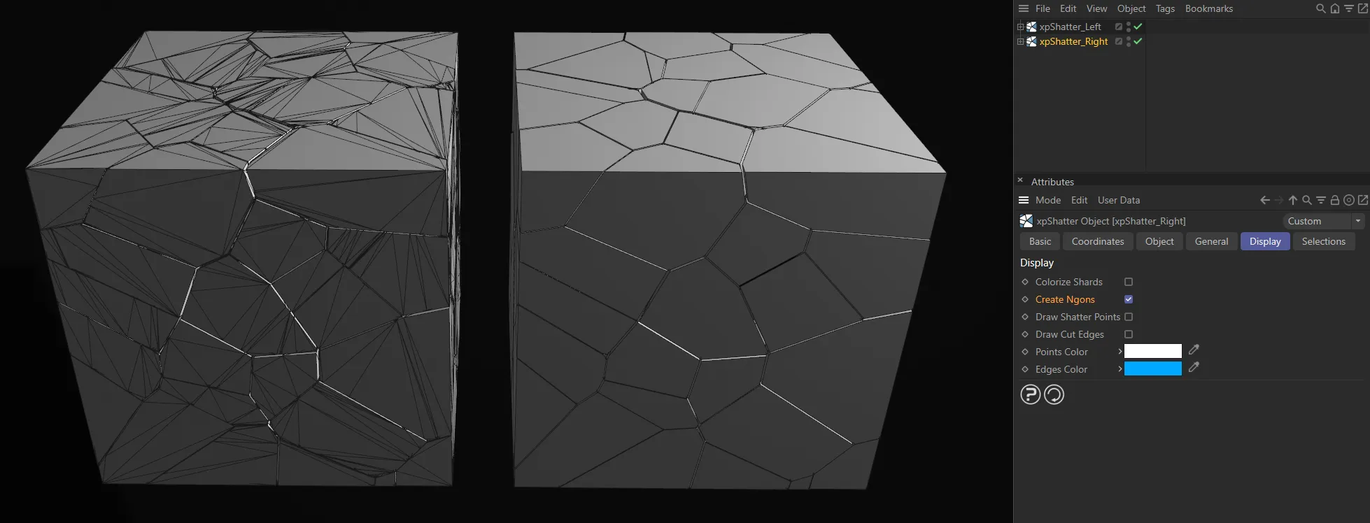
With Gouraud Shading (Lines) applied to the viewport, there are no Ngons on the left image. The right image has Create Ngons enabled.
Draw Shatter Points
Section titled “Draw Shatter Points”If enabled, this will draw the points which are used to generate the fragments in the viewport.
You can then see clearly how the object is shattered.
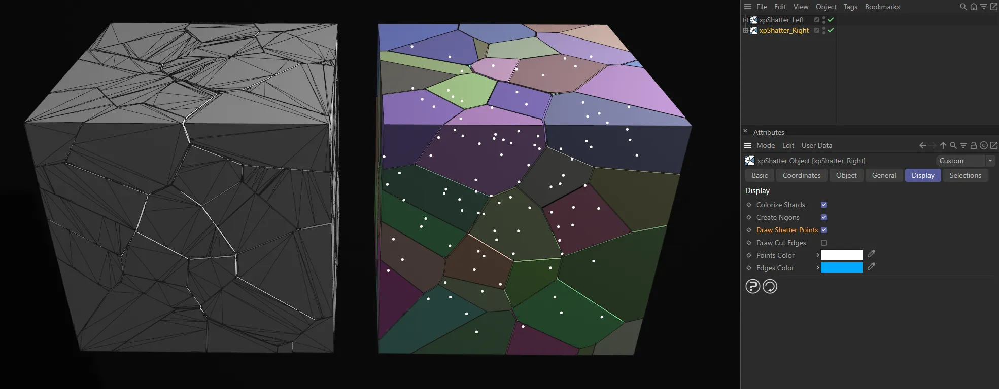
Draw Shatter Points is enabled in the right-hand image, displaying the points as white dots.
Draw Cut Edges
Section titled “Draw Cut Edges”If checked, the cut edges are drawn on the object to be shattered.
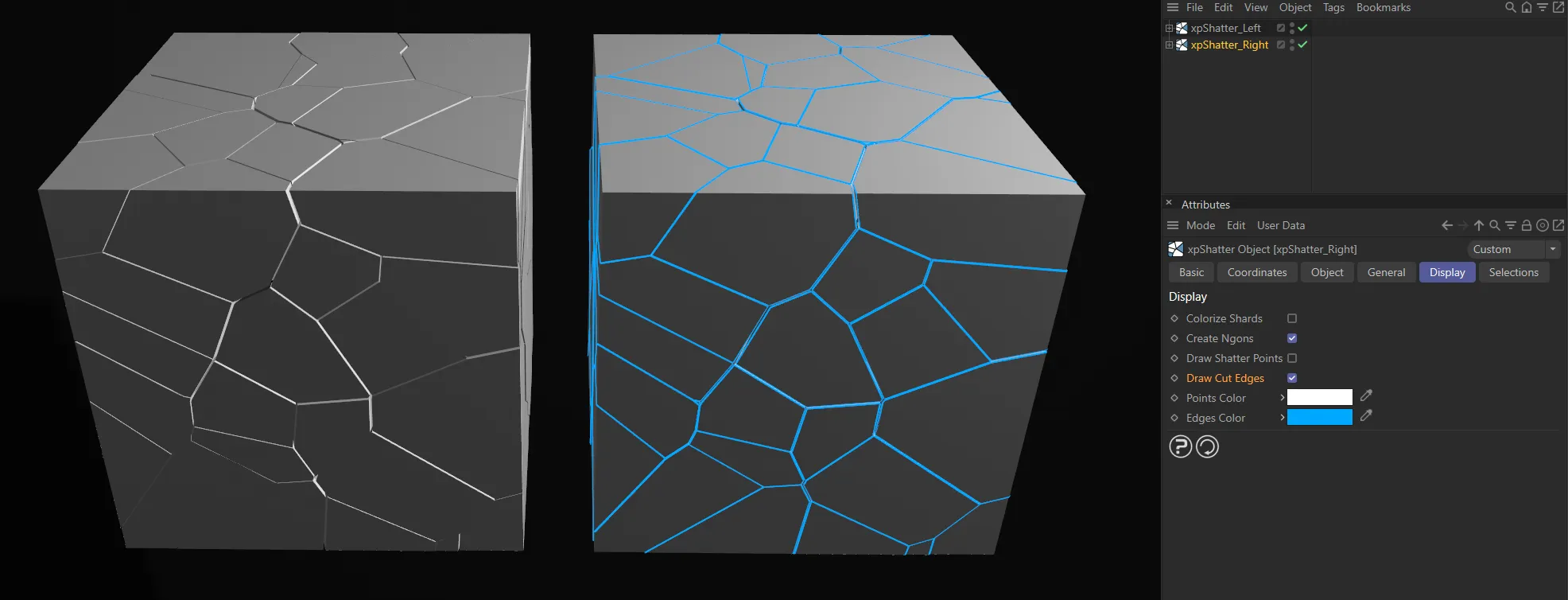
Draw Cut Edges enabled on the right, with Edges Color set as blue.
Points Color
Section titled “Points Color”The color of the shatter points, if Draw Shatter Points is enabled.
Edges Color
Section titled “Edges Color”The color of the cut edges, if Draw Cut Edges is checked.
Selection tab
Section titled “Selection tab”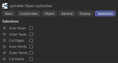
Selection tab menu.
Inner Faces
Section titled “Inner Faces”If enabled, adds a polygon selection tag containing the inner faces of each fragment.
You can use this to assign a material to the inner faces only.
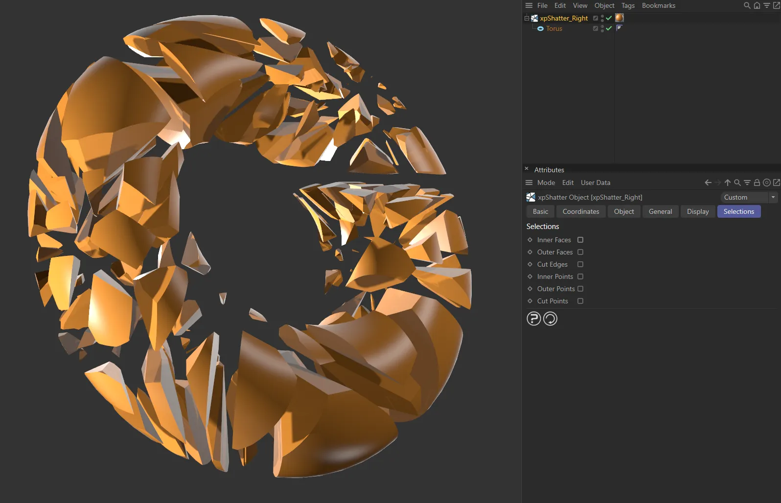
Inner Faces unticked (disabled).
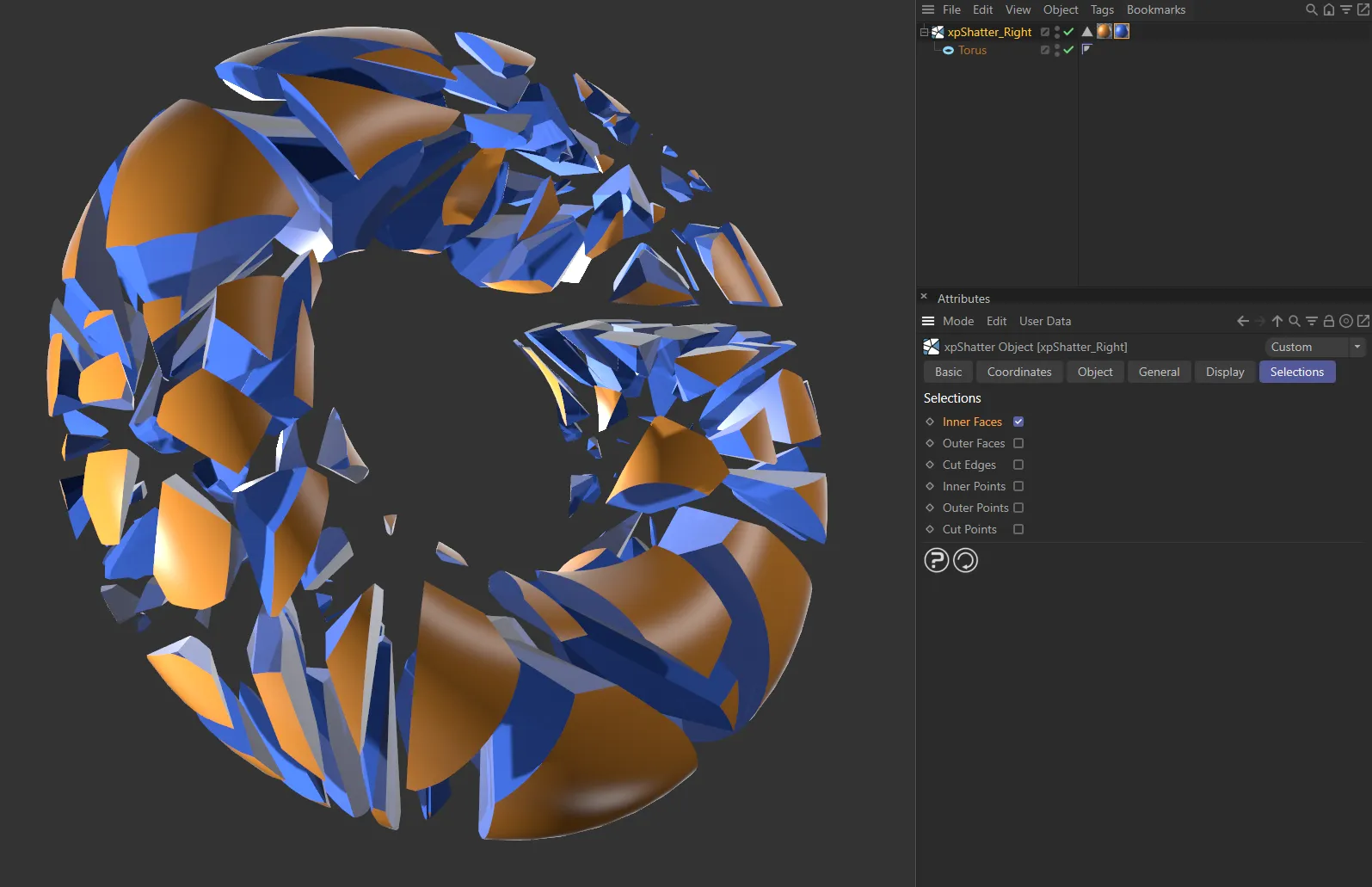
Here, with Inner Faces ticked and enabled, a blue material can be assigned to those inner faces.
Outer Faces
Section titled “Outer Faces”If enabled, adds a polygon selection tag containing the outer faces of each fragment.
You can use this to assign a material to the outer faces only.
Cut Edges
Section titled “Cut Edges”If enabled, adds an edge selection tag containing the newly-created cut edges of the fragments.
Inner Points
Section titled “Inner Points”These are points which are neither cut points nor outer points (all the points other than those which are in the cut and outer points selections).
Outer Points
Section titled “Outer Points”These are points which were present in the original mesh.
Cut Points
Section titled “Cut Points”These are the extra points created in order to make the cuts.
Copyright © 2026 INSYDIUM LTD. All rights reserved.