xpScatter
xpScatter enables you to scatter objects over another object using features such as texture, shaders, illumination and topology to determine where the objects are placed.
The objects to scatter must be made child objects of the xpScatter object.
General tab
Section titled “General tab”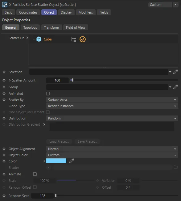
xpScatter General tab settings.
Scatter On
Section titled “Scatter On”The surfaces to be scattered with other objects.
This can be be any polygon object or a parametric object which, if made editable, would be a polygon object.
Splines are also supported.
If you untick the box next to the object name, nothing will be scattered onto that object until it is ticked again.
Selection
Section titled “Selection”This field is only visible if an object is present and selected in the Scatter On list.
You can drag a selection tag from the surface object into this link field and the objects will only be scattered onto the selected area.
The selection can be polygons, points, edges or a vertex map; internally, it will be converted into a polygon selection before use.
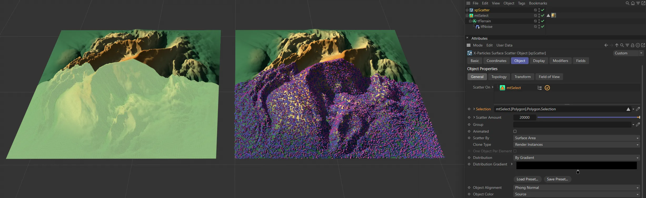
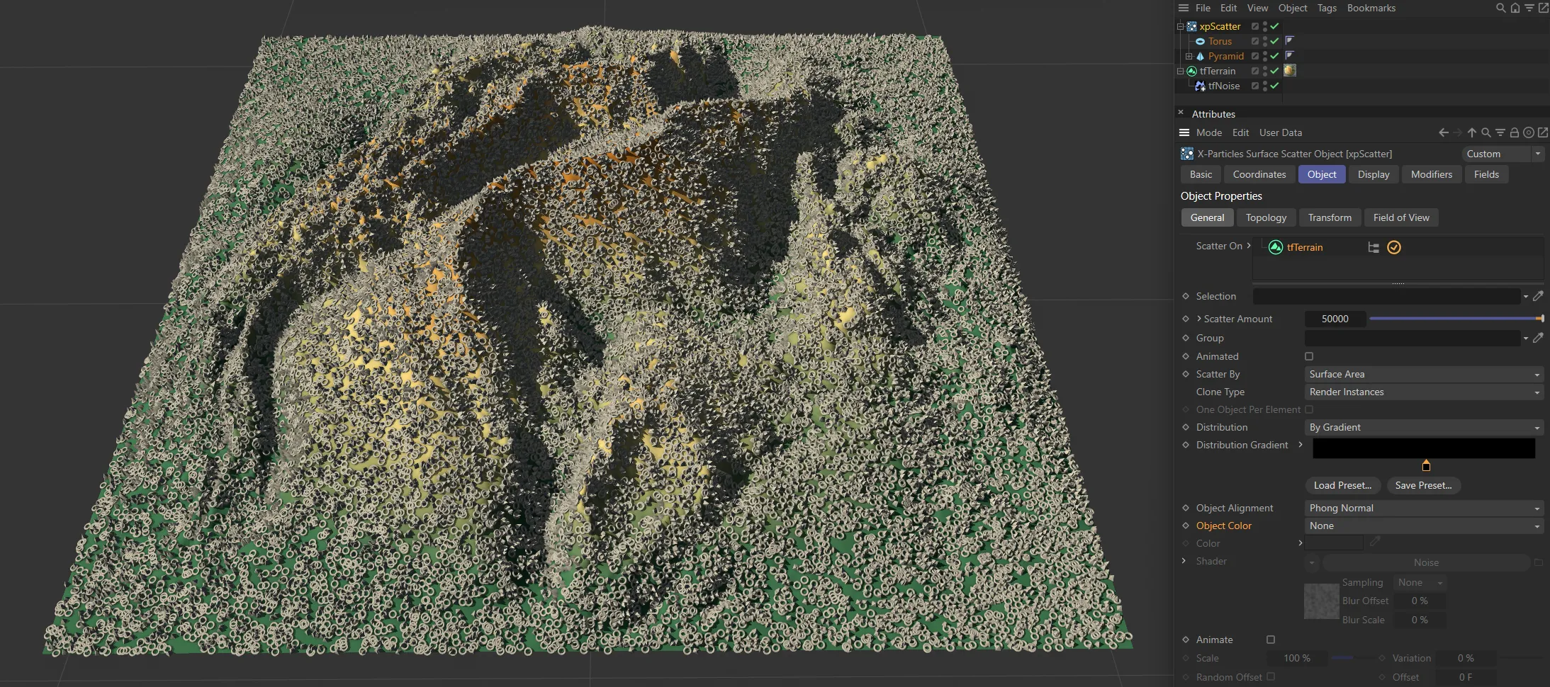
In this image, the base object (tfTerrain) has a selection tag which is linked in the xpScatter’s Selection field, restricting the areas on the terrain where scattering takes place.
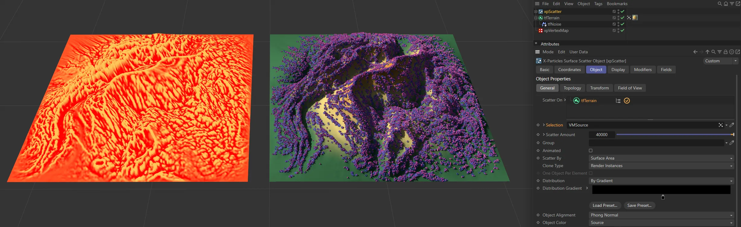
This scene uses a vertex map with a curvature layer (generated in xpVertexMap). Scattering is occurring in the areas in the vertex map with most weight.
Scatter Amount
Section titled “Scatter Amount”The number of objects to scatter on the surface.
If you click the little arrow next to the label, you will see the Render Count parameter.
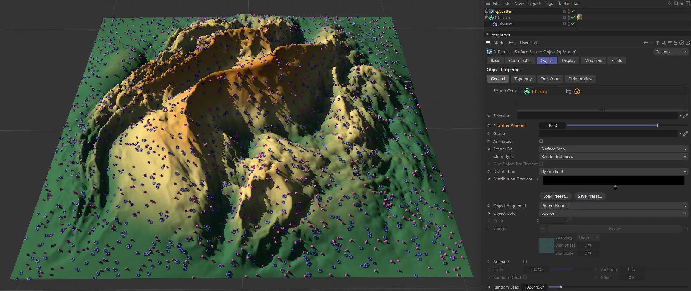
Scatter Amount set at 3000.
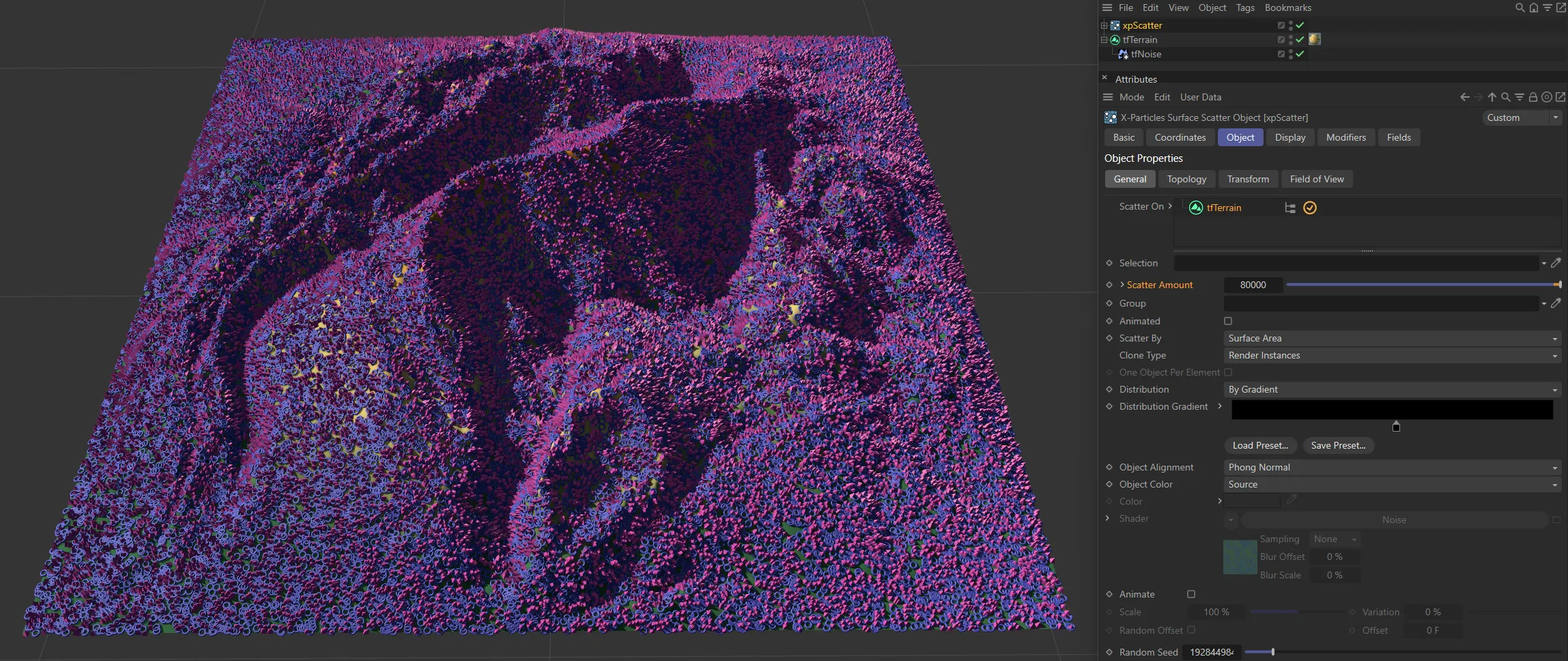
Scatter Amount raised to 80,000.
Render Count
Section titled “Render Count”This is the number of objects that will be generated when rendering to the picture viewer (not when rendering to the viewport).
By default, it is set to zero, which will generate the same number of objects as in Scatter Amount.
Any non-zero value will result in that number of objects being generated on rendering to the picture viewer.
You can drag a particle group into this field and the xpScatter object will use the parameters, such as color and scale, from this group.
Simply hit the ‘A’ key on the keyboard to do this, or switch to a different tab in the xpScatter object’s interface.
When using a group, you need to remember to set the speed in the group to zero; if you don’t, the objects will be offset from the surface by the distance a particle would travel in one frame.
Animated
Section titled “Animated”This setting updates the cloned objects every frame. This enables both the use of animated source objects, and X-Particles modifiers, to animate the generated clones.
In this scene, Animated is enabled, and the xpScale modifier is able to apply scaling animation to the scattered objects.
Scatter By
Section titled “Scatter By”Set as Surface Area, by default, this is the primary method to determine how the objects are scattered over the surface.
The alternative settings are: Polygons, Surface Texture, Surface Illumination, Polygon Center, Vertices, Edges and Object Volume.
Polygons
Section titled “Polygons”Objects are scattered over the polygons of the Scatter On objects.
The polygons are not weighted by size - all polygons have an equal chance of receiving scattered objects.
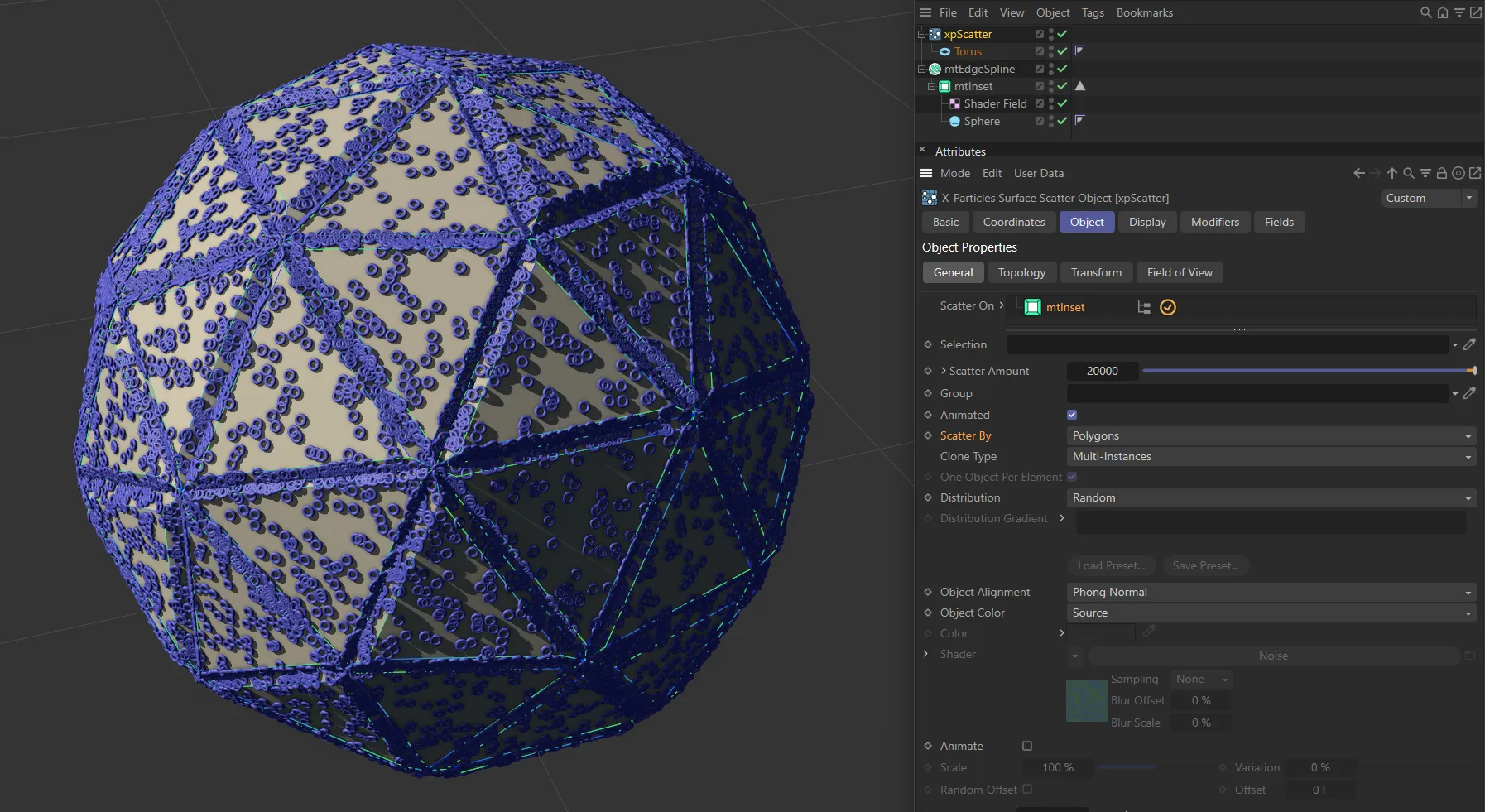
Scatter By set to Polygons.
Surface Area
Section titled “Surface Area”This is the same as for polygons, but account is taken of the relative sizes of the polygons, so larger polygons receive more scattered objects.
This can result in a more even distribution of objects.
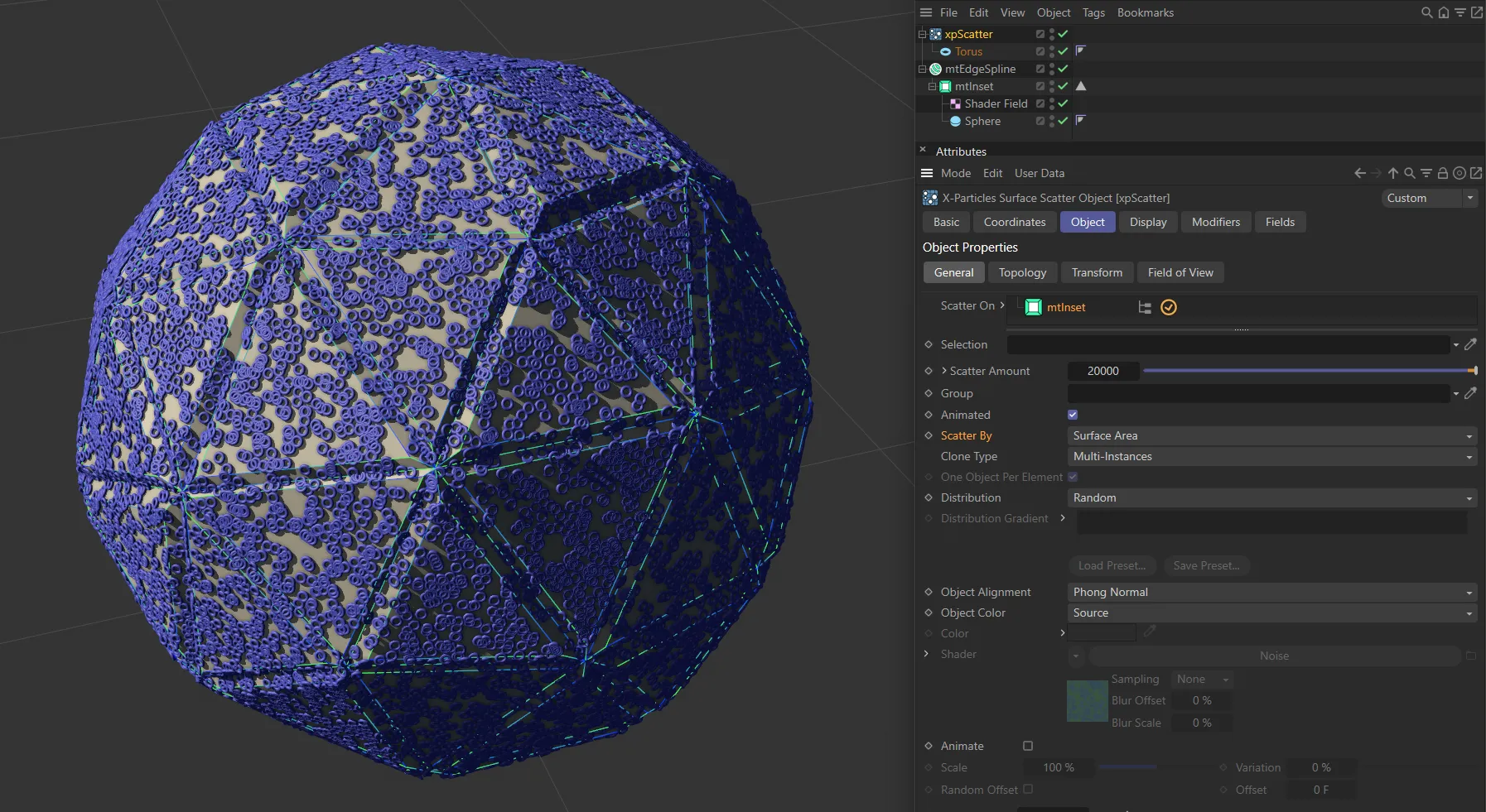
Scatter By set to Surface Area.
Surface Texture
Section titled “Surface Texture”With this option, the area to be covered is controlled by a texture or shader.
If you select this option, the following four parameters (a subset of those available in the emitter, if you control emission by texture) become available.
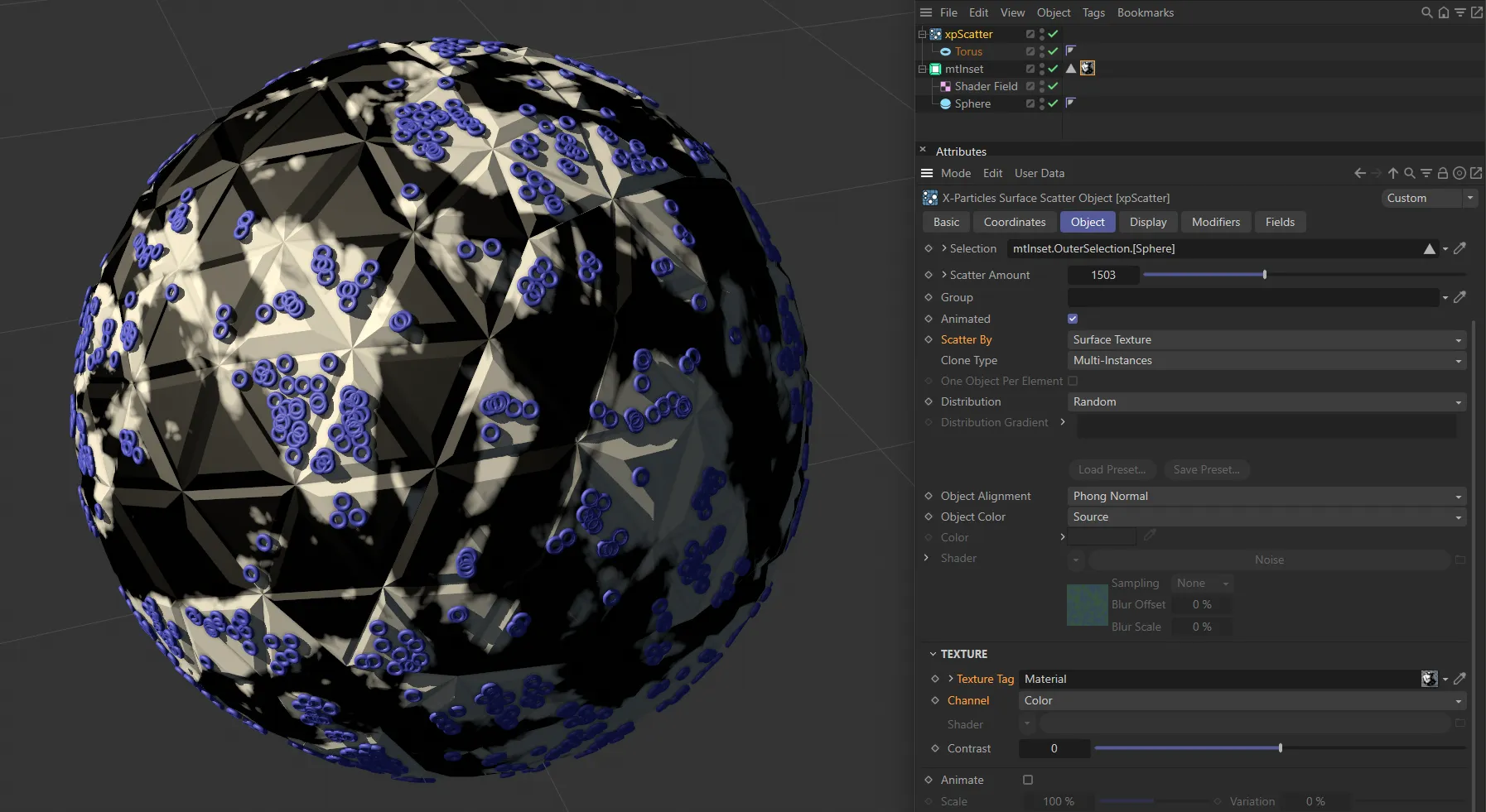
Scatter By set to Surface Texture.
Texture Tag
Section titled “Texture Tag”You can drag a texture tag into this field and the emitter within the xpScatter object will use the material referenced by that tag.
Any of the texture tags assigned to the surface object may be used.
Any projection mapping can be used in the tag except Frontal or Camera mapping.
Using a tag is convenient if you have already set up a material and don’t want to have to duplicate it in another shader.
Once you add the tag to this field, you can select the channel to sample in the Channel drop-down menu, but you can no longer use the Shader field (a texture tag and a shader can not be used simultaneously).
Channel
Section titled “Channel”This is the material channel which governs the generation of the objects to be scattered.
If you have dragged a texture tag into the Texture Tag field, you can choose the channel to use from the material.
By default this is the Color channel, but you can choose from several others.
One thing you can do is use a channel which is not being used in the material.
For example, you could set up a shader to govern object placing in the displacement channel but leave that turned off in the material editor.
The emitter can still sample that channel even though it is not being used in the material.
Shader
Section titled “Shader”Instead of using an existing texture tag, you can set up any shader in exactly the same way as if you were using the material editor.
Alternatively, you can copy a channel from a material and paste it into this field.
If you set up a shader, then add a texture tag, only the tag is used; the shader will be ignored.
Contrast
Section titled “Contrast”The scattering of objects is controlled by the overall color brightness of the sampled texture or shader; the brighter the color, the more objects are generated.
If you find that more objects are being scattered in darker areas than you would like, you can increase the Contrast setting to reduce the number in dark areas.
Conversely, turning down the contrast below zero will increase the number of objects in darker areas.
Surface Illumination
Section titled “Surface Illumination”With this option, the area to be covered is controlled by the light shining on the surface.
If you select this option, the following three parameters (a subset of those available in the emitter if you control emission by illumination) become available.
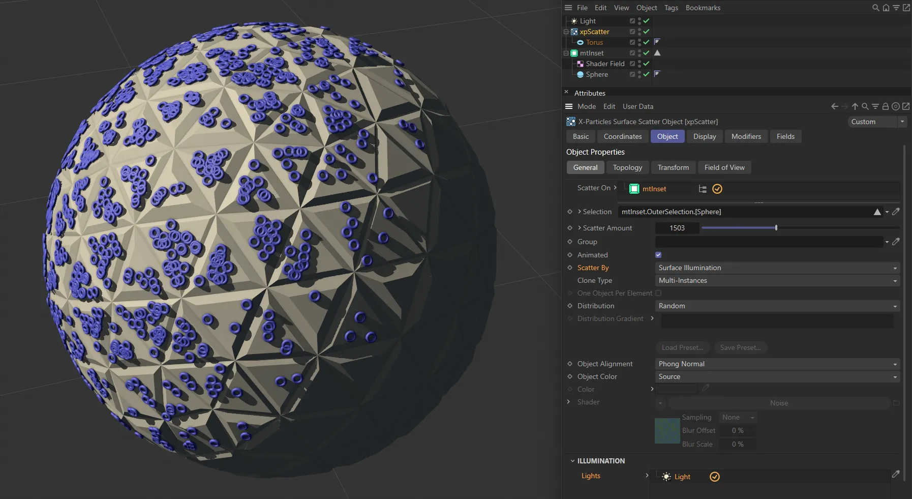
Here, Scatter By is set to Surface Illumination.
Lights
Section titled “Lights”Drag the lights you want to control object scattering into this list.
If there are no lights in the list, no objects will be scattered on the surface.
Max Samples
Section titled “Max Samples”If you use a spotlight, the emitter will sample the surface of the object in an attempt to find an area which is illuminated.
If the spot is very small, this may take a long time, so this setting controls how many samples are taken before the emitter assumes that the object is not illuminated.
Increase this value if you use a small spot and don’t get many objects being scattered.
Brightness Threshold
Section titled “Brightness Threshold”The angle of incidence of the light rays striking the object surface is compared to this setting.
The threshold value must be exceeded for any objects to be generated, so the higher this setting, the fewer objects are scattered.
If the light rays strike the surface at just under a right angle to the normal, you will need to set this value very low as otherwise it is likely that no objects will be generated.
But if the light rays are almost parallel to the surface normal, this setting will have no effect unless set very high.
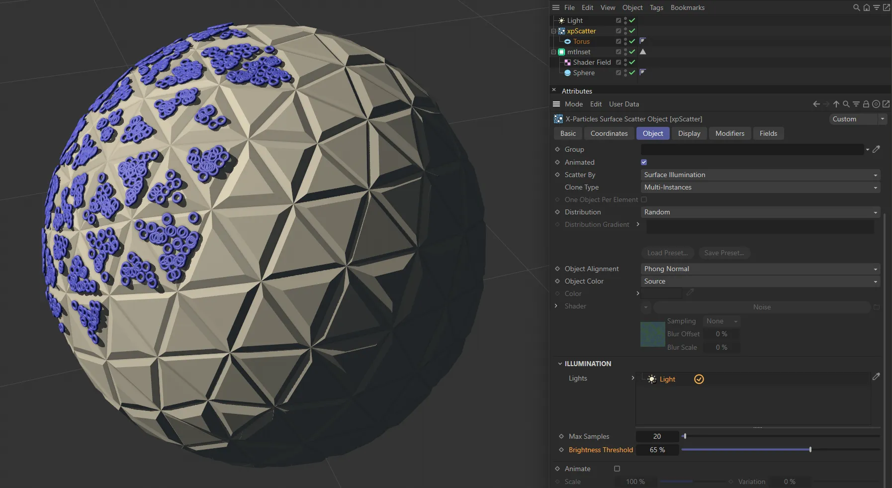
With Scatter By set to Surface Illumination, this image shows a Brightness Threshold of 65%.
Polygon Center
Section titled “Polygon Center”Objects are scattered on the center of polygons.
With this setting, the parameter One Object Per Element becomes available and, if that is enabled, one object will be generated at the center of each polygon.
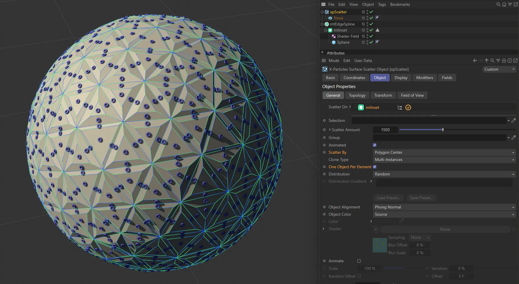
Scatter By set to Polygon Center.
Vertices
Section titled “Vertices”Objects are scattered on the vertices of the Scatter On objects.
With this setting, the parameter One Object Per Element becomes available and, if that is enabled, one object will be generated at each vertex.
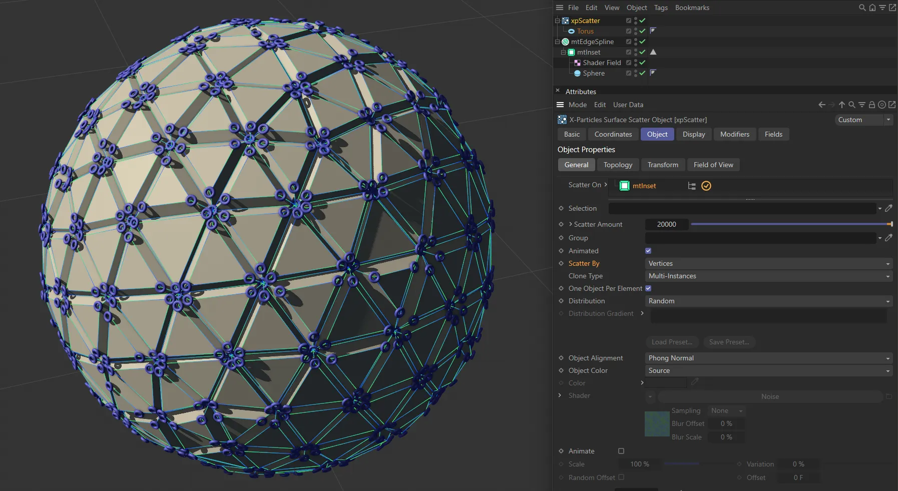
Scatter By set to Vertices.
Objects are scattered on polygon edges.
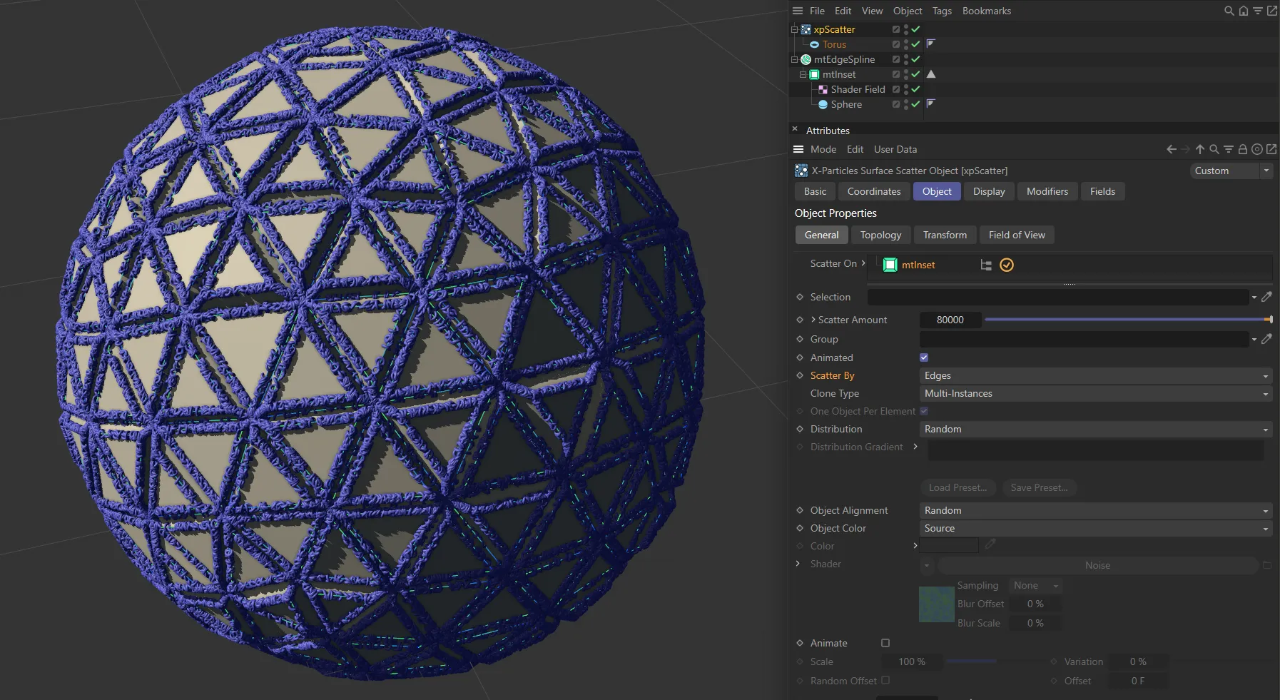
Scatter By set to Edges.
Object Volume
Section titled “Object Volume”Objects are generated inside the Scatter On objects.
The best results are obtained using objects with closed volumes such as a sphere, pyramid, etc.
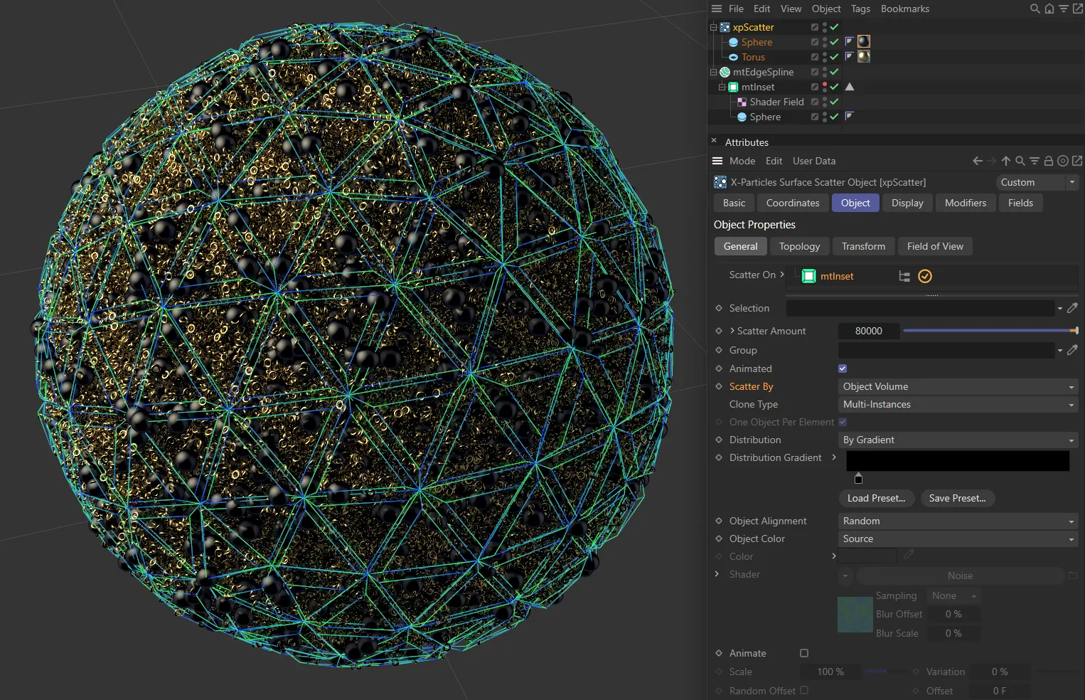
In this image, Scatter By is set to Object Volume, with a Sphere and a Torus used.
Clone Type
Section titled “Clone Type”Set as Render Instances, by default, this menu lets you choose how the clones of the objects to be scattered are generated.
Duplicate generates full copies, as if you duplicated the object in the object manager.
Instances generates Cinema 4D instances, while Render Instances generates render instances.
Multi Instances are the most efficient clone type.
Further details of instances, render instances and multi instances can be found in the Cinema 4D documentation.
One Object Per Element
Section titled “One Object Per Element”This setting is only available if Scatter By is set to Polygon Center or Vertices.
If enabled, one object will be generated at the center of each polygon (or at each vertex).
Distribution
Section titled “Distribution”Set as Random, by default, the objects to be scattered are chosen randomly.
In practice, this results in an equal distribution of the various objects.
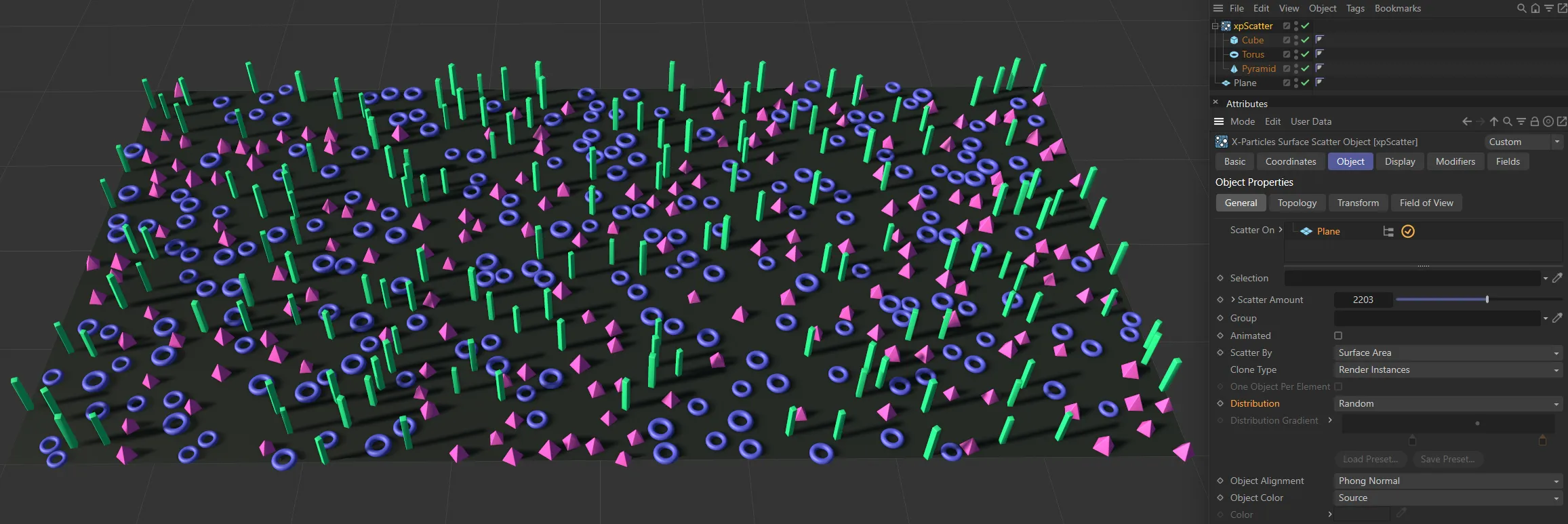
Distribution set to Random.
The alternative setting is By Gradient: with this option, you use a gradient to determine the relative proportion of the objects.
This is the Distribution Gradient (see below).
Distribution Gradient
Section titled “Distribution Gradient”This gradient is only available if you set Distribution to By Gradient.
Using this gradient is not difficult but the first thing to remember is that the colors are completely irrelevant - you can use any colors you like, it makes no difference.
The critical thing is the position of the gradient knots.
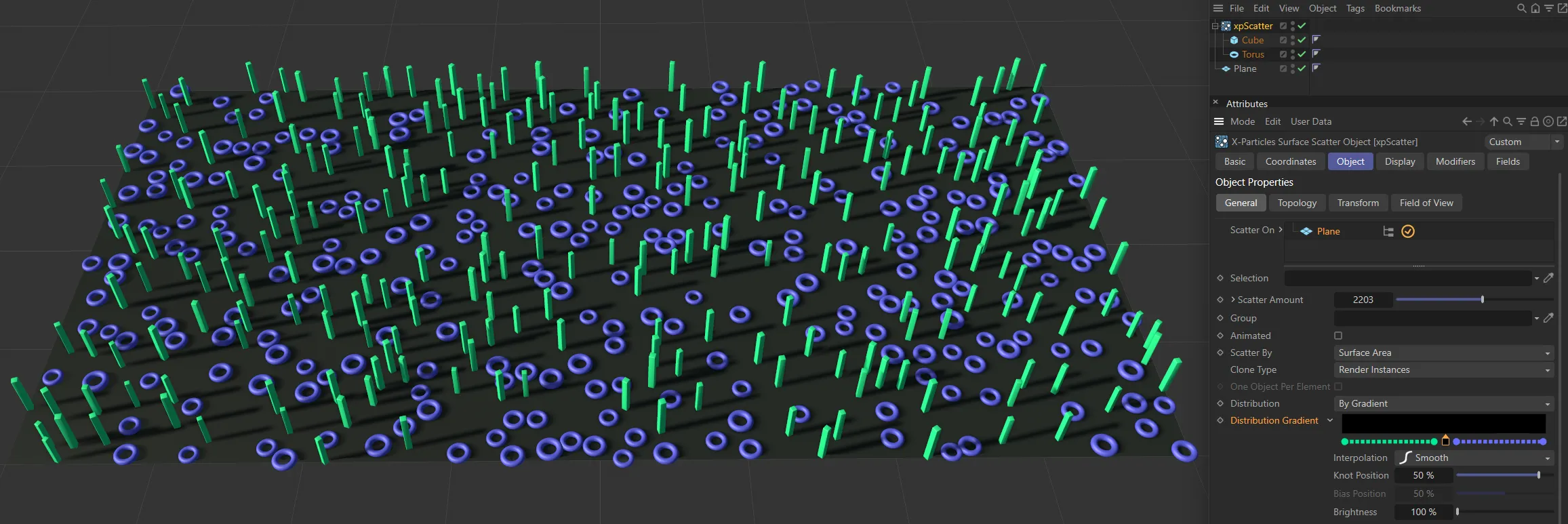
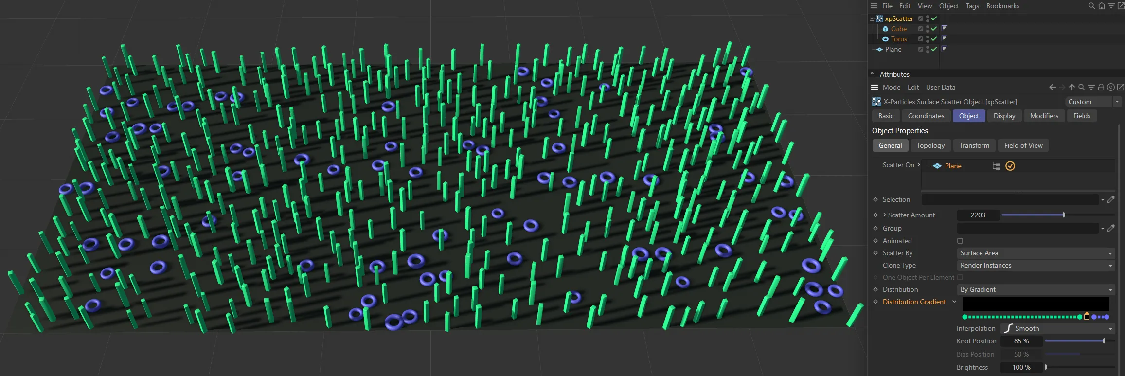
In this image, Distribution is set to By Gradient. The gradient knot is at 50%, with two scattered source objects giving a balanced scattering; there are equal amounts of Cubes and Torus objects.
In this second example, the knot position is at 85% so the Torus is only 15% of the scattered objects.
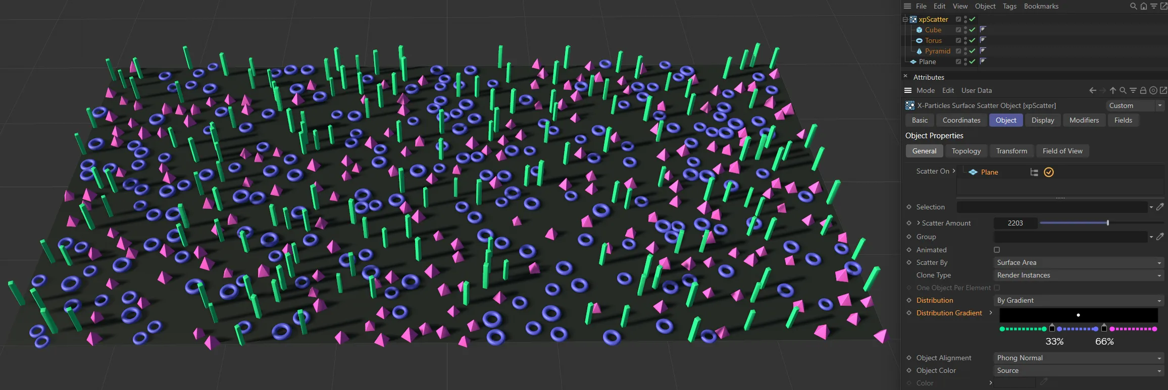
Here, there are three source objects. With the two knots set at 33% and 66%, this gives an equal balance.
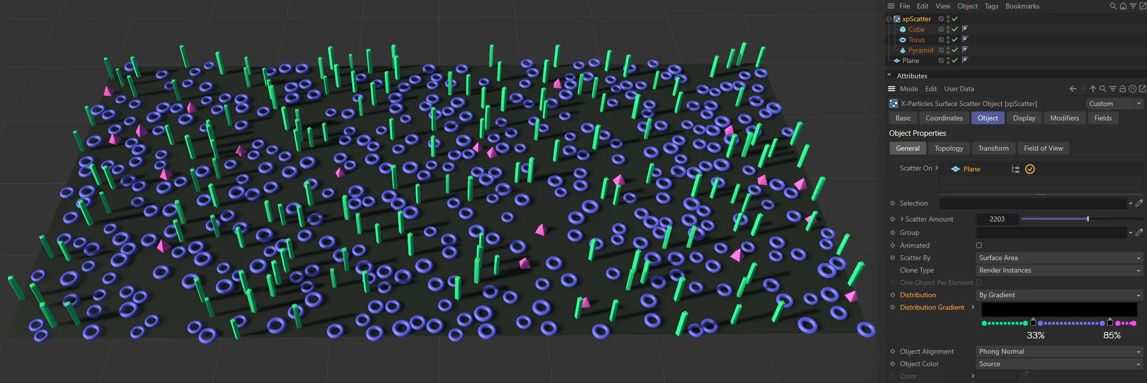
In this final image, the second knot is at 85%, scattering more Torus objects and less pyramids than before.
Object Alignment
Section titled “Object Alignment”Set as Normal, by default, this is the alignment of the scattered objects along a particular axis.
Much of the time, you will want the alignment to be along the normal of the surface where the object is generated, so this is the default setting.
That won’t always be the case.
Trees, for example, might be expected to grow straight up even if the surface on which they stand is not horizontal.
With this menu, you can select the direction in which the object is aligned.
The other options are: X+ Axis, X- Axis, Y+ Axis, Y-Axis, Z+ Axis, Z- Axis, Phong Normal and Random.
Object Alignment set to Phong Normal.
Object Alignment set to Random.
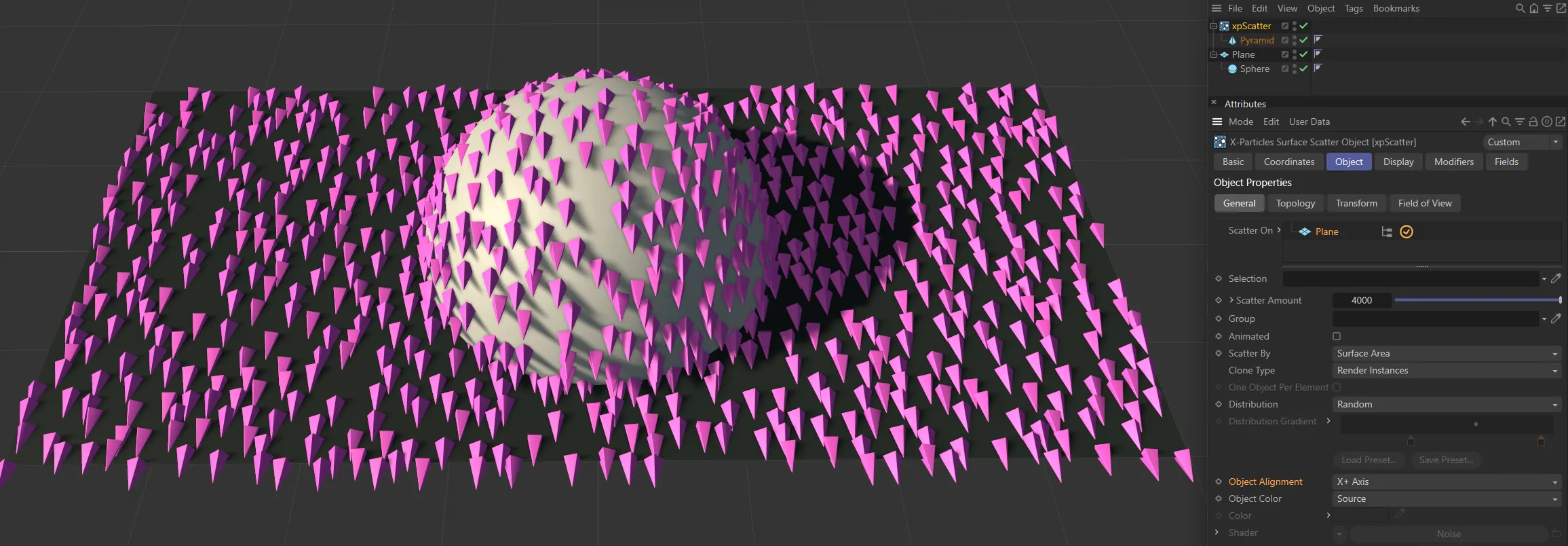
Object Alignment set to X+.
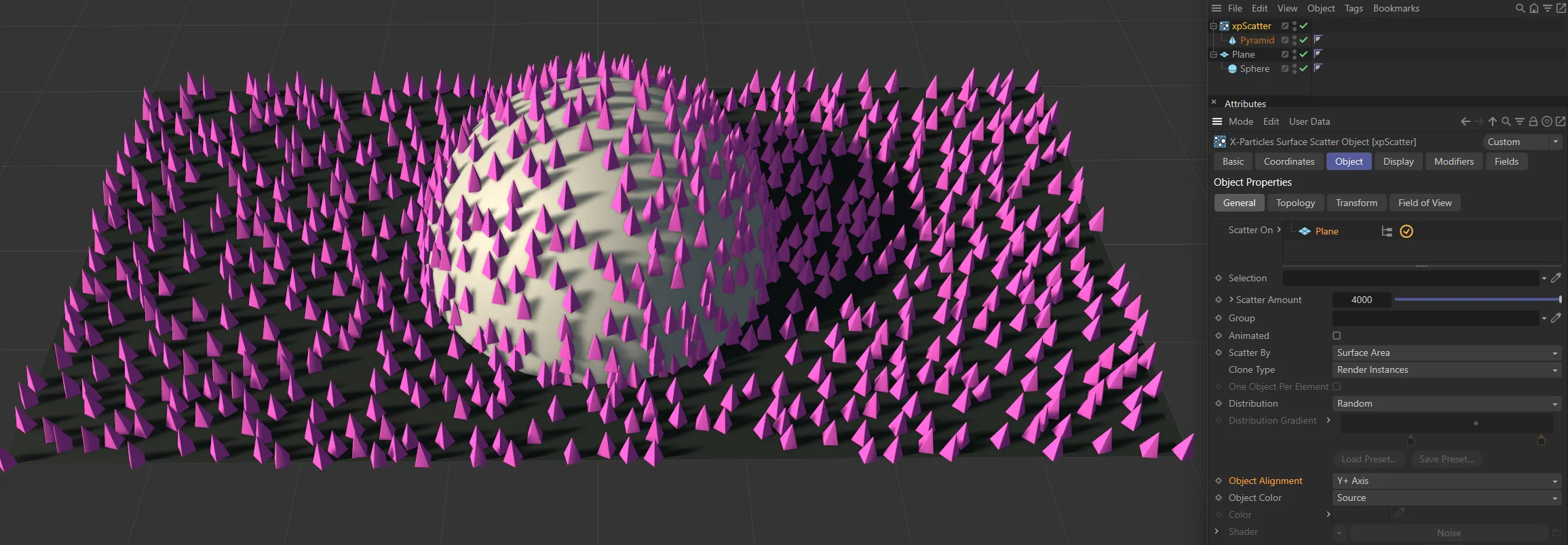
And, finally, Object Alignment set to Y+.
Object Color
Section titled “Object Color”Set as Custom, by default, you can set the color of the scattered objects with this menu.
This only applies if the scattered objects do not have a material applied to them; if they do, the material takes precedence.
The other options are: None, Shader and Source.
No color is set.
With Object Color set to None, all scattered objects are the default gray.
Shader
Section titled “Shader”The color is obtained from a shader in the Shader link field.
With Object Color set to Shader, the color is obtained from a shader in the Shader link field.
Source
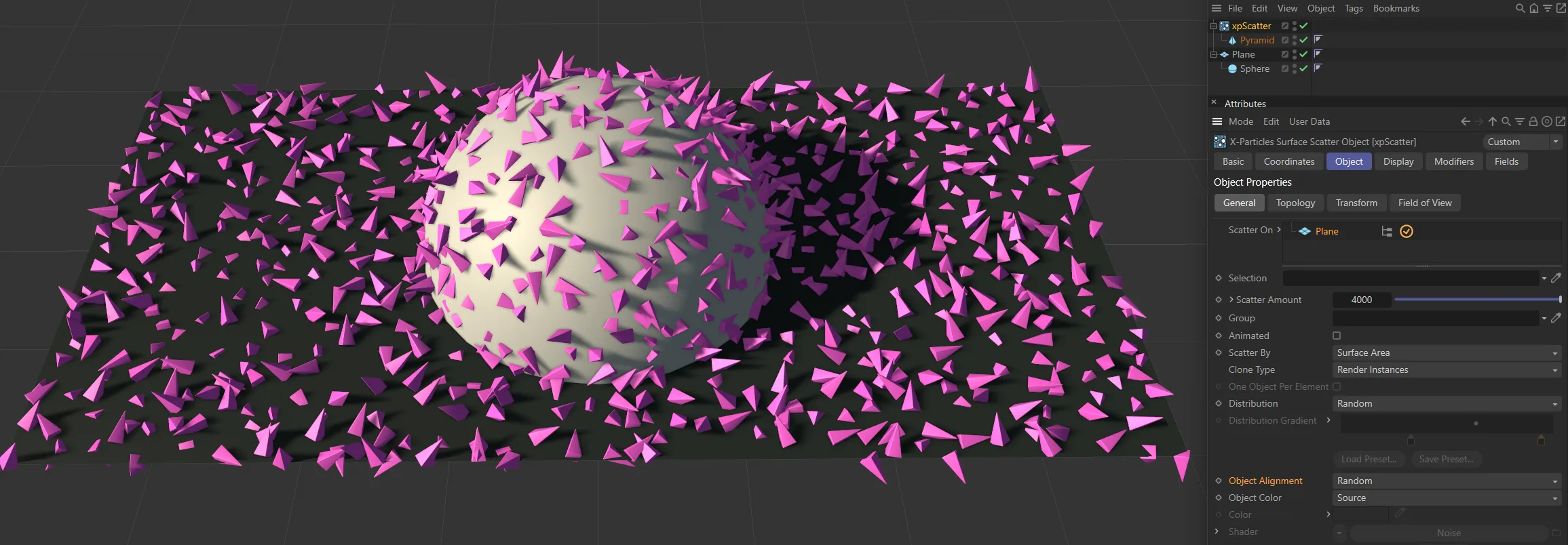
Section titled “Source”The color of the generated objects is the source object’s base color.
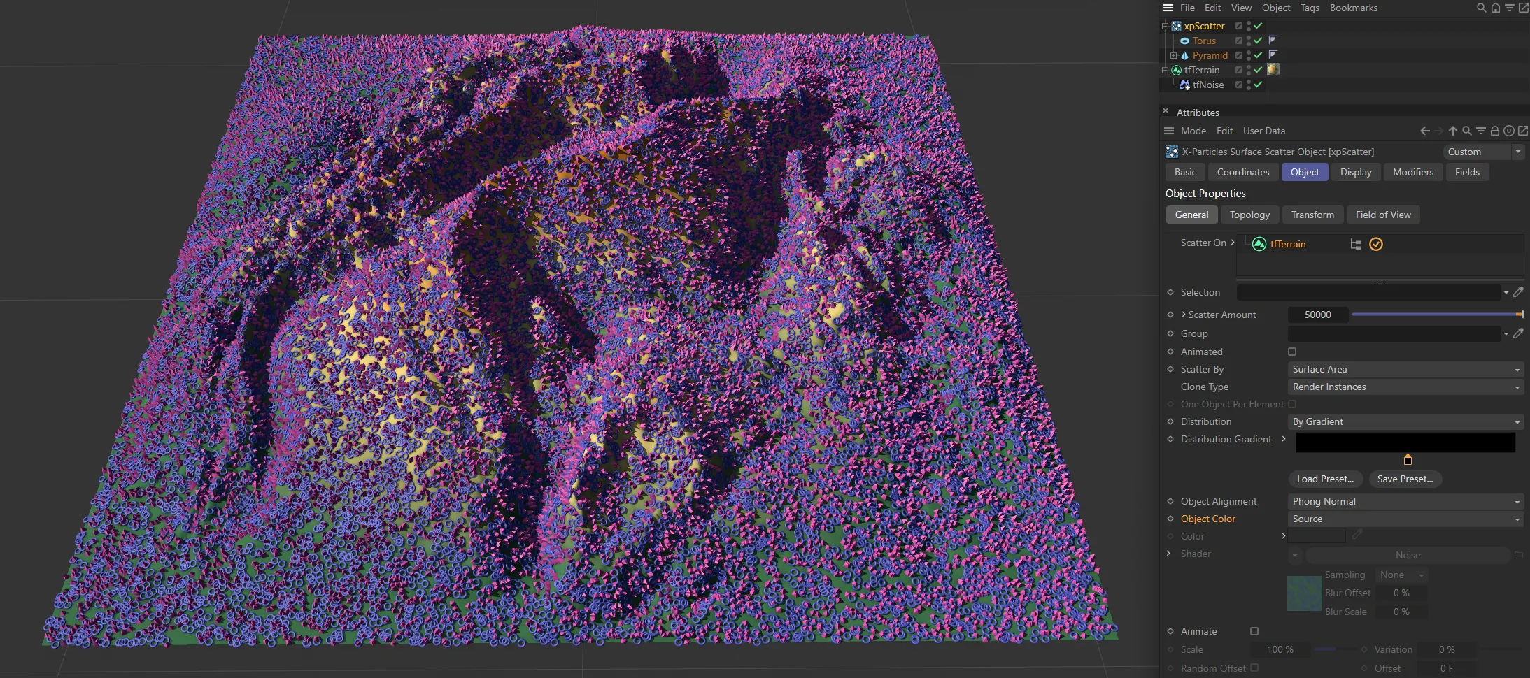
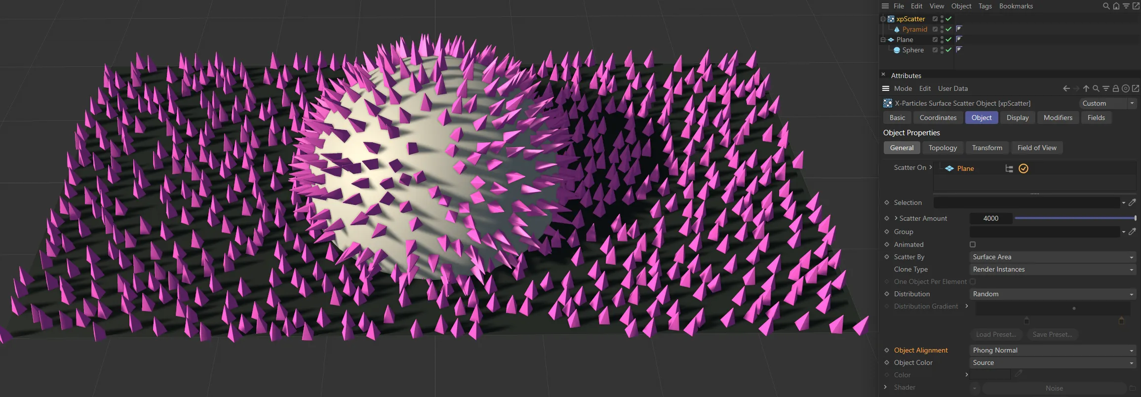
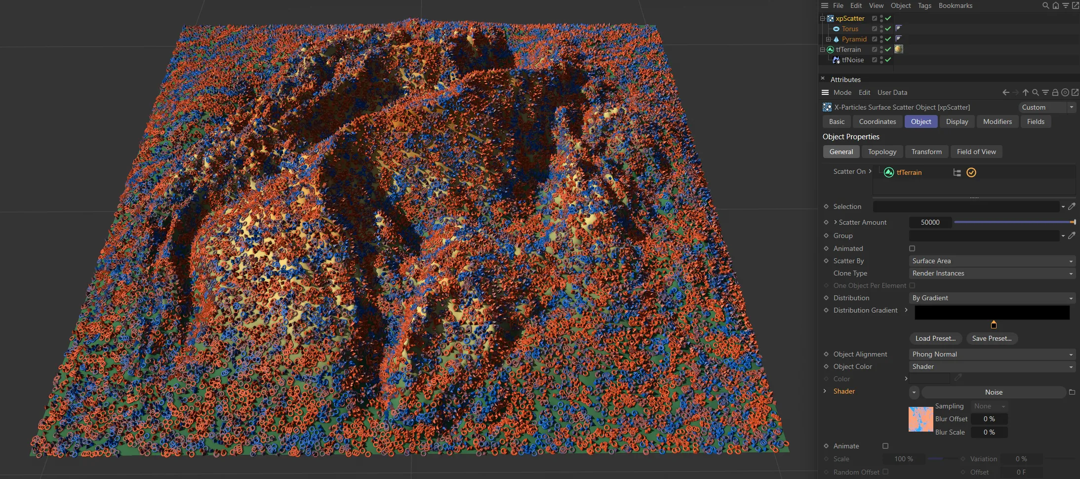
Here, Object Color is set to Source. The scattered objects are the same color as their source objects, with Pyramids being pink and Torus purple.
Custom
Section titled “Custom”The color is obtained from the Color field.
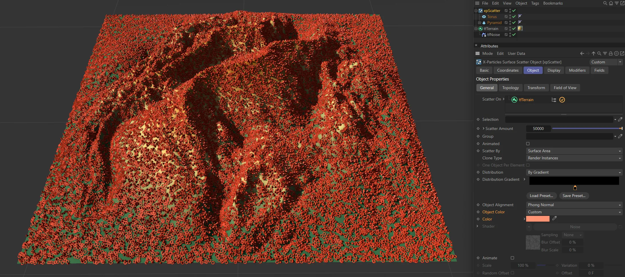
In this scene, with Object Color set to Custom, the scattered objects are all orange, as set by the custom Color selection.
The color of the generated objects when Object Color is set to Custom.
Shader
Section titled “Shader”The color of the generated objects when Object Color is set to Shader.
Add a shader of your choice to this field.
Animate
Section titled “Animate”These settings enable the adjustment of a source object’s animation. They can be used to generate variation in the animation of clones.
Keyframed PLA (Point Level Animation) of the xpScatter’s source object(s) will only be seen if Animate is enabled.
Clone Type must be set to Duplicate and Animated must also be enabled in order for this to work.
In this animation, with Animate enabled, the PLA (Point Level Animation) seen in the source object, on the right, is also seen in the scattered clones. The source object has been keyframed so that the points ‘grow’ over 50 frames. This effect can be seen in each of the clones.
Scale, Variation
Section titled “Scale, Variation”The Scale value determines how fast the object will be animated.
For example, if you have an animated bird flapping its wings, a scale of 200% will cause the wings to flap twice as fast as normal.
If you add some variation, the objects will be animated at different speeds.
Random Offset, Offset
Section titled “Random Offset, Offset”By default, all animated objects will be animated from the same point in the scene.
What this means is that all objects will appear to have the same animation - so birds will all flap their wings in unison, for example.
You can adjust the starting point by altering the Offset value.
Often, however, you will want the objects to be animated from different starting points from each other, which gives a more natural effect.
To do this, enable the Random Offset setting.
Random Seed
Section titled “Random Seed”A random seed value used to select objects and their position on the surface.
Topology tab
Section titled “Topology tab”
xpScatter Topology tab settings.
Topology Space
Section titled “Topology Space”Set as Local, by default.
The alternative is World.
The position of the generated object is relative to the surface object (to be precise, to its axis).
This means that moving or rotating the object will not affect the height or slope of any polygon, since they remain the same, relative to the axis.
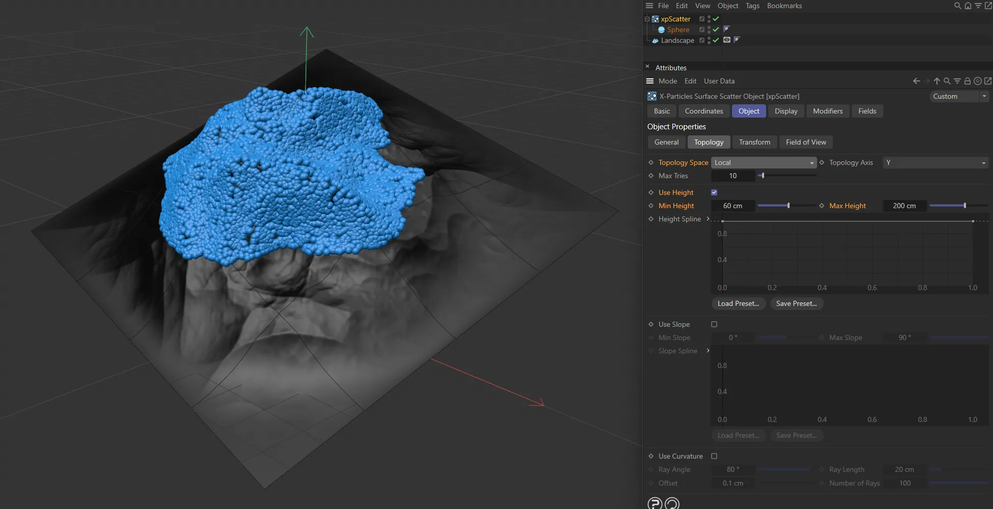
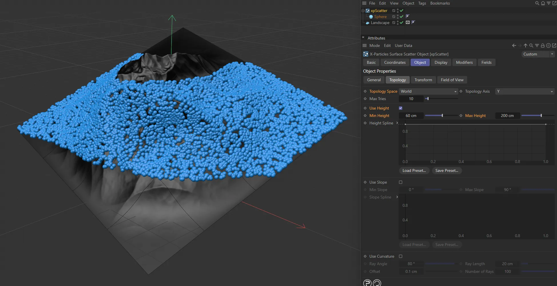
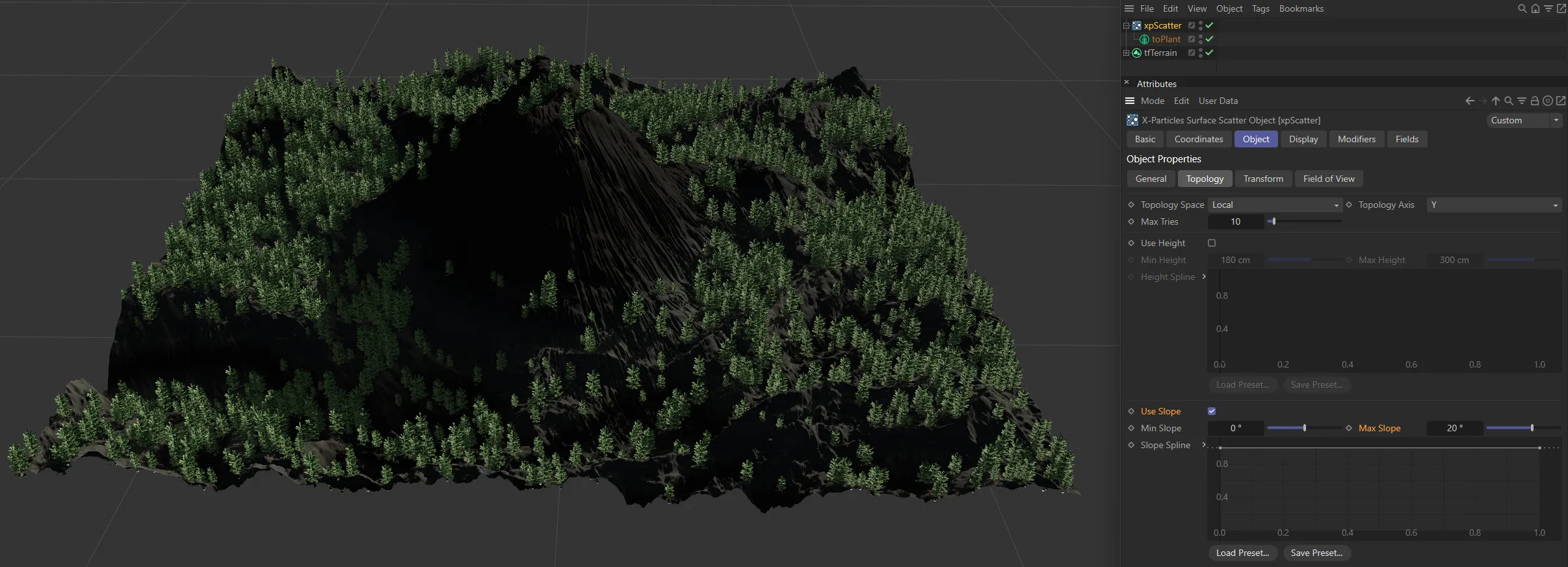
Here, Topology Space is set to Local so the Min Height and Max Height settings are being applied in local space, scattering objects only at the peak of the landscape, even though it is rotated.
With this option, the height and slope of any polygon is relative to the 3D world axis.
Moving or rotating the surface object may then have a significant effect on the polygons used for scattering objects.
With Topology Space set to World, the scattered objects are now ignoring the local base object’s space and are only being scattered within the height boundaries set within world space.
Topology Axis
Section titled “Topology Axis”The height and slope are assessed relative to either the X, Y, or Z axes.
By default this is the Y axis.
Max Tries
Section titled “Max Tries”Depending on the object and other factors, it may be very difficult, or impossible, to find a suitable point to add an object.
To prevent Cinema 4D from hanging, due to a calculation that never ends, xpScatter will only try to find a suitable point for the number of times given in this setting.
If you find that the number of objects being scattered is very small, you can increase this value but this will slow down the process.
Use Height
Section titled “Use Height”Check this box to enable height control of object scattering.
Min Height, Max Height
Section titled “Min Height, Max Height”The point where an object is generated must fall within the height range given by these two settings.
No objects will be generated on points outside of this range.
Remember that these settings are relative to the object axis when Topology Space is set to Local but to the world axis when it is set to World.
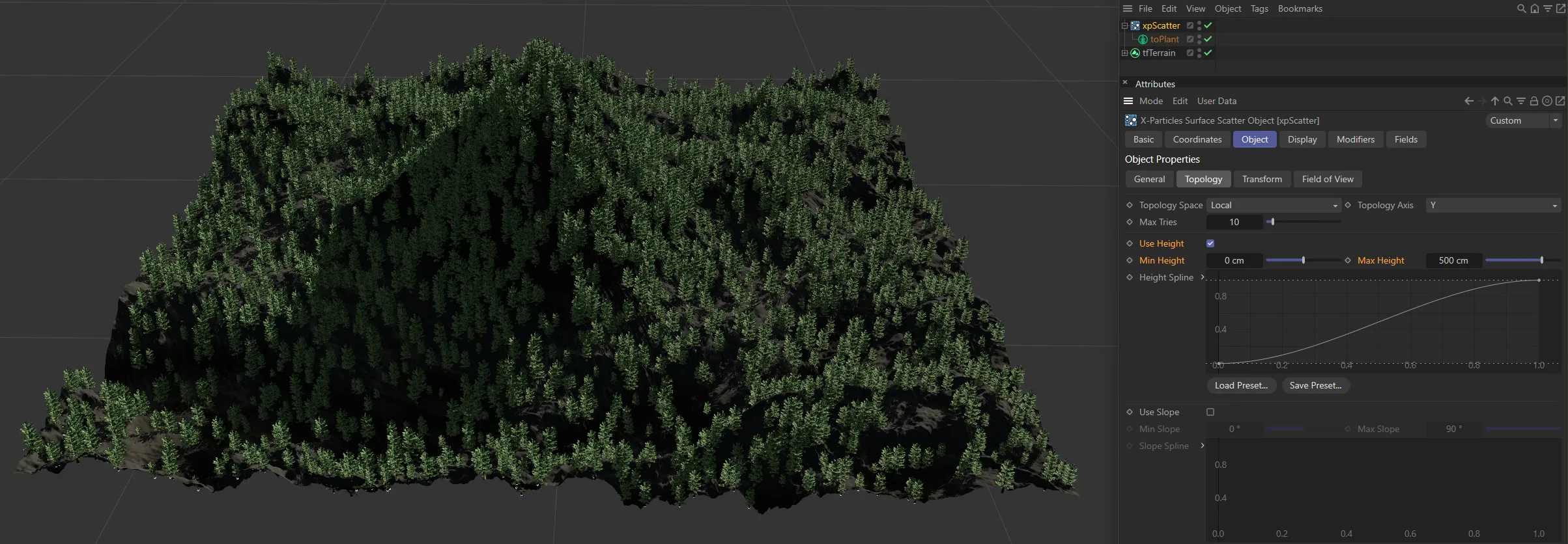
In this image, the default Min Height and Max Height settings, together with the base object’s mesh settings, mean that there are no restrictions on scattering.
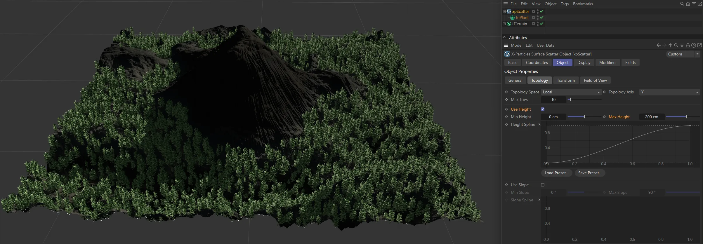
In this second image, the Max Height is set to 200cm, so objects cannot be scattered above that height.
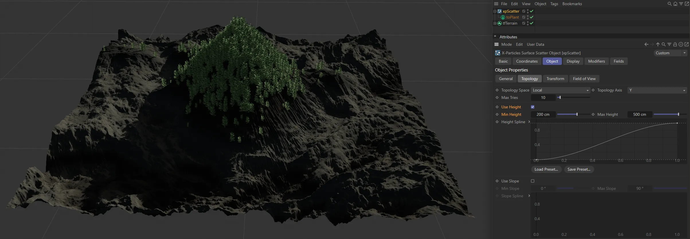
Now, the Min Height is set at 200cm and the Max Height has been increased to 500cm, restricting scattering of objects to the area between those two altitudes.
Height Spline
Section titled “Height Spline”By default the use of height-based control will result in a hard boundary between the area where objects are scattered and those where they are not.
You can use this spline to feather the edges of the scatter area, or use it to control the pattern of objects within the area (e.g. you could change the spline to give stripes where objects are placed alternating with stripes of no objects).
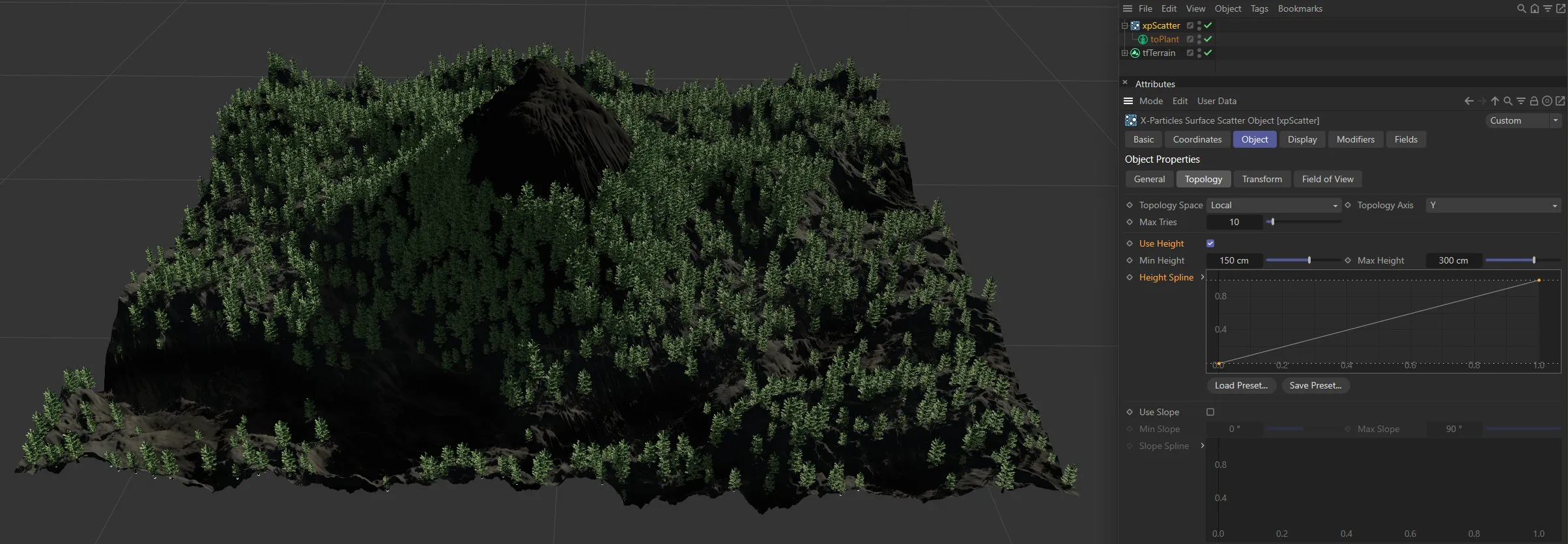
In this image, with the Min Height and Max Height settings restricting scattering between 150 and 300cm, the linear Height Spline setting is giving a linear blend between the areas with and without restrictions.
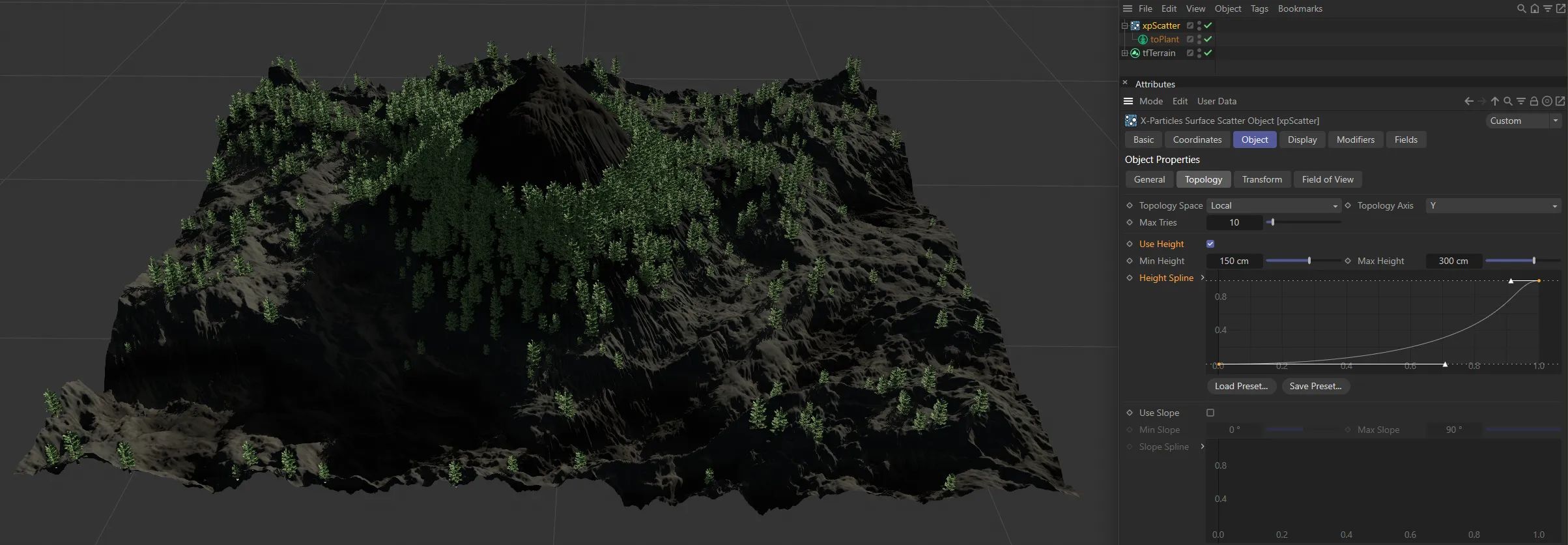
In this second image, using the same height restrictions, the custom Height Spline set gives a more gentle, feathered increase in the scattered objects.
Use Slope
Section titled “Use Slope”Check this box to enable slope control of object scattering.
Min Slope, Max Slope
Section titled “Min Slope, Max Slope”The point where an object is generated must fall within the slope range given by these two settings.
No objects will be generated on points outside of this range.
Remember that these settings are relative to the object axis when Topology Space is set to Local but to the world axis when it is set to World.
This occurs when the normal of the polygon used for scattering is parallel to the selected axis.
The maximum slope is either +90 or -90 degrees and these are reached when the polygon normal is at right angles to the selected axis.
Not all objects can have negative slopes; a Sphere does - these are the polygons on the ‘underside’ of the Sphere, but a Landscape object does not - all its polygons have a slope of zero degrees or greater.
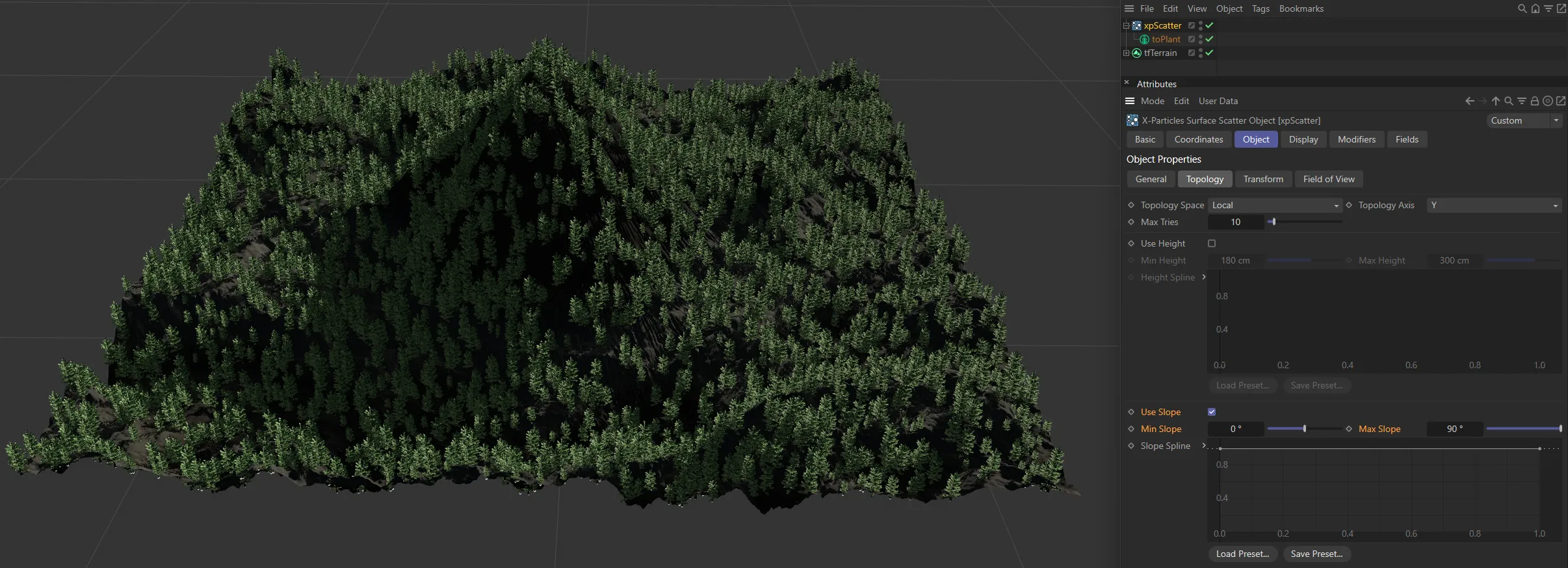
With Min Slope at 0 (zero) degrees and Max Slope at 90 degrees, there is no restriction.
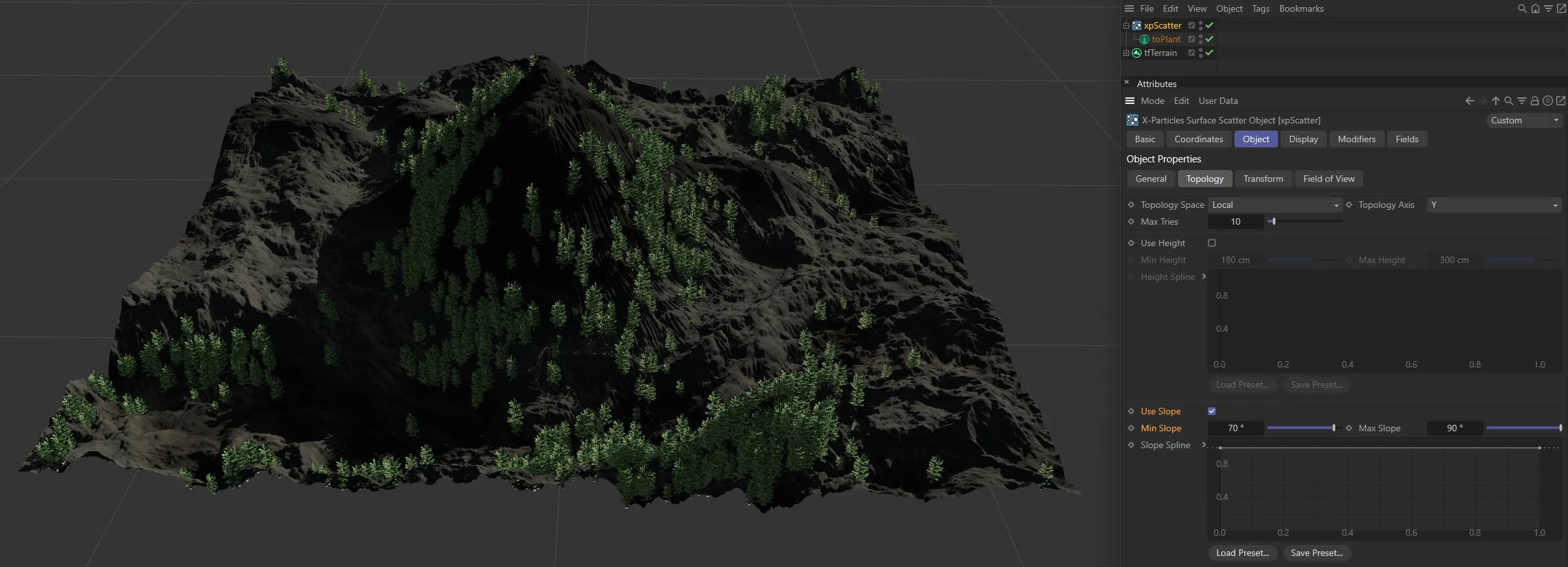
In this second image, Min Slope is now raised to 70 degrees, so scattering only takes place on the steepest slopes, within the 20 degree range.
The opposite is now true, with Min Slope set back to 0 (zero) degrees and Max Slope lowered to 20 degrees, and only the flattest 20 degrees now sees scattering.
Slope Spline
Section titled “Slope Spline”This is identical to the spline used for height-based scattering, but for the slope instead.
Use Curvature
Section titled “Use Curvature”Tick this box to control scattering from the curvature in an object.
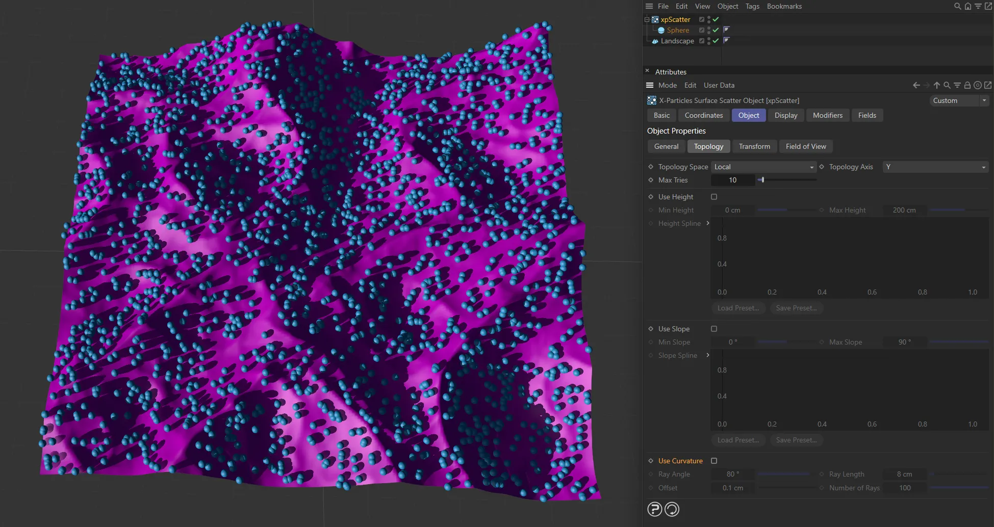
Use Curvature disabled.
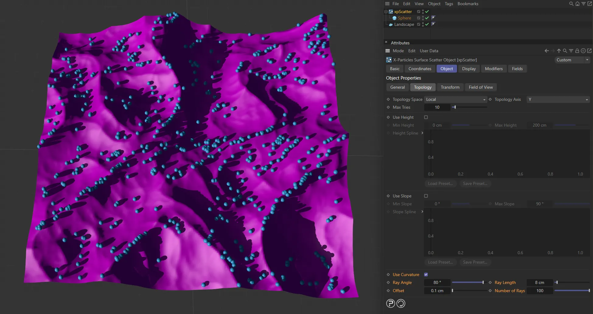
Use Curvature enabled.
Curvature is the folds and other areas where polygons are closely adjacent to others and at an angle to one another.
It is the same principle as ambient occlusion, but in this case objects accumulate in the ‘shadowed’ area.
If you try to scatter objects in the crevices on a Sphere, for example, no objects will be generated, as it has no crevices.
Curvature can also apply to ridges in the object, rather than folds.
The way this works is that the emitter will select an emission point for a particle.
‘Rays’ are then emitted from that point and, if they hit another polygon at a suitable angle from the one containing the emission point, within the specified range, a particle is emitted.
Ray Angle
Section titled “Ray Angle”The polygon hit by a ray must be at an angle to the source polygon by less than this value.
For most purposes the default value of 80 degrees will be fine.
If you reduce it, you will see fewer objects generated and playback will take longer, but on curved surfaces the object placement may be more restricted to the curvature.
Ray Length
Section titled “Ray Length”The distance between the point the ray hits and the source point must be less than this value for objects to be generated.
If you make this too large, objects may be placed on polygons some distance away and which do not even form a curved area with the source polygon.
Offset
Section titled “Offset”If the ray source point is the same as the emission point generated by the emitter, it will register an immediate hit on itself.
This is not useful so the ray source point is offset by this value along the surface normal.
You can almost always leave this at the default, but if you have a very small model or one where polygons are extremely close together, you might need to reduce it.
Number of Rays
Section titled “Number of Rays”This is the number of rays emitted from the generated source point in order to find another polygon nearby.
The default of 100 should be fine in almost all cases.
If you find the playback is slow, you can reduce this value at the expense of accuracy (some adjacent polygons may be missed and a particle therefore not emitted).
If you have a mesh with multiple separate parts (and the Cinema 4D Figure primitive is built like this) you can add the mesh hierarchy as the child of a Connect object and use that as the surface object.
Transform tab
Section titled “Transform tab”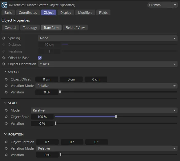
xpScatter Transform tab settings.
Spacing
Section titled “Spacing”Set as None, by default, when objects are scattered, it is quite likely that some or many will overlap; you can avoid this by using this menu.
The alternatives are: Kill and Push.
Do nothing and accept overlapping objects.
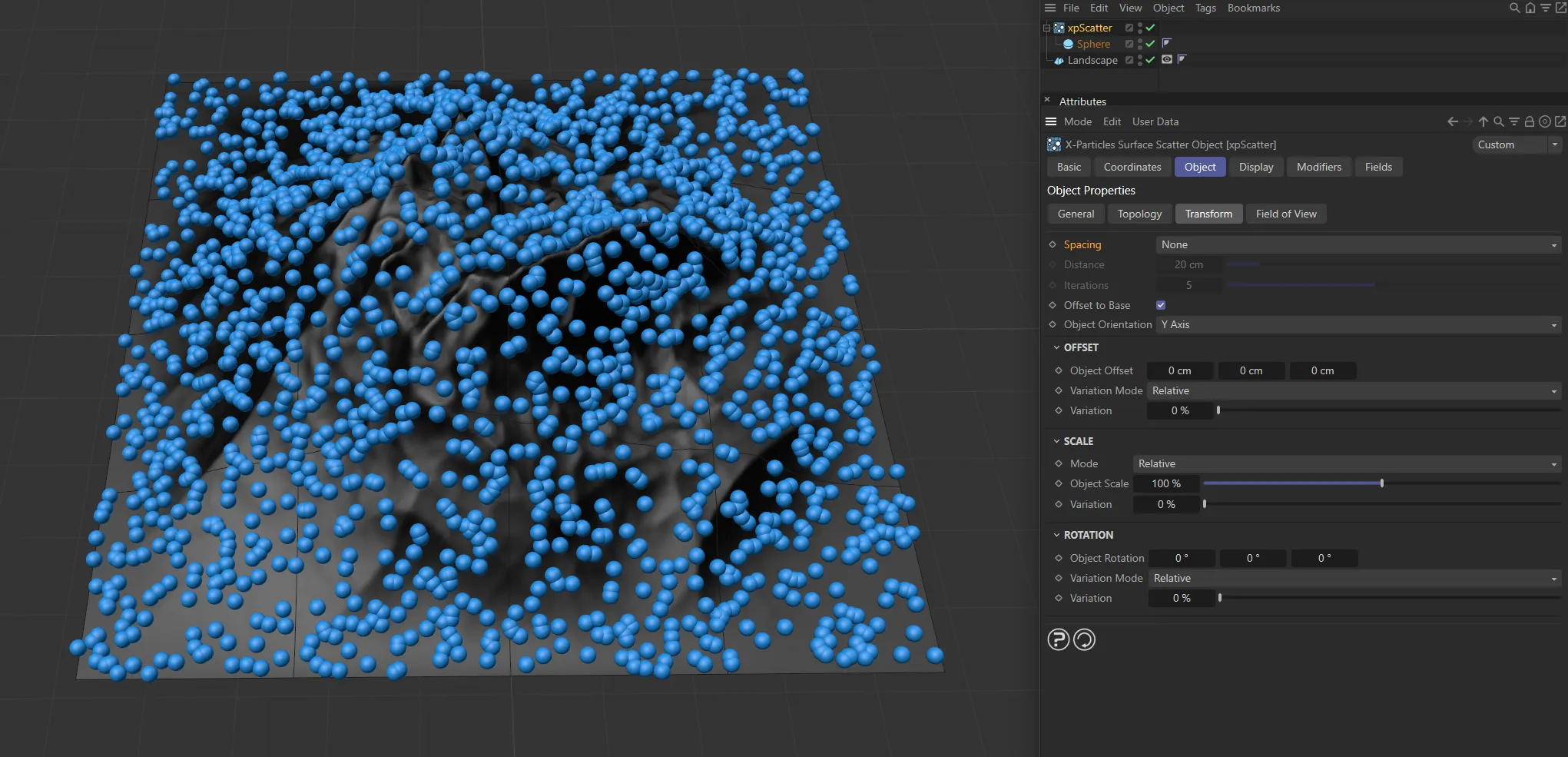
Spacing set as None.
Kill all objects which are within the distance of one another given in the Distance setting.
This can result in a marked reduction in the number of generated objects, but is very fast.
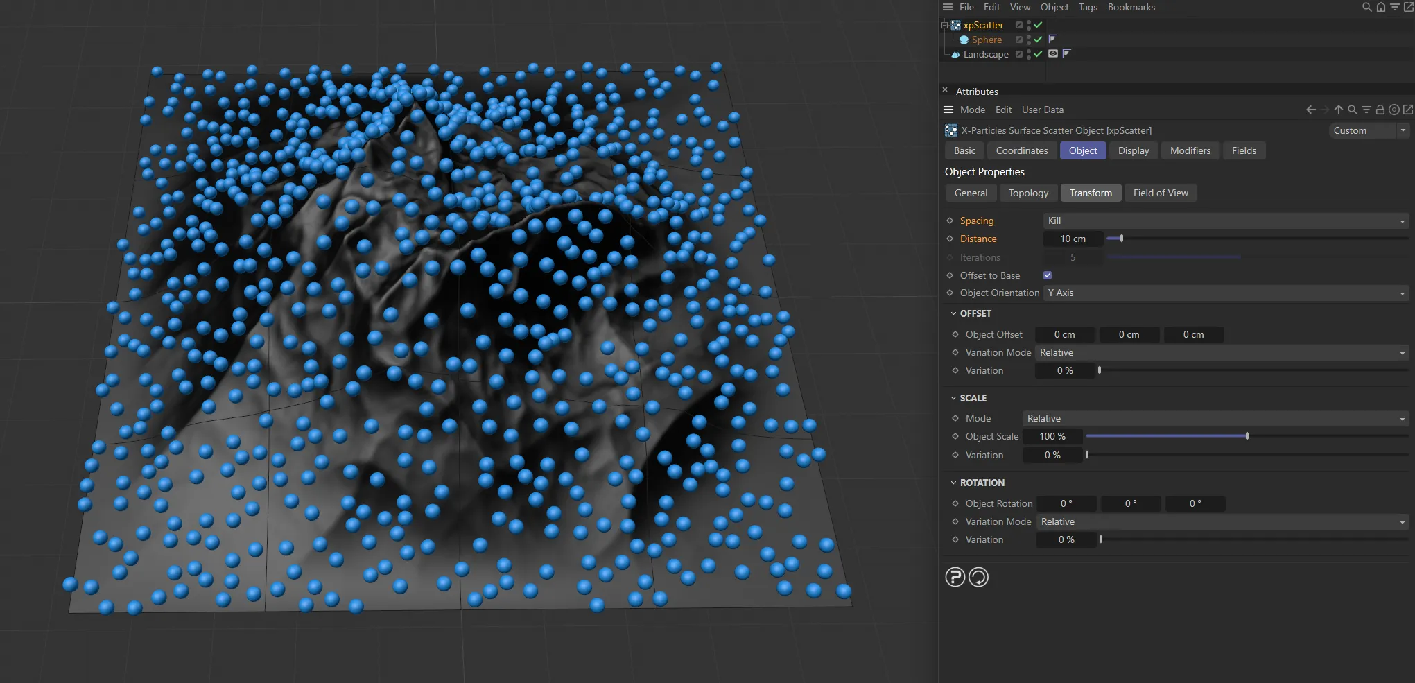
Kill is set to 10cm, in this image.
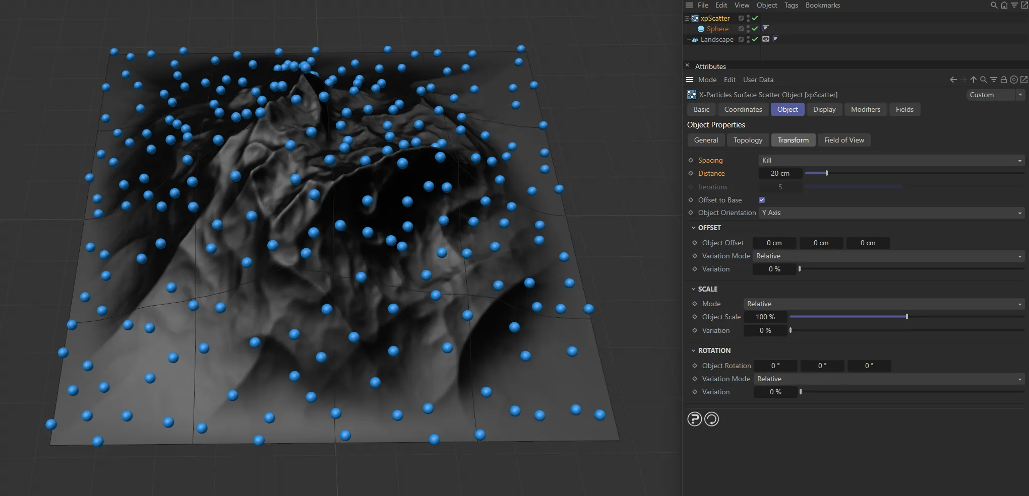
With Kill increased to 20cm, there is an increase in the space around the particles.
Instead of killing objects which are too close together, this option will try to push them apart.
xpScatter will try to separate objects which are closer than the Distance setting.
For this reason, one iteration is not always sufficient.
By increasing the value in Iterations, the push apart algorithm is executed more than once and gives a more accurate result.
However, with a large number of objects, this can be very slow.
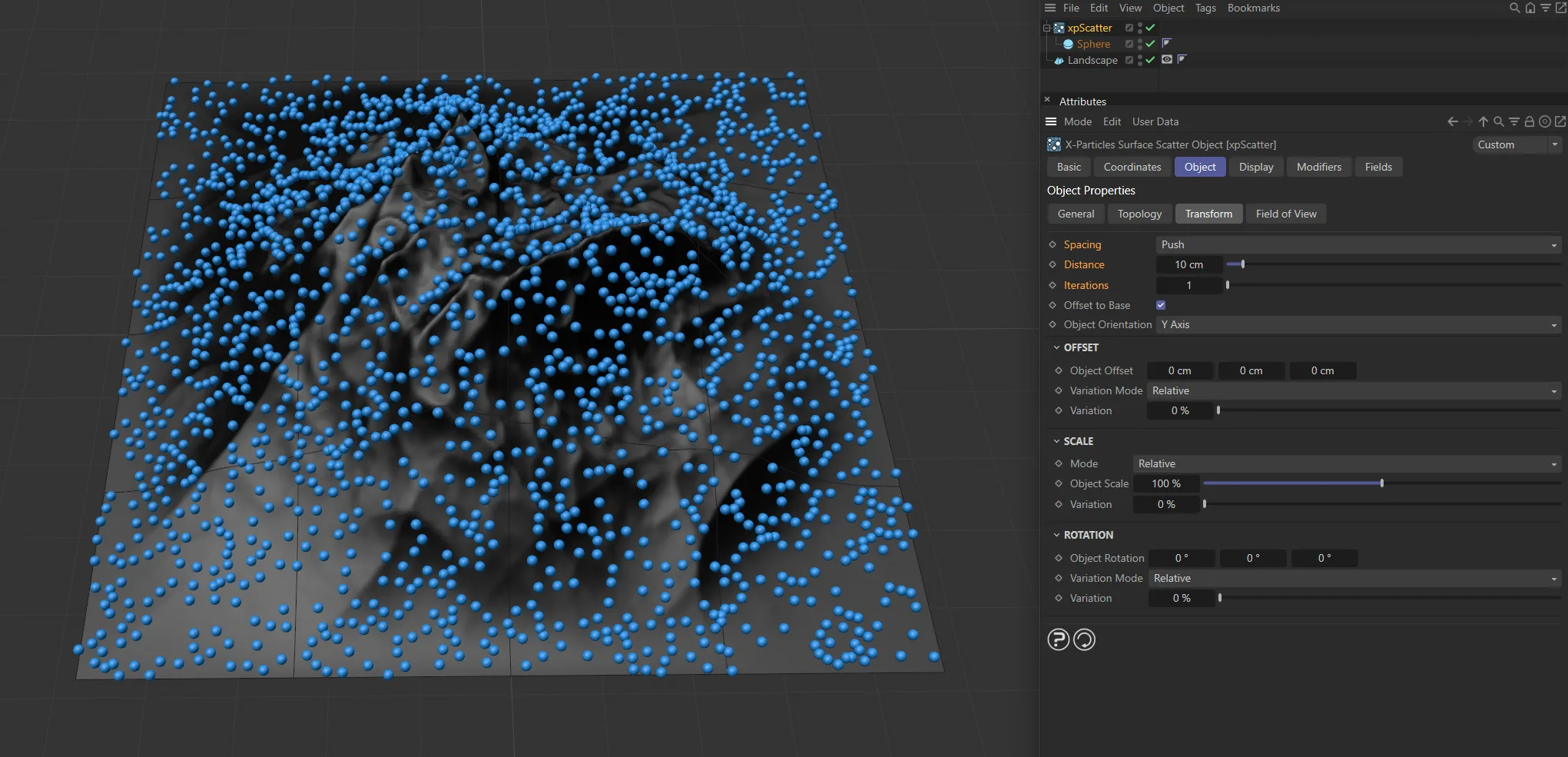
In these images, Spacing is set to Push, with a Distance of 10cm. This first image has Iterations set to 1.
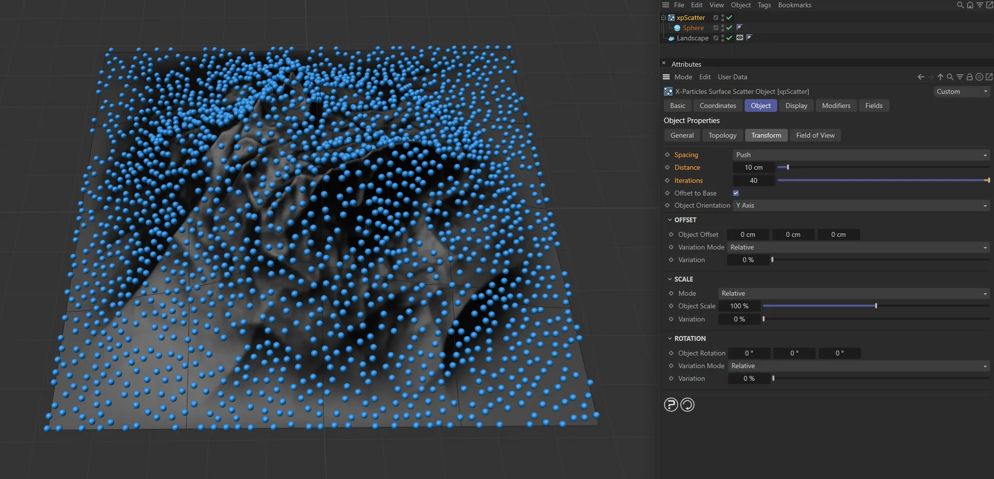
In this second image, Iterations is increased to 40.
Distance
Section titled “Distance”If two objects are closer together than this distance, they will either be killed or pushed apart, depending on the Spacing setting.
Iterations
Section titled “Iterations”The number of iterations to use if Spacing is set to Push.
Offset to Base
Section titled “Offset to Base”Ideally, the objects to be scattered will have their axis located at the point which you want to be touching the surface.
A tree, for example, would probably have its axis located at the bottom of the trunk, where the roots start, so that when placed on the surface the tree doesn’t float above the surface and isn’t buried in it.
However, this isn’t always possible - for example, a parametric object such as the Cylinder primitive will always have the axis halfway along its length and that cannot be altered unless it is made editable.
In some cases, you can overcome this by enabling this parameter.
The xpScatter object then assumes that the axis is located halfway along one of the object’s axes and adjusts its position on the surface so that its base rests on the surface.
This works well with symmetrical objects, where the axis is located in the object center, but with other objects with an offset axis, it doesn’t work as well.
In those cases, the only option is to adjust the axis position within the object.
You could also make the object the child of a null object and adjust the position of the null relative to the child so that the null’s axis is at the required position.
This is where the Object Orientation (below) parameter comes in.
Object Orientation
Section titled “Object Orientation”Set as Y Axis, by default, whether or not you need to change this menu depends on which axis you want the object to point away from the surface along.
The alternatives are X Axis and Z Axis.
Offset
Section titled “Offset”You can use the parameters in this section to offset the object position from its initial value when generated.
Object Offset
Section titled “Object Offset”The scattered objects are given an initial position on the surface but this can be changed with these values.
Negative values are possible.
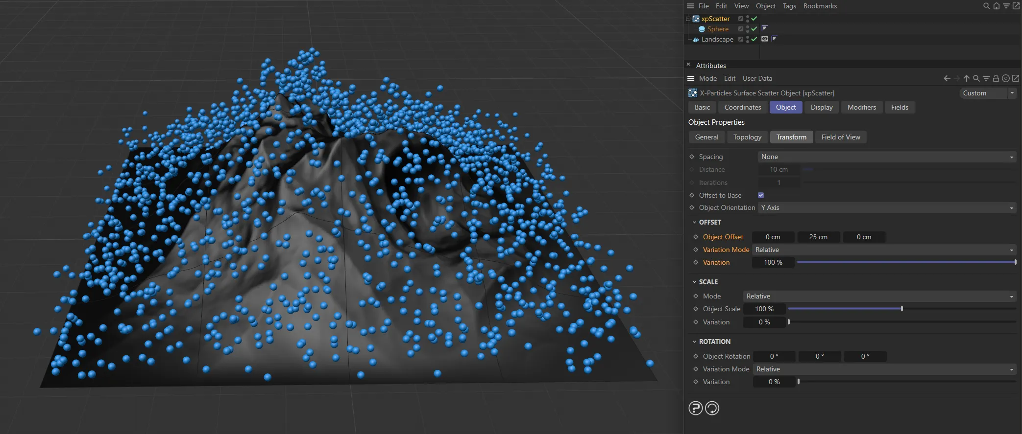
Object Offset of 25cm on the Y axis and 100% Variation set.
Variation Mode
Section titled “Variation Mode”Set to Relative, by default, if you want to add some variation to the offset values you have input, you can do it in one of two ways.
The alternative option is Absolute.
Relative
Section titled “Relative”In this mode, the variation is set as a percentage of the added offset, so 0 (zero) % represents no variation.
This is simple to use but this mode adds variation equally to all three axes.
If you want to vary the offset along an individual axis, select Absolute mode instead.
Absolute
Section titled “Absolute”If you select this mode, the variation is in absolute values and the interface changes slightly, to give variation options along the different axes.
Variation
Section titled “Variation”This enables you add variation to the added offset.
It is either a percentage value (in Relative mode) or actual values in scene units (Absolute mode).
You can use the parameters in this section to alter the object size.
Set to Relative, by default, by default objects are generated at the same size they have when added to xpScatter.
Of course, you might want to make them smaller or larger, which you can do in one of two ways.
The alternative setting is Absolute.
Relative
Section titled “Relative”In this mode, the scale is set as a percentage of the initial size, so 100% is the same as that size.
This is simple to use and you can add variation to the size of the objects with the Variation slider.
This mode scales the object equally along all three axes.
If you want to scale the object along an individual axis, select Absolute mode instead.
Absolute
Section titled “Absolute”If you select this mode, you can change the scale differently along individual axes and the interface changes slightly to reflect this.
You can also add variation differently along different axes.
This is the most flexible mode but requires more input from you.
Object Scale
Section titled “Object Scale”A percentage of the initial scale (in Relative mode) or actual scale values (in Absolute mode).
Variation
Section titled “Variation”This enables you to vary the size of the scattered objects.
It appears either as a percentage slider or as a vector input, depending on the selected mode.
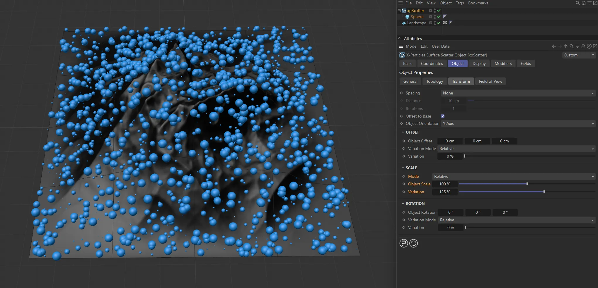
Here, there is 125% Variation added to the Object Scale setting.
Rotation
Section titled “Rotation”You can use the parameters in this section to rotate the scattered objects.
Object Rotation
Section titled “Object Rotation”By default, objects are rotated to match the particle orientation and direction.
If you need to add additional rotation you can do so in this field.
This field is a vector representing HPB (heading, pitch, bank) rotation.
An issue you may encounter concerns the axis to rotate around.
For example, suppose a tree has its height along the Y axis, you have correctly selected Y Axis in Object Orientation (see above) and you want to rotate the tree around its own Y axis.
In this example you would choose the H value in this field (the first one) but if you selected one of the other axes in Object Orientation, you would need to use the P or B values instead.
Variation Mode
Section titled “Variation Mode”Set to Relative, by default, if you want to add some variation to the rotation values you have input, you can do it in one of two ways.
The alternative option is Absolute.
Relative
Section titled “Relative”In this mode, the variation is set as a percentage of the added rotation, so 0 (zero) % represents no variation.
This is simple to use but this mode adds variation equally to all three axes.
If you want to vary the rotation along an individual axis, select Absolute mode instead.
Absolute
Section titled “Absolute”If you select this mode, you can change the rotation differently along individual axes and the interface changes slightly to reflect this.
Variation
Section titled “Variation”This enables you add variation to the added rotation.
It is either a percentage value (in Relative mode) or actual values in degrees (Absolute mode).

Variation set at 0 (zero) %, with no Object Rotation set.
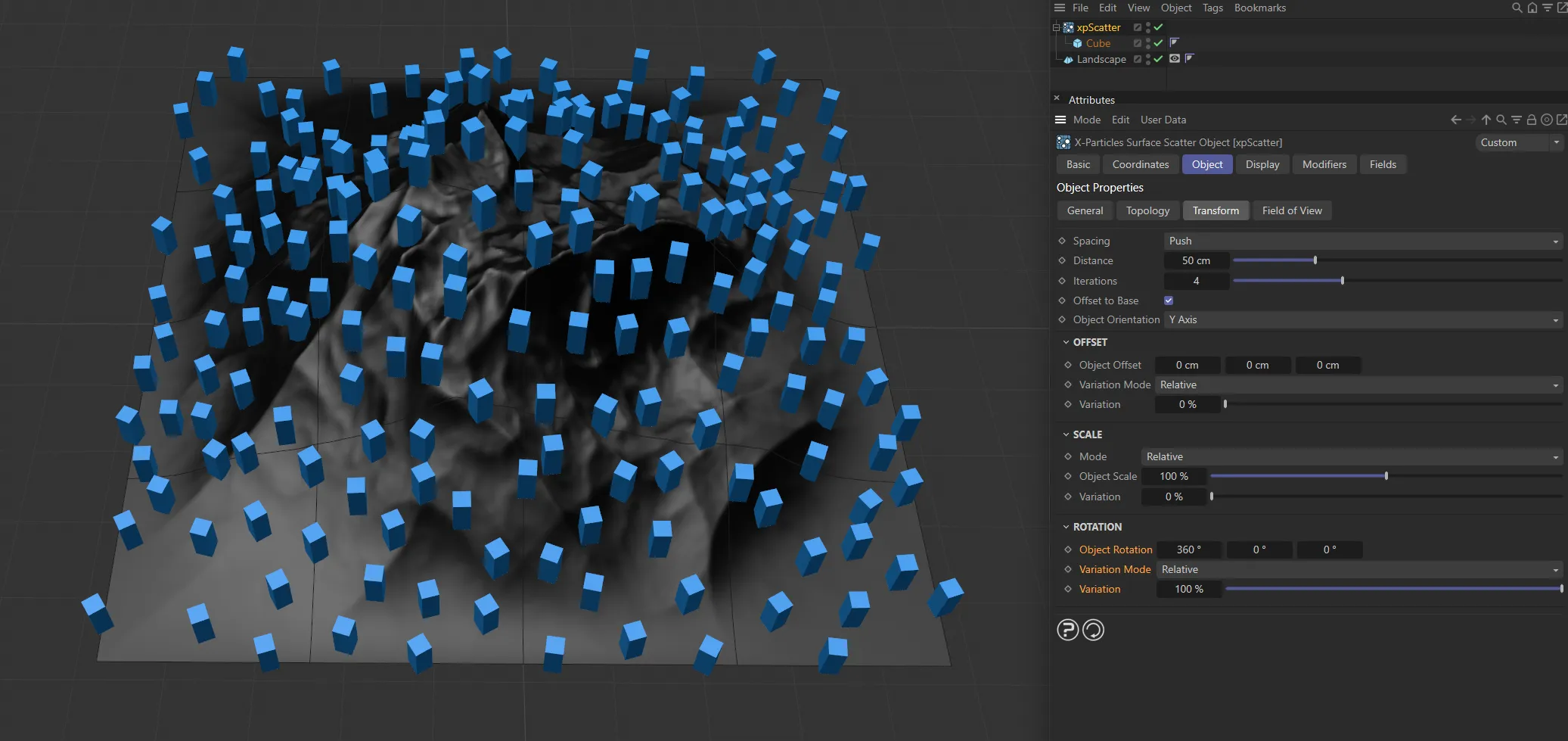
Object Rotation at 360 degrees on the heading and 100% of Variation set.
Field of View tab
Section titled “Field of View tab”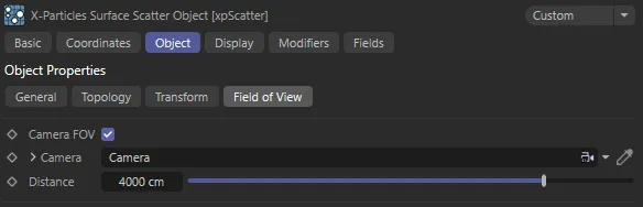
xpScatter Field of View tab settings.
Camera FOV
Section titled “Camera FOV”If enabled, objects will only be scattered within the field of view of the camera in the Camera link field.
Camera
Section titled “Camera”Drag the camera whose field of view you want to use into this field.
Distance
Section titled “Distance”This is the maximum distance from the camera at which objects will be generated.
No object will be generated if they are further away from the camera than this value.
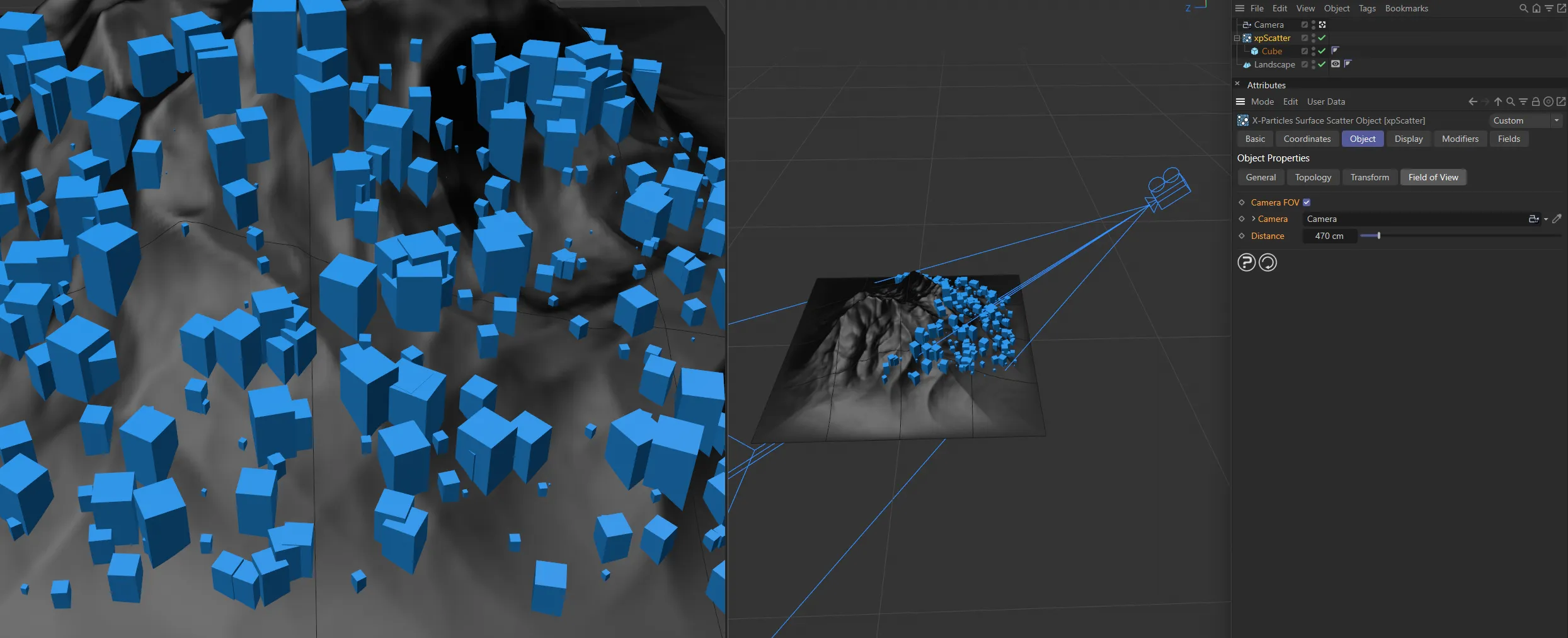
Camera FOV enabled, with a camera dropped in the Camera field and 470cm of Distance set.
Display tab
Section titled “Display tab”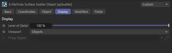
xpScatter Display tab settings.
Level of Detail
Section titled “Level of Detail”If you reduce this value, you will see fewer generated objects in the scene, which may speed up the viewport and playback.
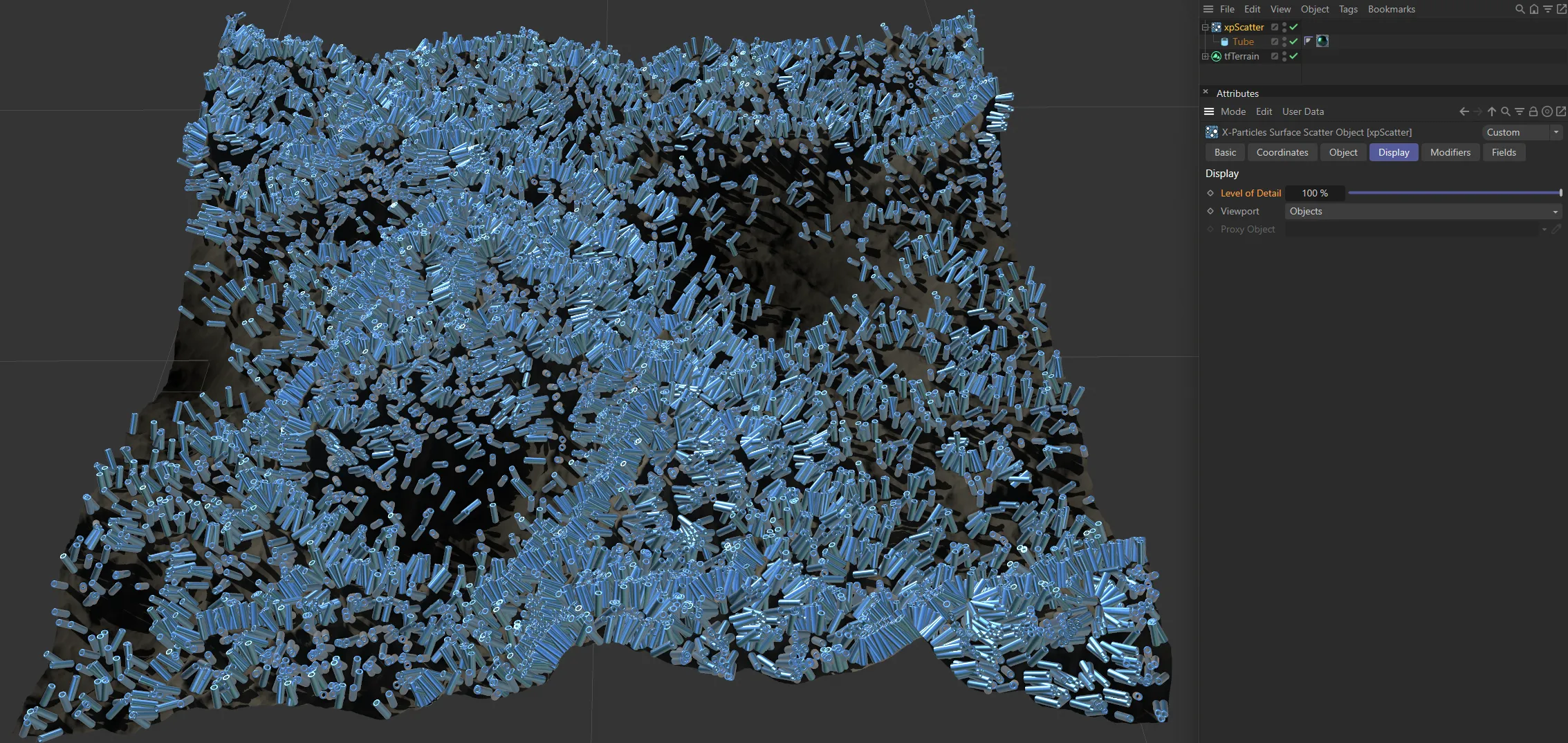
Level of Detail set at 100%.
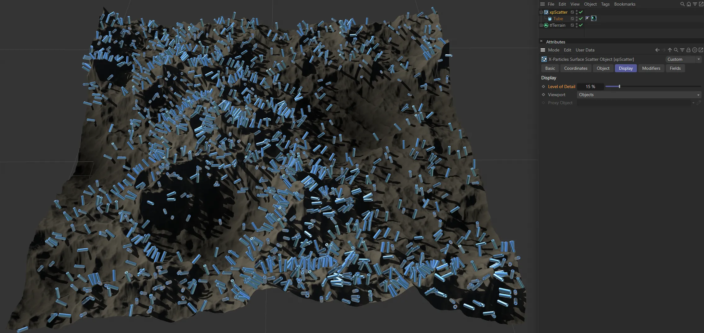
Level of Detail reduced to 15%.
Viewport
Section titled “Viewport”Set as Objects, by default, this menu controls what you see in the viewport.
The alternative settings are: None, Particles, Proxy and Cubes.
No generated objects are displayed.
Particles
Section titled “Particles”Objects are not displayed, but the underlying particles are shown.
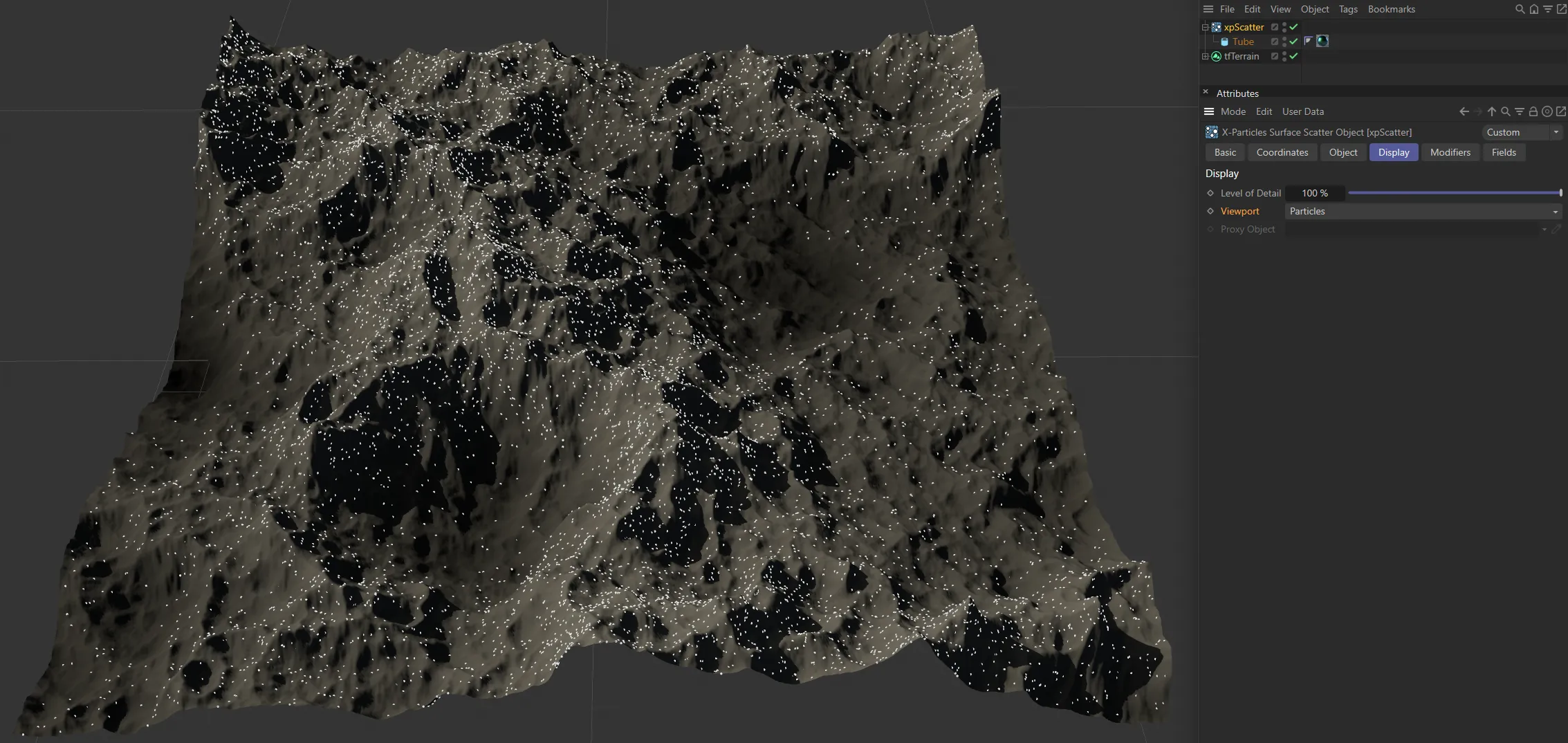
Viewport set to Particles.
Instead of the generated objects you can substitute a simple proxy object instead.
Drag the object to use into the Proxy Object field.
If that is left empty, the generated objects are shown.
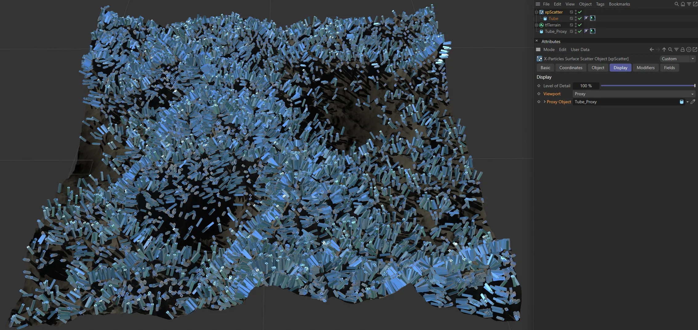
In this image, the Viewport is set to Proxy, with a low poly version of the source object linked in the Proxy Object field.
The generated objects are replaced by simple Cubes.
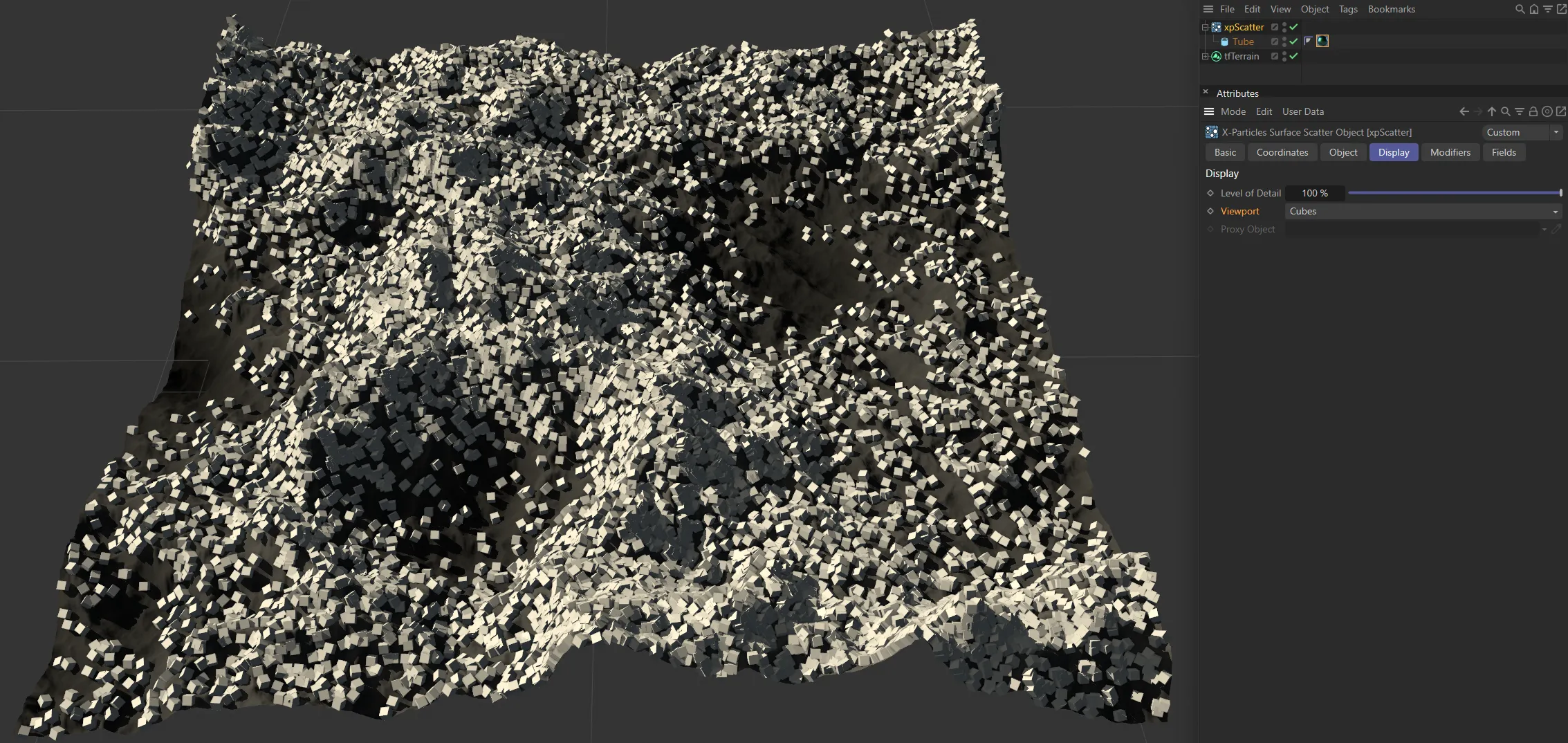
Here, Viewport is set to Cubes.
Objects
Section titled “Objects”The actual generated objects are shown.

Viewport set to Objects.
Proxy Object
Section titled “Proxy Object”Only available if Viewport is set to Proxy.
Drag the object to use as a proxy into this link field.
Modifiers tab
Section titled “Modifiers tab”
xpScatter Modifiers tab settings.
xpScatter uses an emitter to determine where to place the generated objects.
This emitter can be affected by particle modifiers in the same way as any other emitter.
However, to prevent other modifiers you add to the scene affecting the emitter internal to xpScatter, the emitter’s modifier list is set to Include rather than Exclude.
This means that if you want a modifier to affect the inbuilt scatter emitter, you must add it to this list.
Typically, the most useful modifiers are likely to be the xpScale and xpSpin modifiers, but you can add any modifier here.
Modifiers
Section titled “Modifiers”Drag the modifiers you want to affect the scatter particles into this list.
Fields tab
Section titled “Fields tab”You can use the Fields options to control where xpScatter operates.
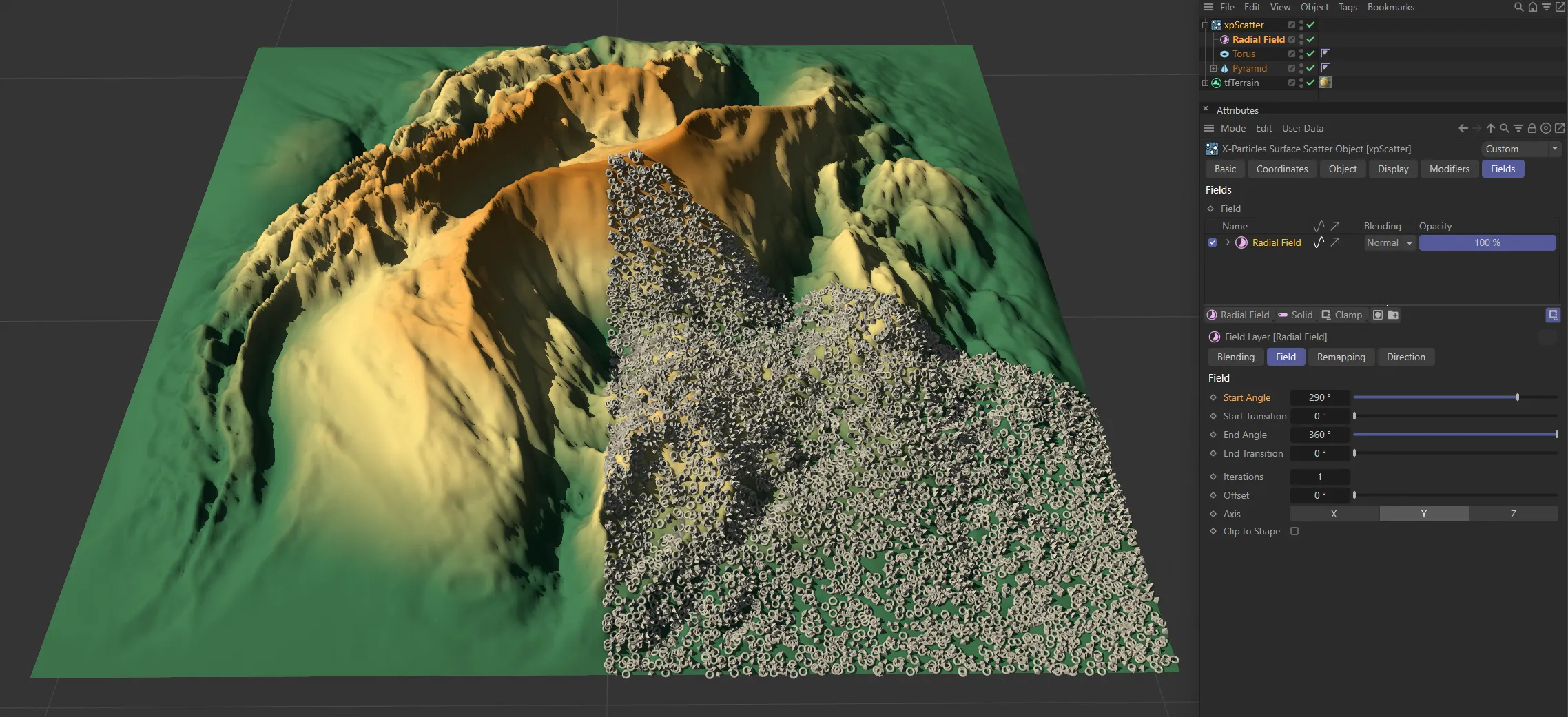
In this image, there is a Radial Field set, controlling where the objects are being scattered.
Copyright © 2026 INSYDIUM LTD. All rights reserved.