xpOpenVBDMesher
xpOpenVDBMesher generates sparse volumetric data which is used to create dynamic meshes or fog volumes from particles and scene objects.
The mesher is supplied with three items of data for each particle (or vertex, if the source object is a polygon object or spline).
These are the particle position, its radius and its velocity.
For polygon or spline objects, the radius is arbitrarily set to 1 and the velocity to zero, but for particles, the actual values from the particle are used.
With this data, xpOpenVDBMesher constructs a three-dimensional grid to enclose all the points; each cell in this grid is a voxel.
Voxel size can be changed with Voxel Size setting.
Each voxel can be outside the surface to be generated, or inside it, or actually on or near the surface itself.
The band of voxels, which are the ‘active’ voxels, are at a narrow surface; its width can be altered by changing the Half Width setting.
All other voxels are considered ‘inactive’ and play no part in forming the surface.
The mesher then constructs a virtual sphere around each particle.
The size of this sphere is the particle radius (or 1 if the object is not an emitter).
If the spheres overlap they will be unioned, much as two sphere objects might be joined by a Cinema 4D Boolean object.
If the sphere is smaller than the Min Radius setting or larger than the Max Radius setting, it will not be included in the mesh.
Finally, if there are voxels within this sphere that are part of the narrow band, the sphere will be meshed, and the size of the generated polygons will depend on the voxel size.
General tab
Section titled “General tab”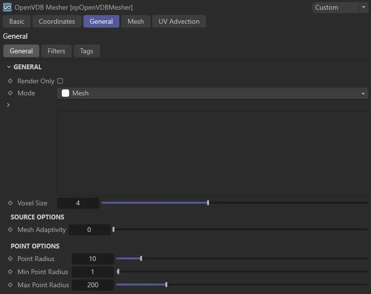
General tab settings.
Render Only
Section titled “Render Only”If enabled, no mesh will be visible in the viewport and will only be seen when the scene is rendered to the viewport or picture viewer.
Set as Mesh, by default, the mesher can operate in four alternative modes: Spheres, ExplosiaFX, Fog and Voxels.
These each have their own set of parameters.
This generates a polygonal mesh from the object(s) in the Sources list.
The resulting mesh depends on the options chosen for the source object.
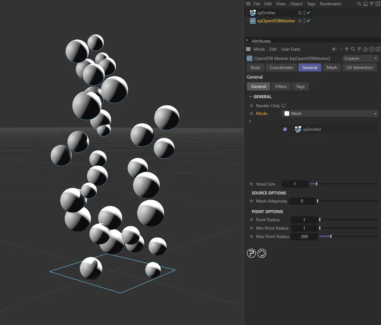
Mesh mode.
Spheres
Section titled “Spheres”In this mode, instead of creating a surface, the mesher will derive a voxel grid - which will not be displayed - from the object and then fill that with spheres.
The parameters in this section allow you to control the sphere generation.
As with the Mesh option, the result depends on the source object options.
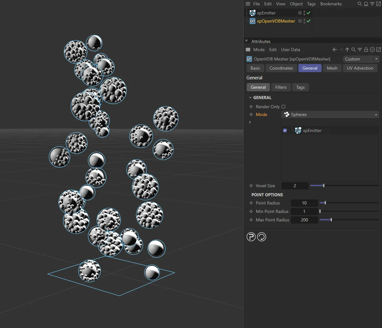
Spheres mode.
ExplosiaFX
Section titled “ExplosiaFX”This mode generates an OpenVDB volume which can be rendered with an Explosia FX object.
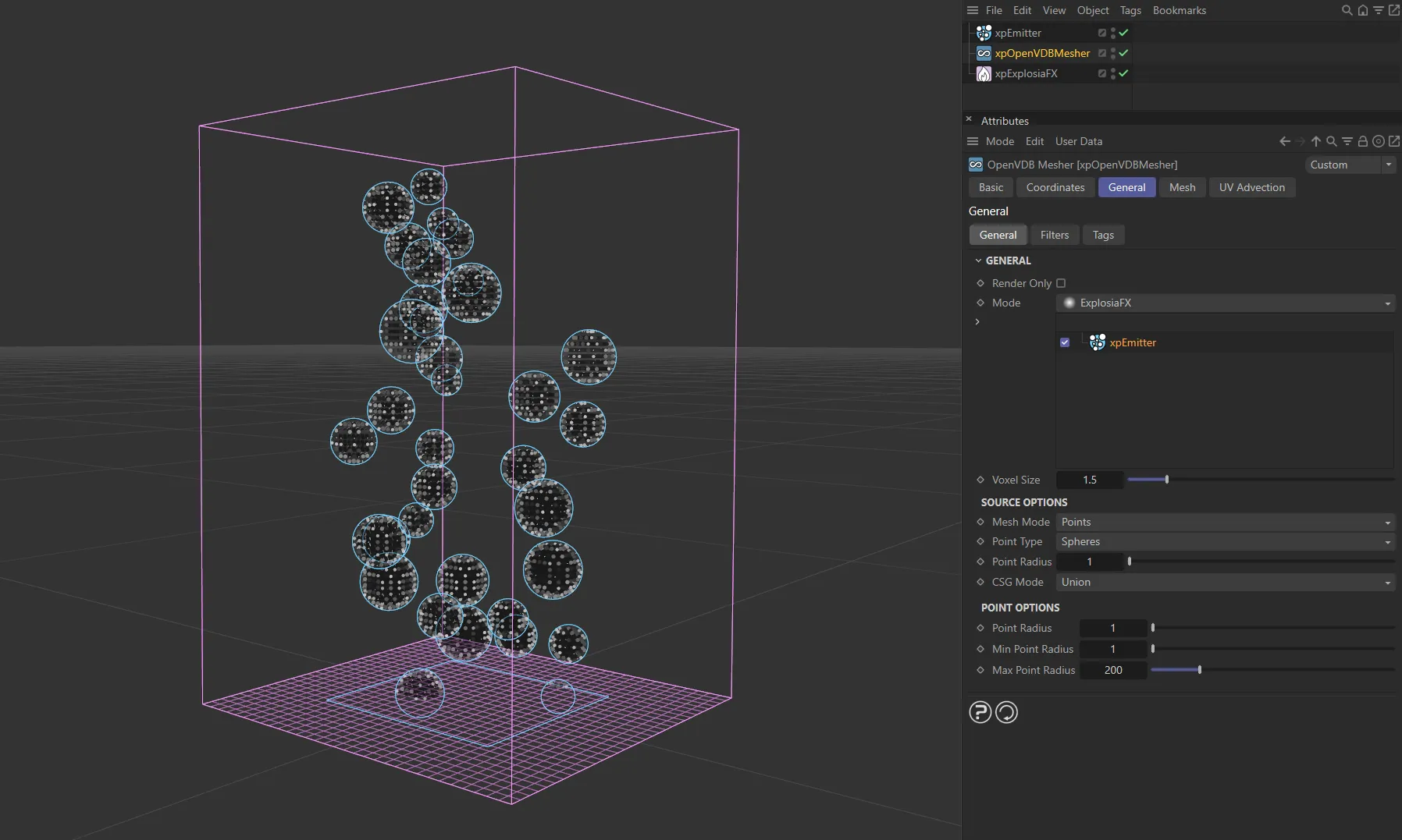
ExplosiaFX mode.
This mode generates an OpenVDB volume rather than a mesh.
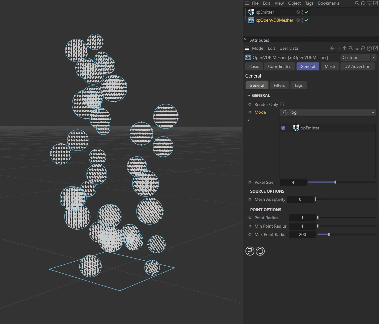
Fog mode.
Voxels
Section titled “Voxels”In this mode, the object is displayed as created by voxels.
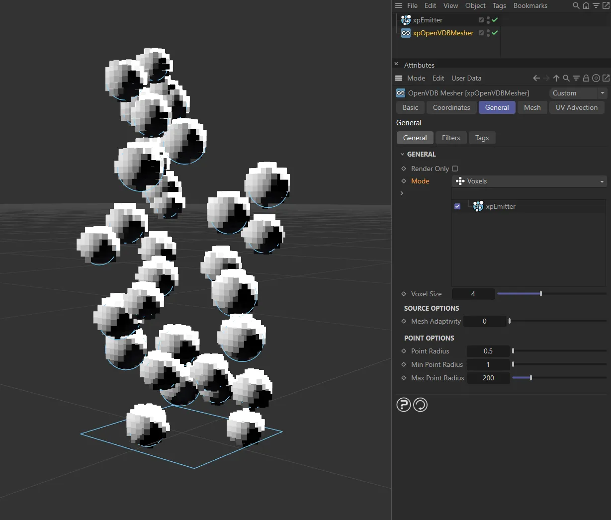
Voxels mode.
Voxel Size
Section titled “Voxel Size”The voxel size when the mesher is shown in the viewport during scene editing.
Generally speaking, this should be kept as large as possible for maximum speed in the viewport.
As the voxel size is lowered, the resolution of the mesh increases and any animation in the viewport will be slower.
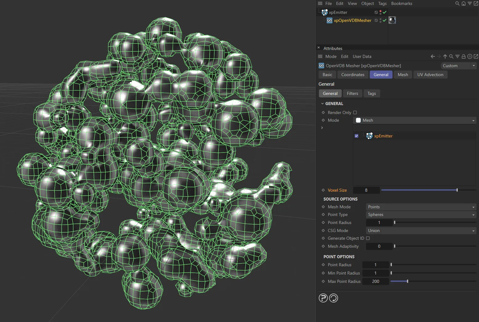
In this image, the Voxel Size value is 8.
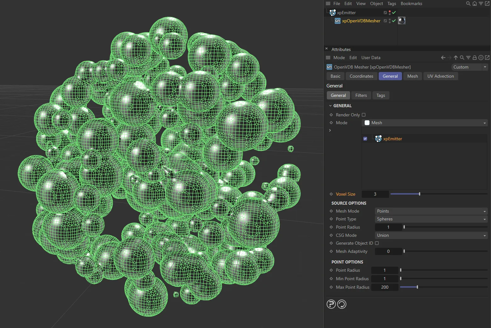
The Voxel Size is reduced to 3 here.
Source Options
Section titled “Source Options”Mesh Mode
Section titled “Mesh Mode”This menu enables you to choose the mode used when building the mesh.
It has three options: Points, Surface and Volume.
Each option has its own parameter options, detailed below.
Points mode
Section titled “Points mode”The mesher will generate small spheres around each vertex.
Point Type
Section titled “Point Type”There are two options: Spheres and Trails.
Spheres
Section titled “Spheres”A sphere is generated around each point (or particle).
In this scene, with a Point Type of Spheres, a sphere is generated around each point in the right-hand mesh.
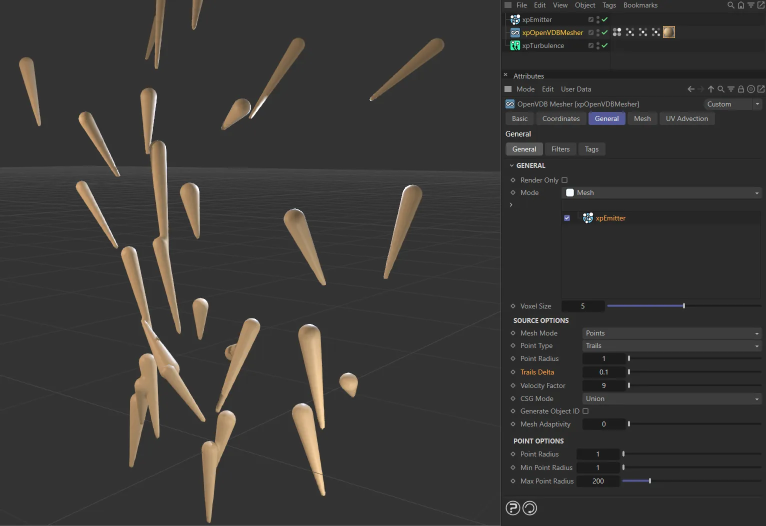
Trails
Section titled “Trails”These are not the same as the splines generated by the X-Particles xpTrail object.
Each trail is a tapering mesh, which forms behind the particle and whose length is dependent on the particle speed.
If you use an object such as a Cube as a source for the mesher, the vertices of the object have no speed so only spheres are produced.
This is the case even if the object is animated, since the vertex speed is zero in relation to the object.
Selecting this option gives you more parameter options.
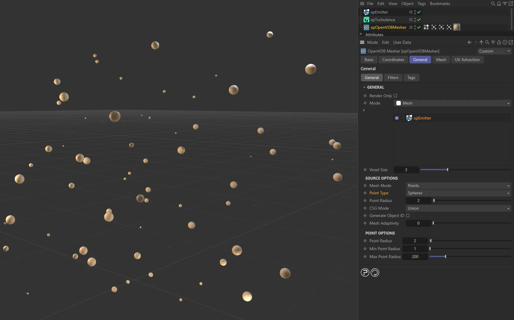
In this first image, the Point Type is set as Spheres.
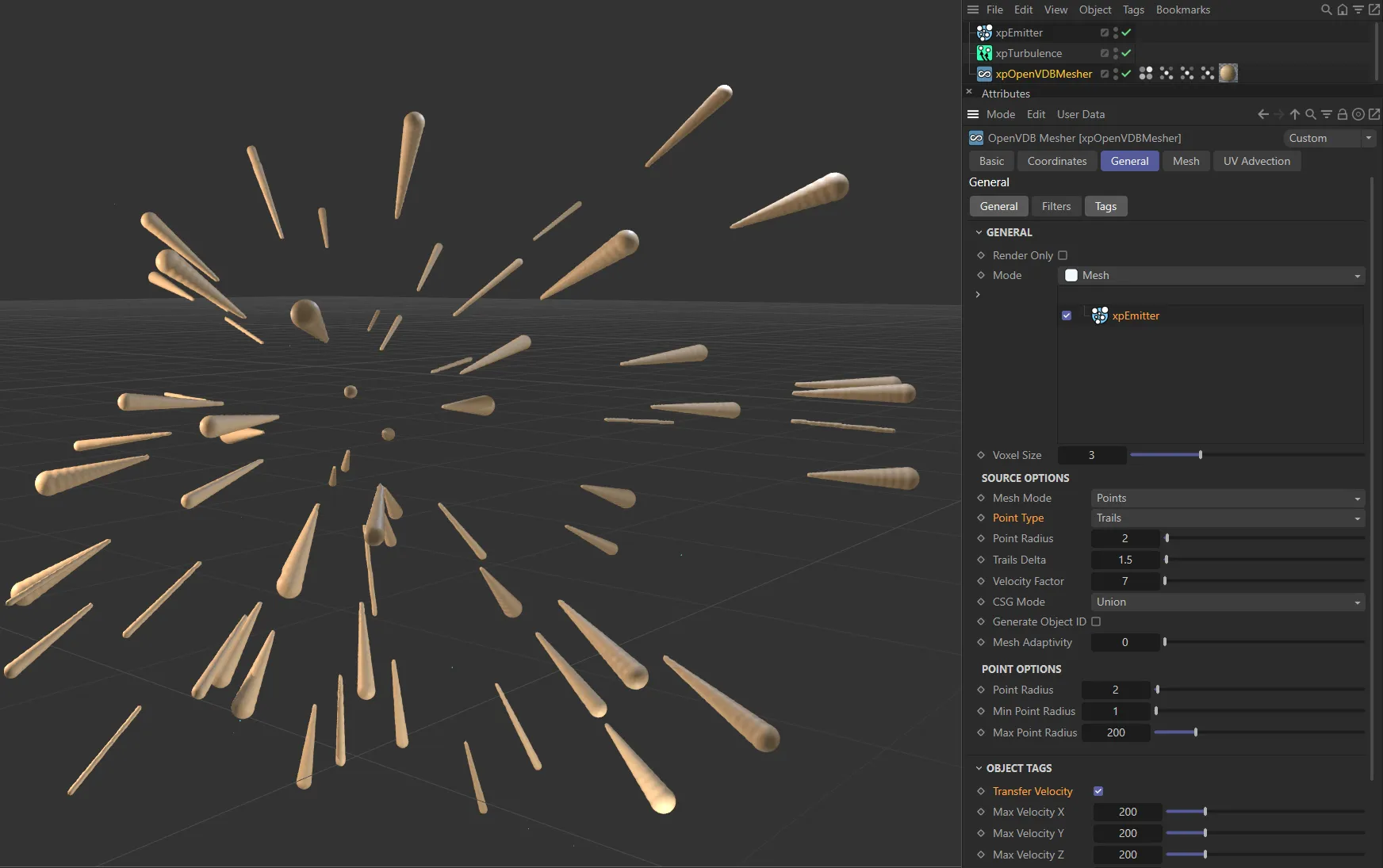
Here, the Point Type has been changed to Trails. Note: For trails to work, Transfer Velocity must be enabled in the Tags tab.
Point Radius
Section titled “Point Radius”This enables you to control the size of the generated sphere.
CSG Mode
Section titled “CSG Mode”Set as Union, by default, this is the method used by the mesher to control how multiple meshes are joined.
The other options are: Intersection and Difference.
The meshes from each source object are joined together to form one mesh.
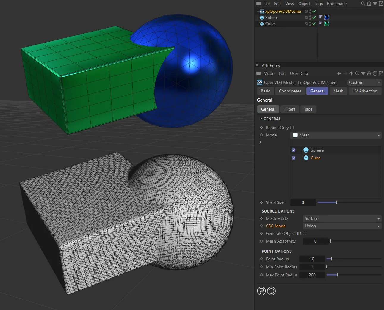
With the CSG Mode set as Union, meshing the Cube and Sphere joined together.
Intersection
Section titled “Intersection”The volume where the objects overlap is meshed.
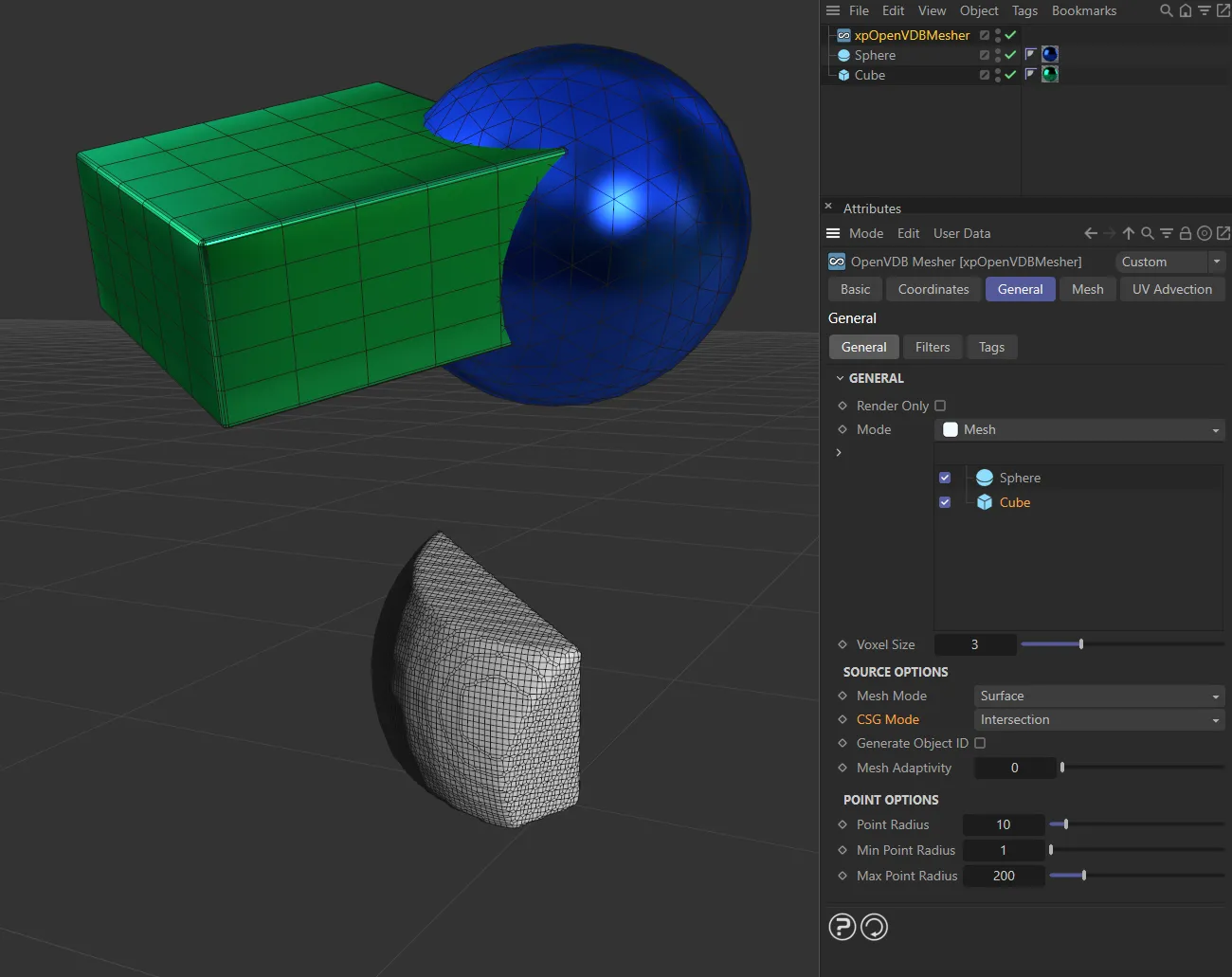
Here, the CSG Mode is Intersection, so only the area where the Cube and Sphere overlap is meshed.
Difference
Section titled “Difference”The volume where the objects do not overlap is meshed.
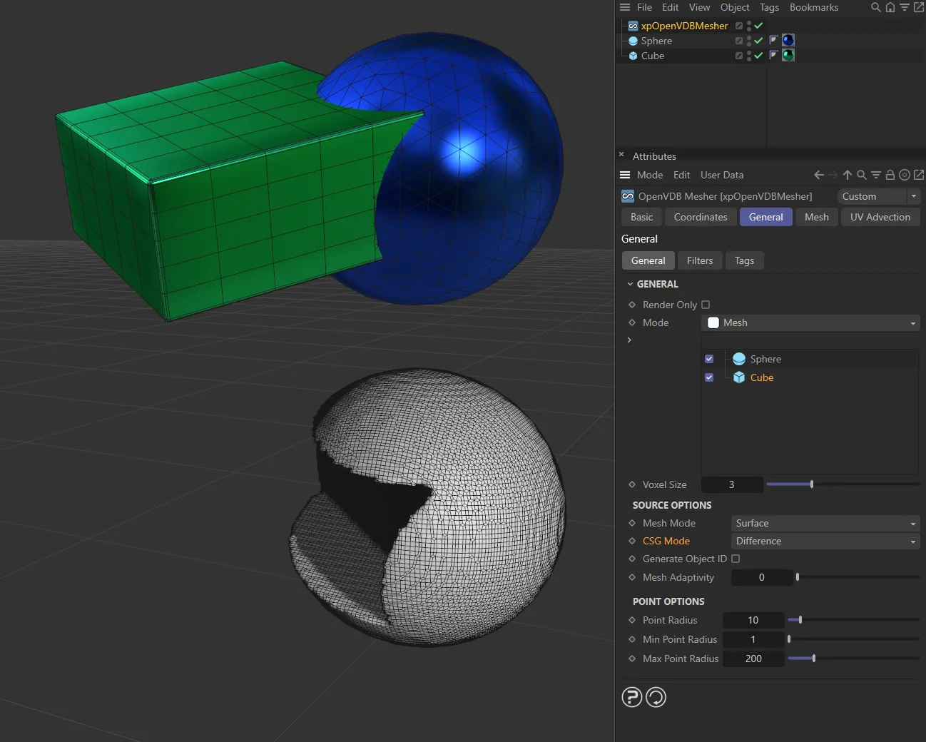
In the CSG Mode of Difference, only the areas of the Cube which do not overlap with the Sphere are meshed.
Generate Object ID
Section titled “Generate Object ID”If this is enabled, the mesher will automatically generate a live vertex map for the mesh derived from the selected source object.
The map can then be used, for example, to color that part of the mesh.
This means that the parts of the mesh derived from different source objects can have different colors.
Important note: Generated vertex maps cannot be cached.
This means that the vertex maps will no longer be visible in the scene when you select one of the tags.
To show the maps again, you will need to delete the Cache tag on the xpOpenVDBMesher; simply emptying the cache from the Cache object is not sufficient.
By increasing the smoothing iterations, the different colors can be blended, allowing the mixing of colors from the different sources.
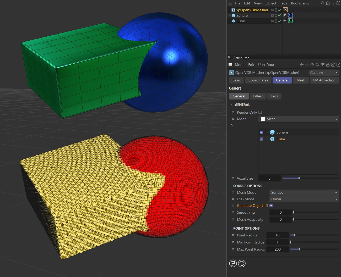
Generate Object ID enabled, generating a vertex map.
Smoothing
Section titled “Smoothing”The number of smoothing iterations to use in the vertex map when Generate Object ID is enabled for a source object.
The higher the value, the smoother the blend between different maps.
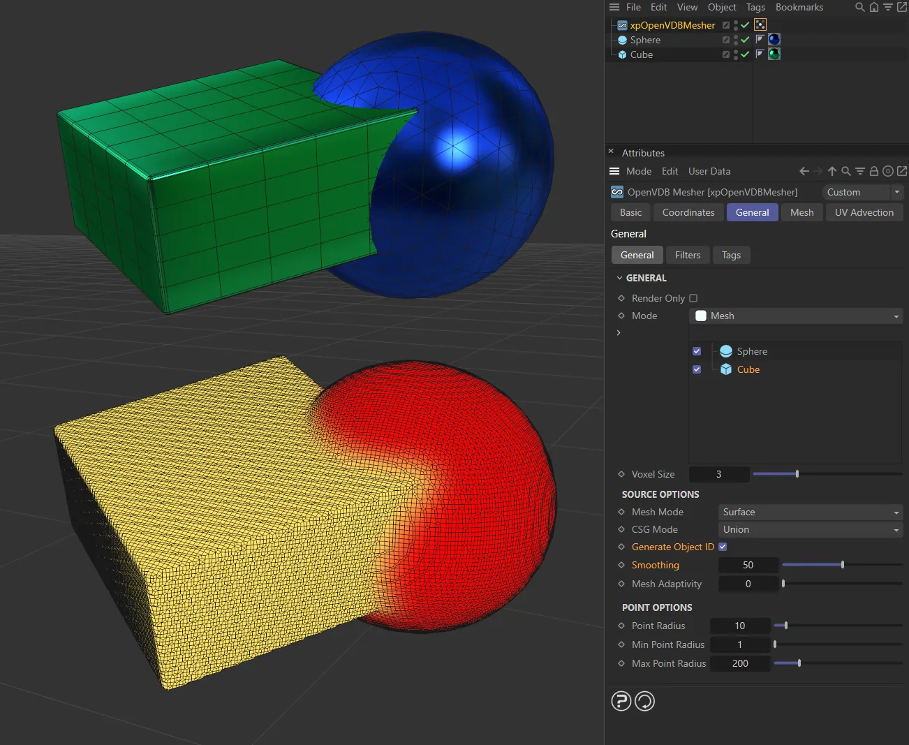
With Generate Object ID enabled and Smoothing set at 200, smoothing the blend area.
Mesh Adaptivity
Section titled “Mesh Adaptivity”This parameter is only available if Mode is set to Mesh.
By increasing it, you can reduce the number of polygons in the mesh but the mesh may look less rounded and not as attractive.
Animation to demonstrate the effect of increasing the Mesh Adaptivity value, reducing the number of polygons in the mesh.
Trails Delta
Section titled “Trails Delta”When Mesh Mode is set to Points and Point Type to Trails, the particle effectively gains a tapered tail behind it; this is built by the mesher as a series of spheres with decreasing radius.
This setting controls how far apart the spheres are drawn.
The farther they are apart, the less they are ‘unioned’ together, so increasing this value may result in the trail being drawn as a series of unconnected spheres.
You can increase this value as much as you like, but as you reduce it the number of computations required significantly increases and, if the value is too small, Cinema 4D may appear as if it has frozen.
To prevent this you cannot set the value to be less than 0.1.
In this image, the Trails Delta is set at 0.1, drawing the spheres close together.
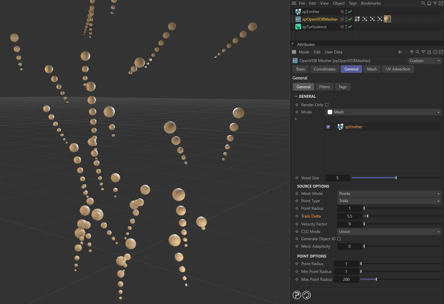
Here, the Trails Delta is raised to 5.5, so the spheres are no longer connected.
Velocity Factor
Section titled “Velocity Factor”With the same settings as above, the length of the tail depends on the particle speed, which leads to a problem in obtaining short trails without reducing particle speed (or long trails without increasing speed).
This animation demonstrates the effect of increasing the Velocity Factor.
This factor is simply a scale applied to the velocity.
It does not change particle speed, but the value passed to the mesher is altered by multiplying by this value.
Reduce it for shorter trails and increase it for longer ones.
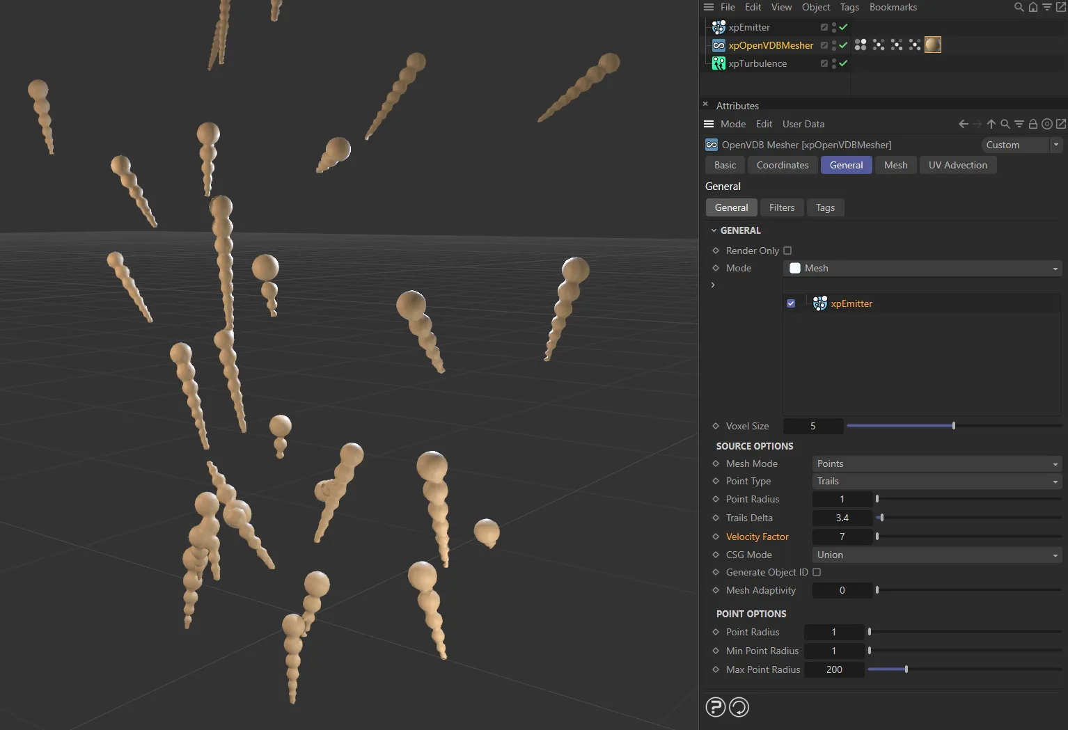
With a Velocity Factor of 7, the trails are longer.
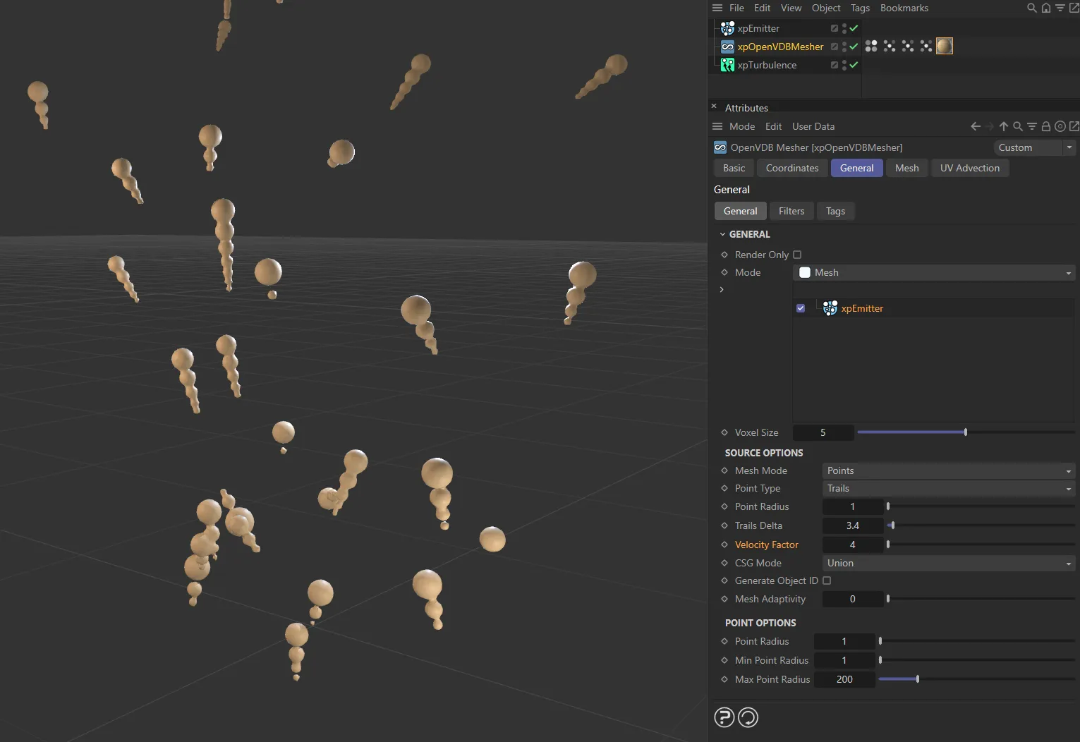
Lowered to 4, the trails are shortened.
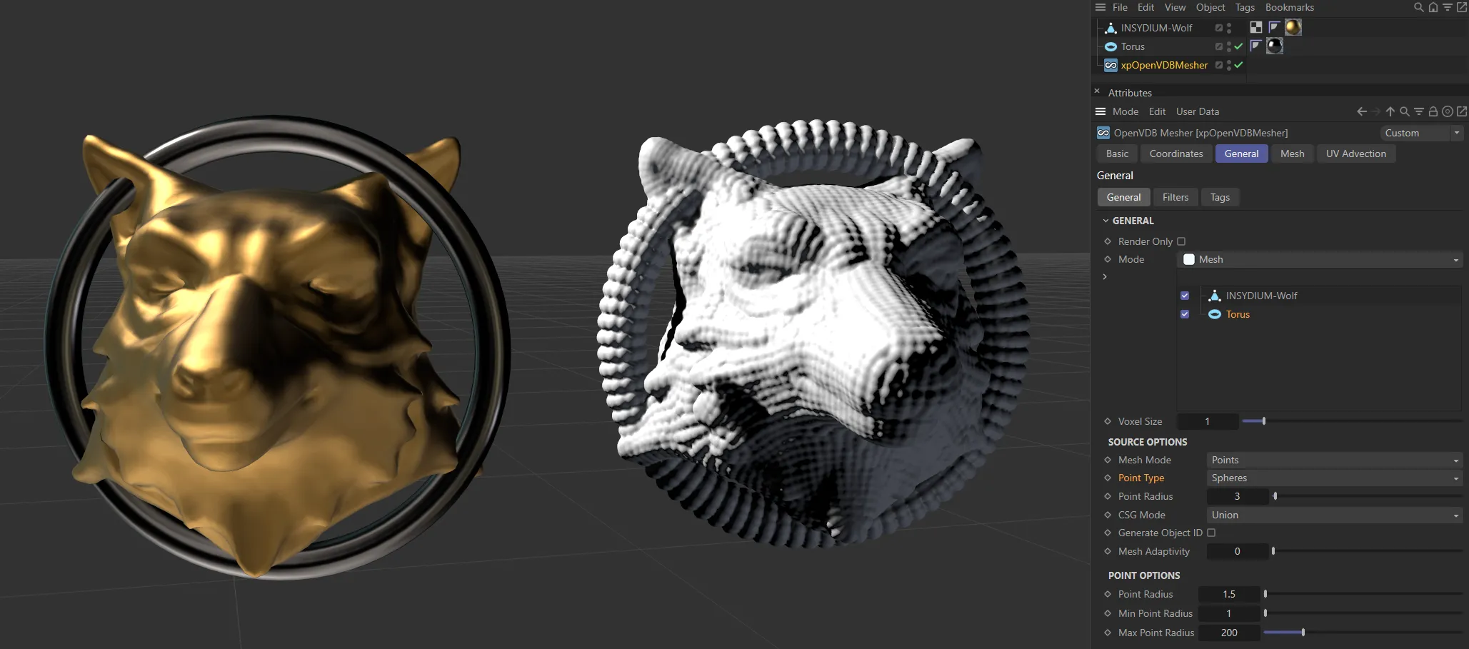
Surface mode
Section titled “Surface mode”The mesher will generate a contiguous surface from the object’s vertices.
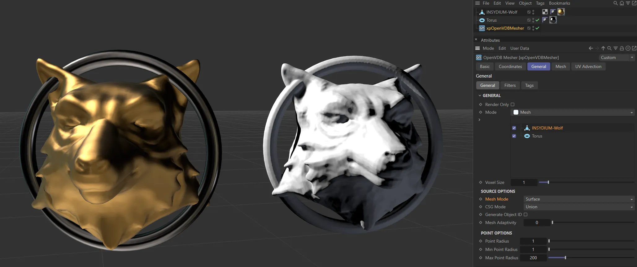
Image showing the Mesh Mode set as Surface, in the right-hand mesh.
CSG Mode, Generate Object ID, Mesh Adaptivity
Section titled “CSG Mode, Generate Object ID, Mesh Adaptivity”Identical to the settings in Points mode.
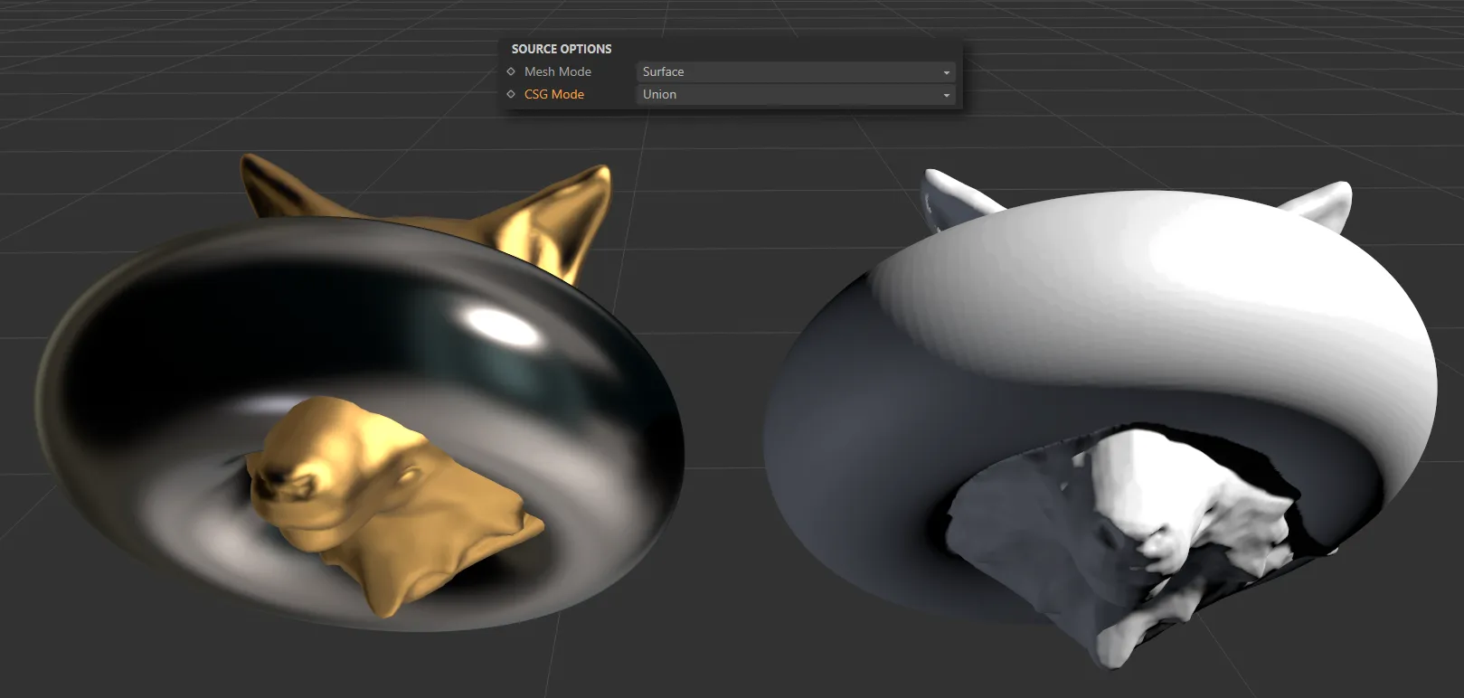
This mesh has a CSG Mode of Union.
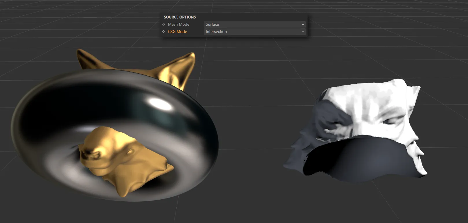
Here, the CSG Mode is Intersection, with only the intersected part being meshed.
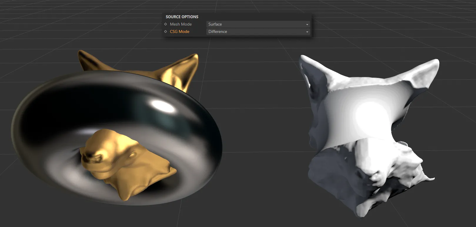
In the CSG Mode of Difference, only the areas of the Wolf which do not overlap with the Torus are meshed.
Volume mode
Section titled “Volume mode”The object is treated as a volume.
Value Threshold
Section titled “Value Threshold”This is used when meshing an NoneExplosiaFX object.
It is the value in the EFX object data that is considered to be valid data; values below this are not considered valid.
This can help to remove bad data coming from the EFX object.
ISO Value
Section titled “ISO Value”This is the value in the VDB voxels which is considered to be on the surface of the mesh.
Fill Interior Voxels
Section titled “Fill Interior Voxels”Enabling this will fill all the voxels inside the surface of the generated object.
This is mainly intended for use when meshing volumes.
Interior Band Voxels, Exterior Band Voxels
Section titled “Interior Band Voxels, Exterior Band Voxels”The interior and exterior band widths control how many voxels to fill inside and outside the volume respectively.
It is recommended that you do not change these settings from the defaults as increasing the exterior band width excessively will try to fill too many voxels with fog data than Cinema 4D can handle and it may appear to freeze.
Link Voxel Size to Main Generator
Section titled “Link Voxel Size to Main Generator”If this is enabled and the object is an Explosia FX object, the voxel size will be set to the same as the voxel size in the Explosia FX object.
Voxel Size
Section titled “Voxel Size”This setting is only available if Link Voxel Size To Main Generator is disabled; then you can set the voxel size independently of the source object.
Half Width
Section titled “Half Width”Most of the time you can leave this unchanged.
It alters the width of the narrow band of active (surface) voxels so, if it is lowered, you may see a slightly better definition to the mesh; this is usually marginal at best.
If you make it too small, some voxels which should be in the narrow band are omitted and you will start to see holes and artefacts in the mesh.
This menu enables you to select which Explosia data field to use for the meshing.
The three options are Smoke (the default), Fuel and Heat.
CSG Mode, Generate Object ID, Mesh Adaptivity
Section titled “CSG Mode, Generate Object ID, Mesh Adaptivity”Identical to the settings in Points mode.
Point Options
Section titled “Point Options”These settings are only effective if the Mesh Mode for a polygon object is set to Points or if the source object is a spline, a null object or an X-Particles emitter.
They have no effect on any objects if the object’s Mesh Mode is set to Surface.
Point Radius
Section titled “Point Radius”This controls the size of the spheres generated around each point or particle.
Min Point Radius, Max Point Radius
Section titled “Min Point Radius, Max Point Radius”These are the limits on the size of the virtual sphere generated around each particle by the mesher.
If the sphere size is outside these limits, it will not be included in the mesh.
For the most part you can leave the default values as they are, but if you need to exclude very small or very large particles, you can alter these limits.
Filters tab
Section titled “Filters tab”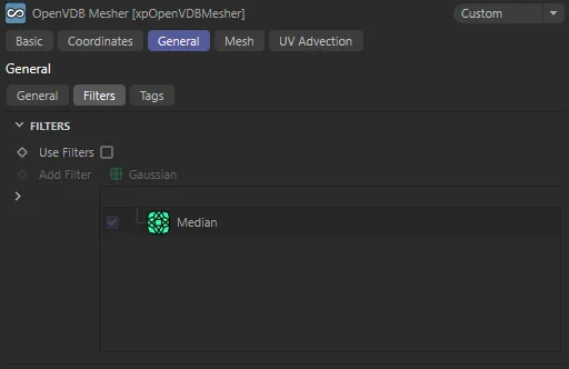
Filters tab settings.
Filters are smoothing routines which can be applied to the mesh.
You can apply as many filters as you like, but note that the order the filters are in may affect the final result.
These filters may have very significant effects on the mesh, altering both its size and shape.
There is one filter in the list by default, a simple Median filter.
You can delete or disable this if you wish.
Use Filters
Section titled “Use Filters”If this is unchecked, no filters are used even if there are some in the list.
Add Filter
Section titled “Add Filter”Select the desired filter from this drop-down menu.
The choices are: Gaussian, Laplacian, Mean, Curvature, Median and Offset.
To disable a filter temporarily, uncheck the box to the right of its name or right-click it and, from the context menu, click Disable.
Some, but not all, filters have a value that can be changed.
Click the filter to select it and a value field appears; you can then alter the values.
Not all values are available for all filters.
Generally, it is best to experiment with each filter to get an idea of how they affect the final result.

There are no filters applied to the mesh in this image.
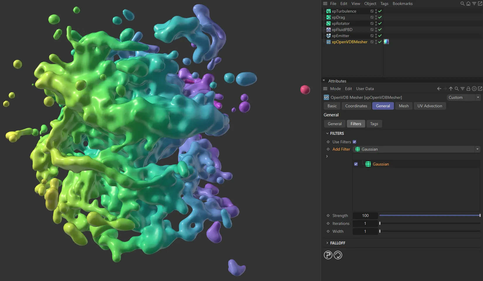
A Gaussian filter has been added here.

A Laplacian filter is applied, in this image.
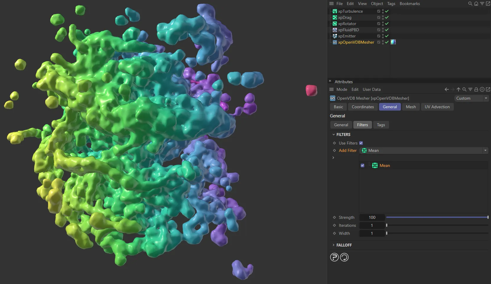
Here, a Mean filter is being applied.

With a Curvature filter added to the mesh.
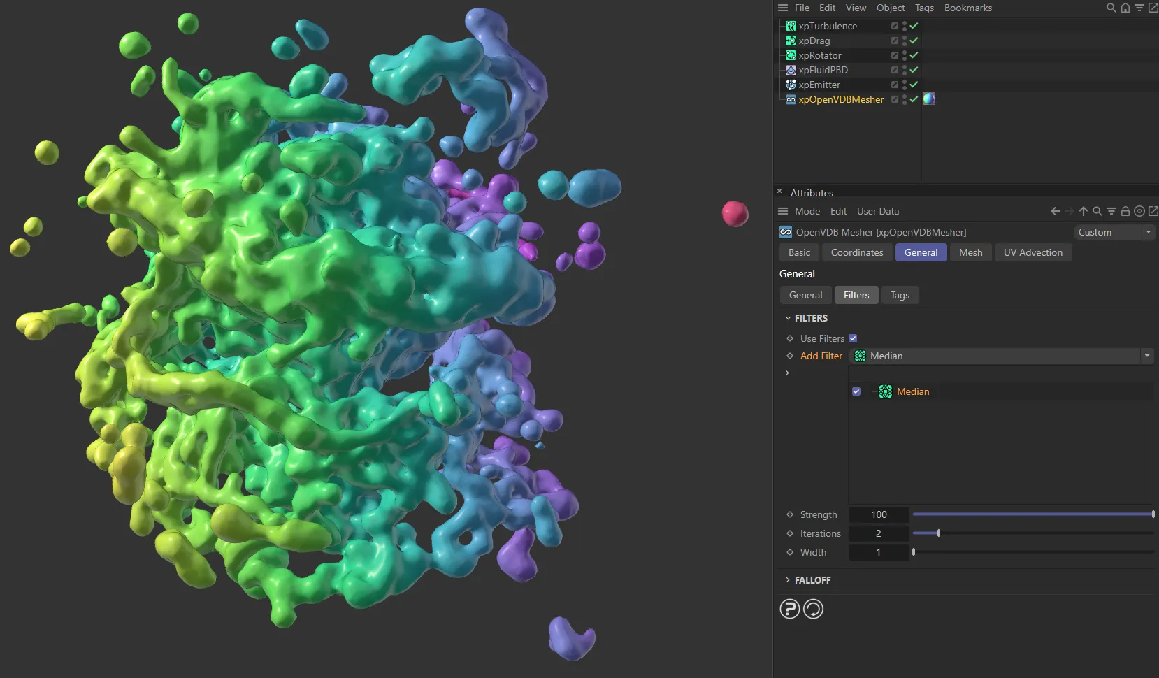
In this image, a Median filter is being applied.
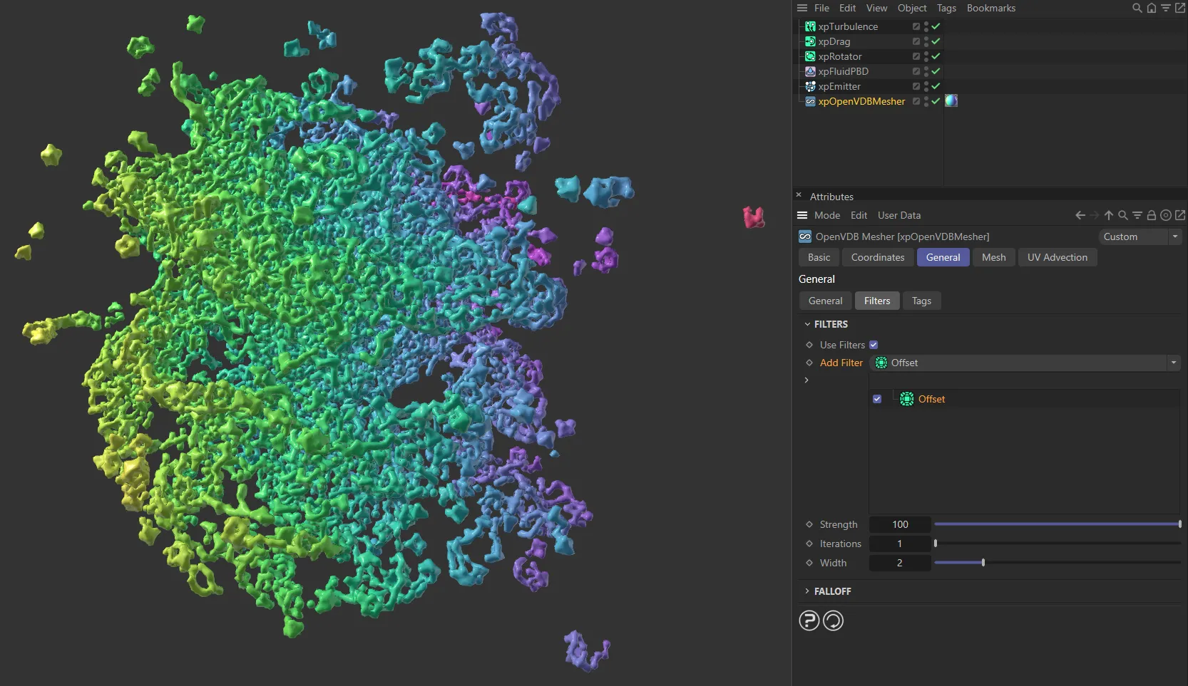
The filter here is an Offset, giving a very different look.
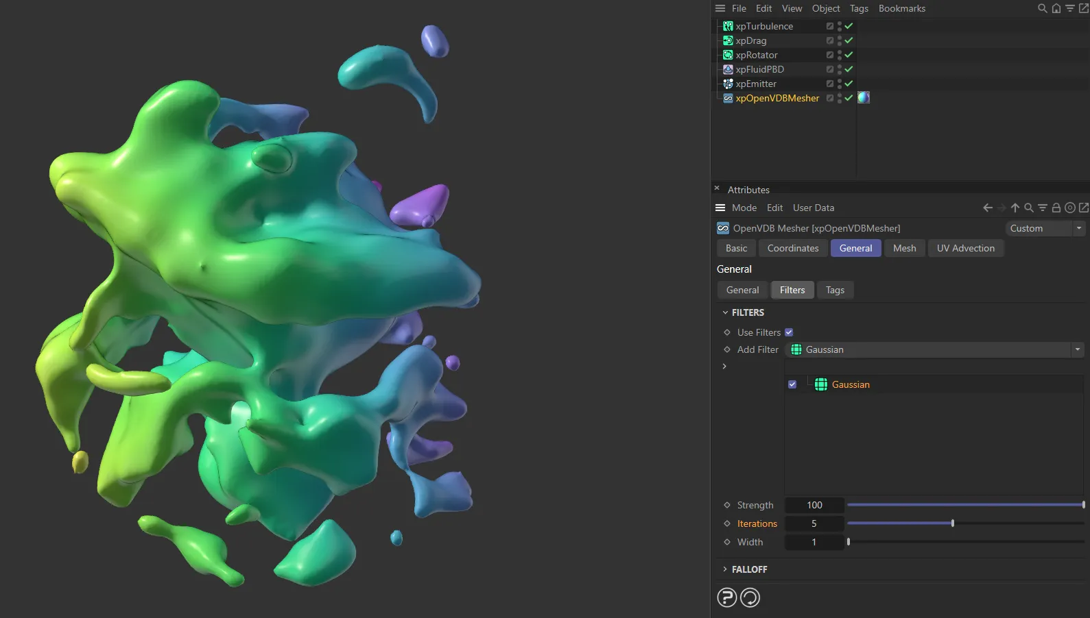
Finally, you can see the Gaussian filter, once again, with Iterations increased to 5.
Falloff
Section titled “Falloff”This option gives you precise location and falloff-based masking, by using one of the following fields: Box, Capsule, Cone, Cylinder, Formula, Group, Linear, Python, Radial, Random, Shader, Sound, Spherical and Torus.
There are also XParticles options of: xpNoiseFalloff, xpParticlesFalloff and xpShaderFalloff, which can all be selected here.
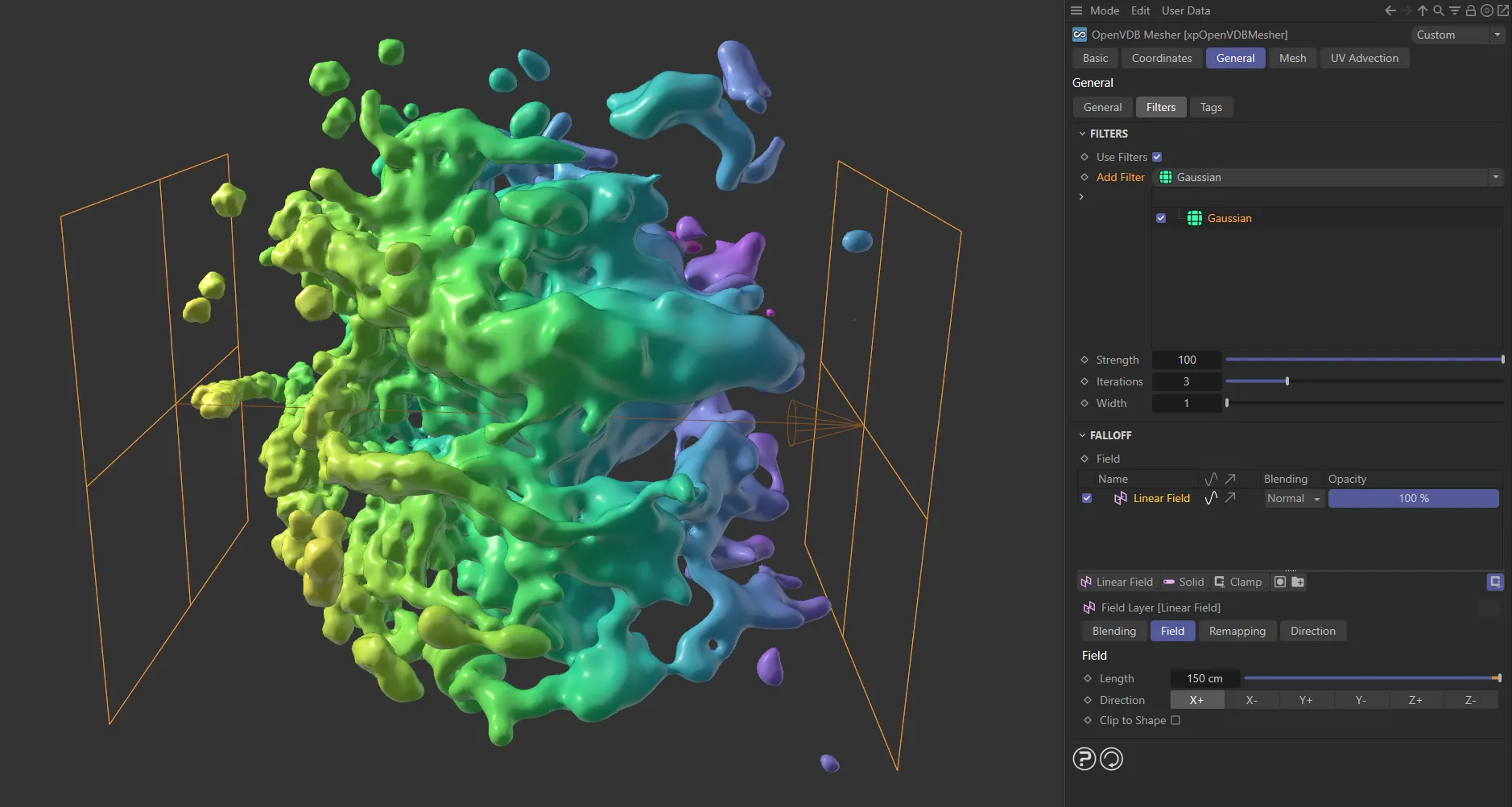
In this image, a Linear Field is driving the meshing, achieving an effect of increased Gaussian filtering, with no filtering on the left and the full amount on the right.
Tags tab
Section titled “Tags tab”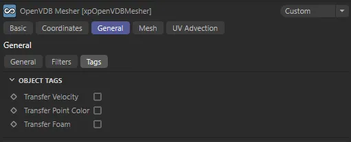
Tags tab settings.
Transfer Velocity
Section titled “Transfer Velocity”If you enable this, further options become available.
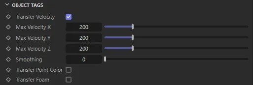
Additional Transfer Velocity parameters.
These tags contain color information for each vertex in the object, derived from the vertex velocity.
These can be used to render a velocity map, which can then be used in compositing to produce motion blur.
Max Velocity X, Y, Z
Section titled “Max Velocity X, Y, Z”This is the velocity which sets the relevant color component to maximum (the default setting of 200 units gives 100% of that color component).
Velocity Map Soothing Iterations
Section titled “Velocity Map Soothing Iterations”The velocity map can be smoothed to a greater extent by increasing this value.
Transfer Point Color
Section titled “Transfer Point Color”When this is enabled, a Vertex Color tag is generated on the mesher which contains the color from the particles.
This can be used in a Vertex Map shader to render the mesh with the particle colors.
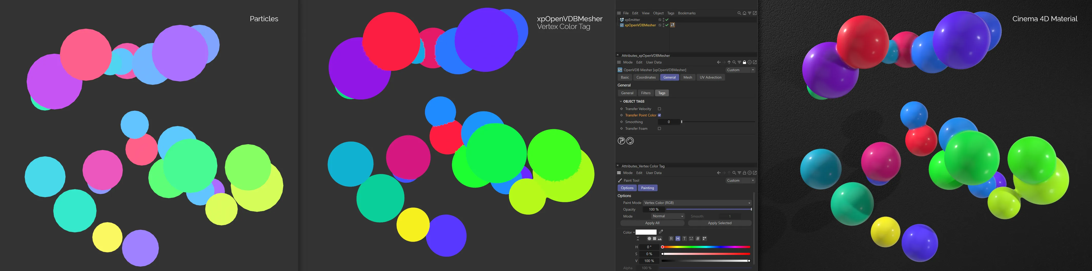
On the left, you can see xpEmitter particles. In the center, with Transfer Point Color enabled, the Vertex Color tag, generated by xpOpenVDBMesher is recording the particle colors. On the right, a Cinema 4D material, with the generated Vertex Color tag in a Vertex Map effect in the Texture channel, has been applied to the xpOpenVDBMesher generated mesh.
The following additional parameter will become available when this option is enabled.
Smoothing
Section titled “Smoothing”The color map can be smoothed to a greater extent by increasing this value.
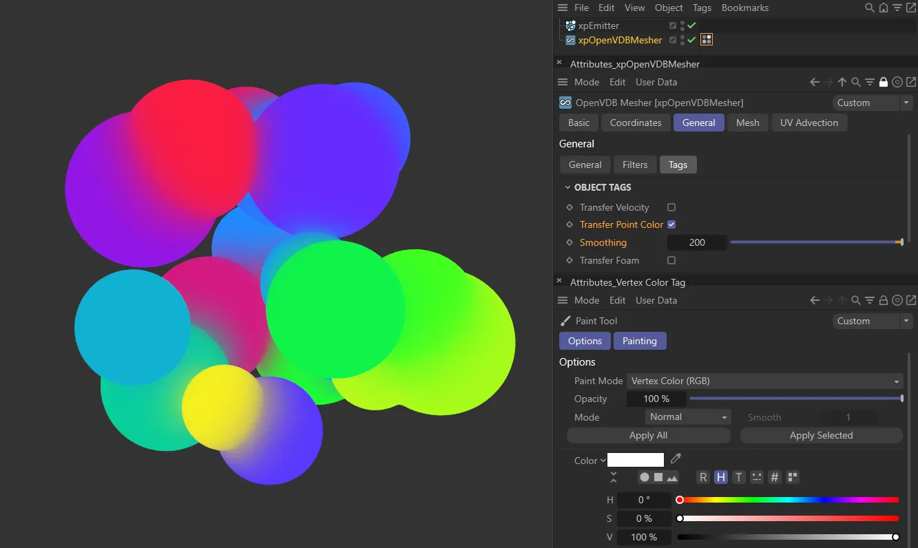
The Smoothing value is set at 80 here, evidenced where the particles meet.
Transfer Foam
Section titled “Transfer Foam”Enabling Transfer Foam creates a vertex map, reading data from the xpFoam dynamic modifier.
This setting is only available when Mode is set to Mesh.
The data from xpFoam is used to generate a vertex map on the surface of the mesh.
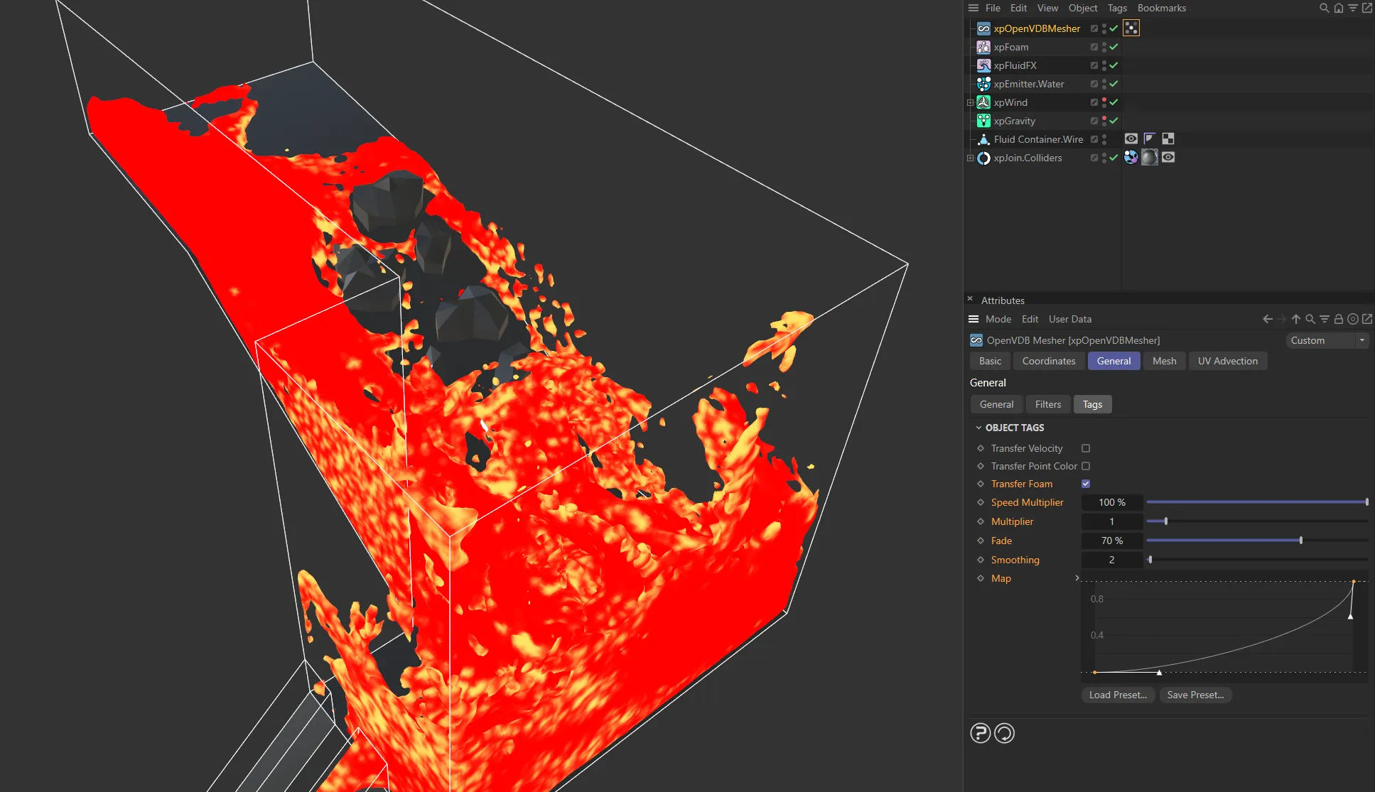
Here, with Transfer Foam enabled, the Vertex Map tag is reading data from xpFoam and generating bright areas where the foam would exist.
Mesh tab
Section titled “Mesh tab”These are options used to control the nature of the generated mesh.
The parameters available are dependent on the Mode setting in the General tab.
Mesh mode options
Section titled “Mesh mode options”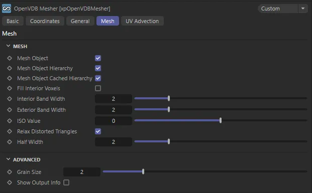
Mesh tab settings in Mesh mode.
Mesh Object
Section titled “Mesh Object”The actual object in the Sources list will be meshed if this is enabled.
Turn this off to avoid unwanted mesh when meshing a null object with a child object.
If it is left on, and Mesh Mode is set to Points, unwanted geometry will be produced at the position of the null object.
Mesh Object Hierarchy
Section titled “Mesh Object Hierarchy”Leave this enabled to mesh child objects of the object in the Sources list.
Mesh Object Cached Hierarchy
Section titled “Mesh Object Cached Hierarchy”When meshing an object with a cached hierarchy, this must be enabled.
Such objects would include any generator object which produces its output from one or more child objects (the MoGraph Cloner is a good example of this).
If this box is unchecked, but Mesh Object Hierarchy is enabled, only the actual child object(s) of the Cloner will be meshed and not the output of the Cloner.
Generally, you can always leave this checked, and there are no problems if the object does not have a cached output.
But if you have an object with a cached output and you don’t want to mesh the cache, uncheck this box.
Fill Interior Voxels
Section titled “Fill Interior Voxels”Enabling this will fill all the voxels inside the surface of the generated object.
This is mainly intended for use when meshing volumes.
Interior Band Width, Exterior Band Width
Section titled “Interior Band Width, Exterior Band Width”The interior and exterior band widths control how many voxels to fill inside and outside the volume respectively.
It is recommended that you do not change these settings from the defaults as increasing the exterior band width excessively will try to fill too many voxels with fog data than Cinema 4D can handle and it may appear to freeze.
ISO Value
Section titled “ISO Value”This is the value in the VDB voxels which is considered to be on the surface of the mesh.
Relax Distorted Triangles
Section titled “Relax Distorted Triangles”Enabling this will relax any triangles that might be distorted due to mesh adaptivity.
Half Width
Section titled “Half Width”Most of the time you can leave this unchanged.
It alters the width of the narrow band of active (surface) voxels so, if it is lowered, you may see a slightly better definition to the mesh; this is usually marginal at best.
If you make it too small, some voxels which should be in the narrow band are omitted and you will start to see holes and artefacts in the mesh.
Spheres mode options
Section titled “Spheres mode options”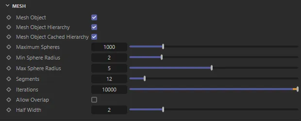
Mesh tab settings in Spheres mode.
Additional parameters particular to Spheres mode:
Maximum Spheres
Section titled “Maximum Spheres”This is the maximum number of spheres that will be created, even if there is space to include more.
Min Sphere Radius, Max Sphere Radius
Section titled “Min Sphere Radius, Max Sphere Radius”Sets the size limits of the spheres.
If they are both the same the spheres will be of uniform size.
Segments
Section titled “Segments”The segment count for the generated spheres.
Iterations
Section titled “Iterations”This is the number of points in the volume the mesher will look at to place a sphere.
The higher this value, the greater the chance of being able to place a sphere but the mesher will take longer to complete the result.
Allow Overlap
Section titled “Allow Overlap”If this is enabled, the spheres will be allowed to overlap.
This produces a cleaner fit of the spheres but the spheres may (will) overlap one another.
ExplosiaFX mode options
Section titled “ExplosiaFX mode options”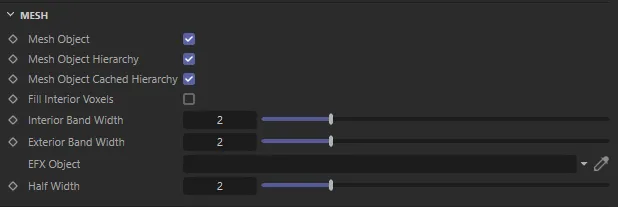
Mesh tab settings in ExplosiaFX mode.
Additional parameter particular to ExplosiaFX mode:
EFX Object
Section titled “EFX Object”Drag and drop an ExplosiaFX object into this field, to generate the mesh.
Fog mode options
Section titled “Fog mode options”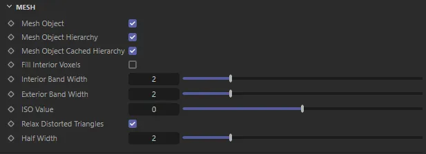
Mesh tab settings in Fog mode.
There are no additional parameters particular to the Fog mode.
Voxels mode options
Section titled “Voxels mode options”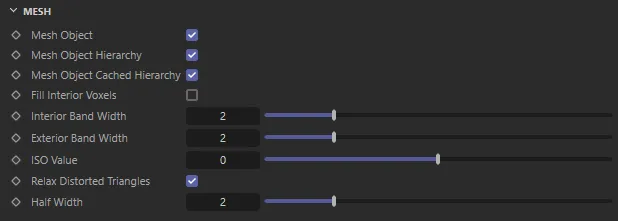
Mesh tab settings in Voxels mode.
There are no additional parameters particular to the Voxels mode.
Advanced
Section titled “Advanced”Grain Size
Section titled “Grain Size”If set to higher than 0 (zero), the mesher is threaded.
For most use-cases this can be left on the default 2.
Show Output Info
Section titled “Show Output Info”If this is enabled, then information about the generated object will be displayed.
What is shown depends on the Mode setting.
UV Advection tab
Section titled “UV Advection tab”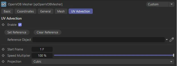
UV Advection tab settings.
In this tab, you can apply UV advection to your mesh.
Enable
Section titled “Enable”Check this box to enable UV Advection.
Reference Object
Section titled “Reference Object”Drop the object, that you want to apply the UV advection to, into this field.
Set Reference, Clear Reference
Section titled “Set Reference, Clear Reference”You can set a reference point at any point in your simulation, creating a reference object, using Set Reference.
Clear Reference will clear this reference object from the scene.
Animation to demonstrate the effect of the UV Advection settings.
Start Frame
Section titled “Start Frame”Sets the frame when you want UV Advection to begin.
You are able to set the reference at the same Start Frame number to get a smooth transition into the beginning of UV Advection.
Speed Multiplier
Section titled “Speed Multiplier”This setting speeds up or slows down the advection of motion to the UV.
A lower value slows down the movement, a higher value will make the movement appear faster.
Projection
Section titled “Projection”Set as Cubic, by default, with all the usual UV projection modes available.
The alternative settings are: Spherical, Cylindrical, Flat, Frontal, Spacial, UVW Mapping, Shrink Wrapping and Camera Mapping.
Copyright © 2026 INSYDIUM LTD. All rights reserved.