xpElektrix
xpElektrix creates ‘lightning bolt’ style effects.
Unlike other X-Particles objects, it can be used with or without a particle emitter.
General tab
Section titled “General tab”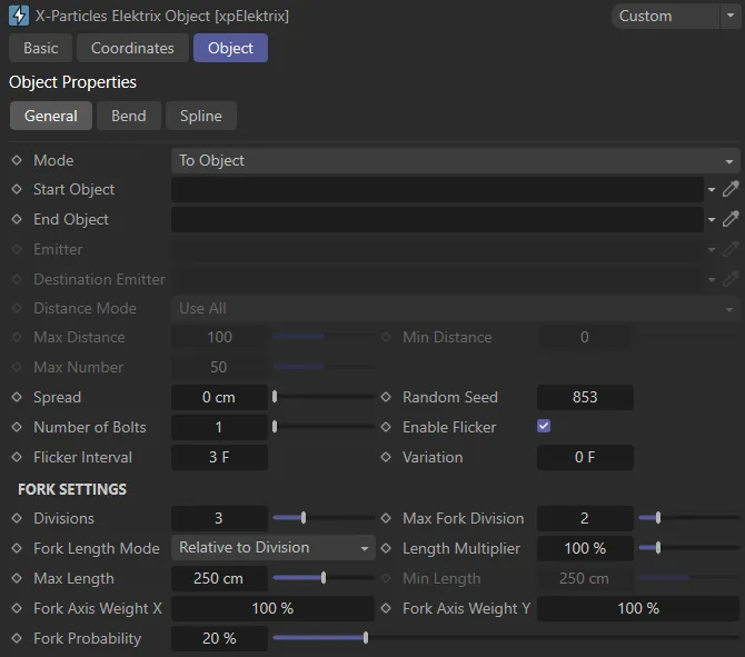
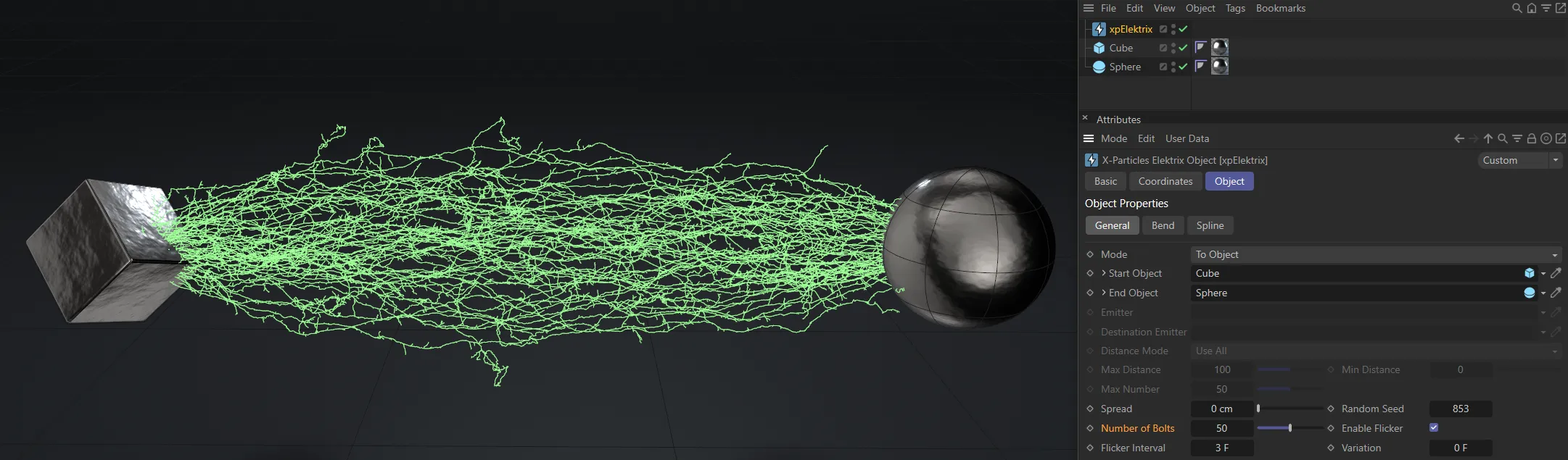
xpElektrix General tab settings.
Set as To Object, by default, xpElektrix has four modes of operation.
The alternatives are: Spherical, To Particles and Particle to Particle.
To Object mode
Section titled “To Object mode”With this mode, you do not need a particle emitter.
Instead the bolt is drawn between two objects.
These can be any object, including lights or null objects.
The bolt is drawn from the axis position of the Start Object to the axis position of the End Object.
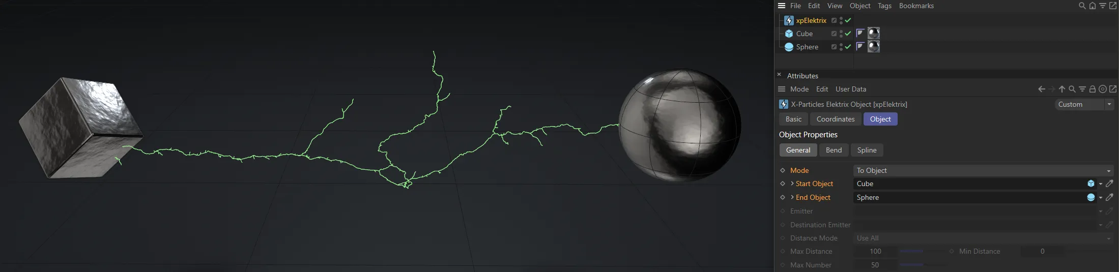
Here the Mode is To Object, with the Cube and Sphere connected via their origin points.
Spherical mode
Section titled “Spherical mode”Again, this does not require an emitter.
The bolt is drawn from the Start Object axis position to a randomly-chosen position on an invisible sphere surrounding the Start Object.
The length of the bolt is governed by the Bolt Length and Variation settings.
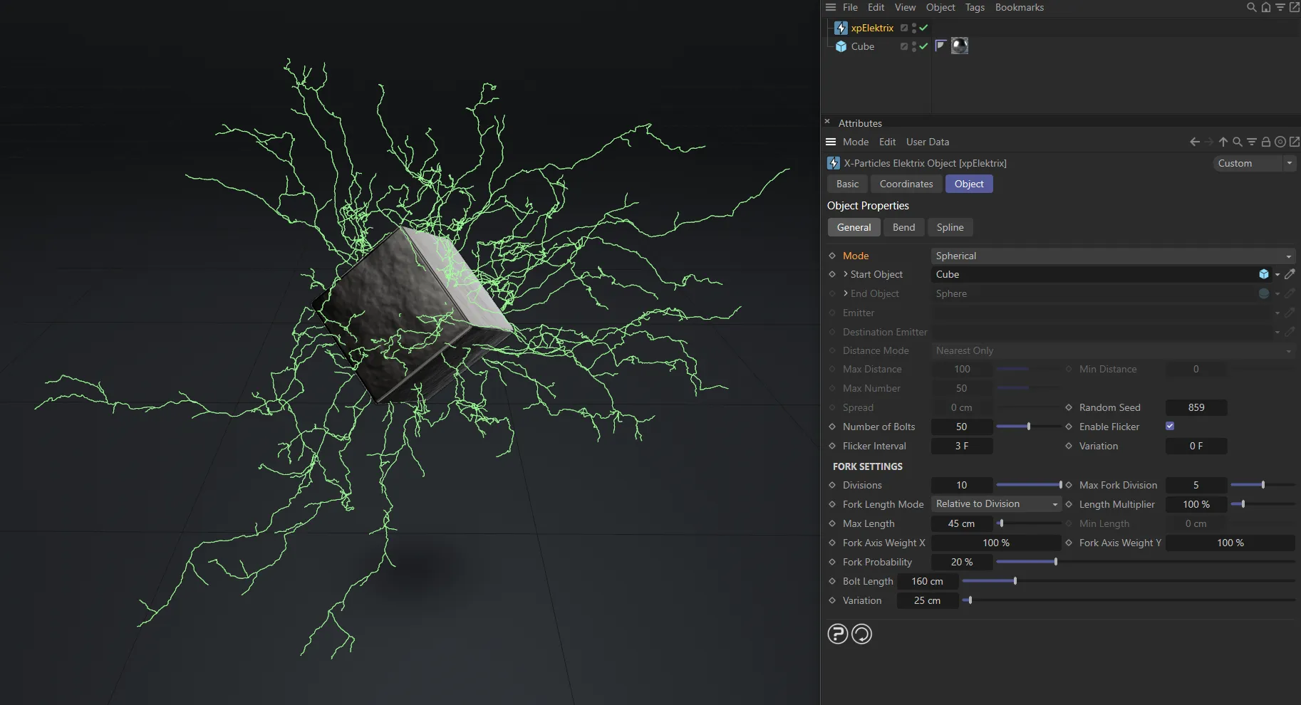
The Mode is now Spherical; the electrical splines draw from the center of the Start Object and grow outwards, spherically.
To Particles mode
Section titled “To Particles mode”In this mode a bolt is drawn from the the Start Object axis position to each particle emitted from an emitter.
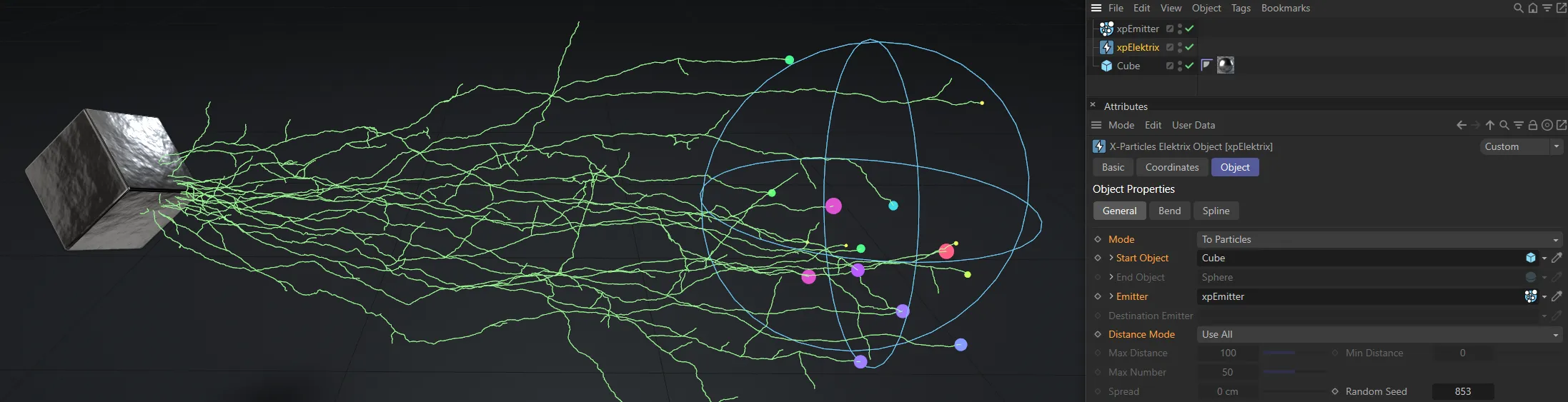
In this image, the Mode is To Particles, with splines from the Cube to all particles in the linked emitter.
Particle to Particle mode
Section titled “Particle to Particle mode”Here, bolts are drawn from particles in the Emitter to the corresponding particle in the Destination Emitter.
Meaning that bolts are drawn between particle 1 in the first emitter to particle 1 in the second, and so on.
It is your responsibility to make sure that the destination emitter has enough particles to match those emitted from the first emitter.
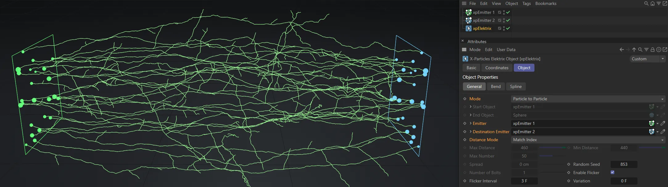
The final Mode setting is shown here, Particle to Particle.
Start Object
Section titled “Start Object”The object the bolt originates from in all but Particle To Particle mode.
Drag the object to be used into this field.
End Object
Section titled “End Object”The object the bolt ends at in To Object mode.
Drag the object to be used into this field.
Emitter
Section titled “Emitter”The source emitter used in To Particle and Particle To Particle modes.
Drag an X-Particles emitter into this field.
Destination Emitter
Section titled “Destination Emitter”The emitter providing the ‘destination’ particles in Particle To Particle mode.
Drag an X-Particles emitter into this field.
Distance Mode
Section titled “Distance Mode”Set to Use All, by default, this drop-down menu is only used when Mode is set to To Particles or Particle to Particle.
The alternative settings are: Nearest Only, All Within Distance and Max Number Within Distance.
Use All
Section titled “Use All”Bolts will be drawn to all particles.
Nearest Only
Section titled “Nearest Only”A bolt will only be drawn to the nearest particle.
Here, with the Mode set as To Particles and the Distance Mode of Nearest Only, the spline is only drawn to the particle closest to it.
All Within Distance
Section titled “All Within Distance”Bolts will be drawn to all particles whose distance is between the values in Max Distance and Min Distance.
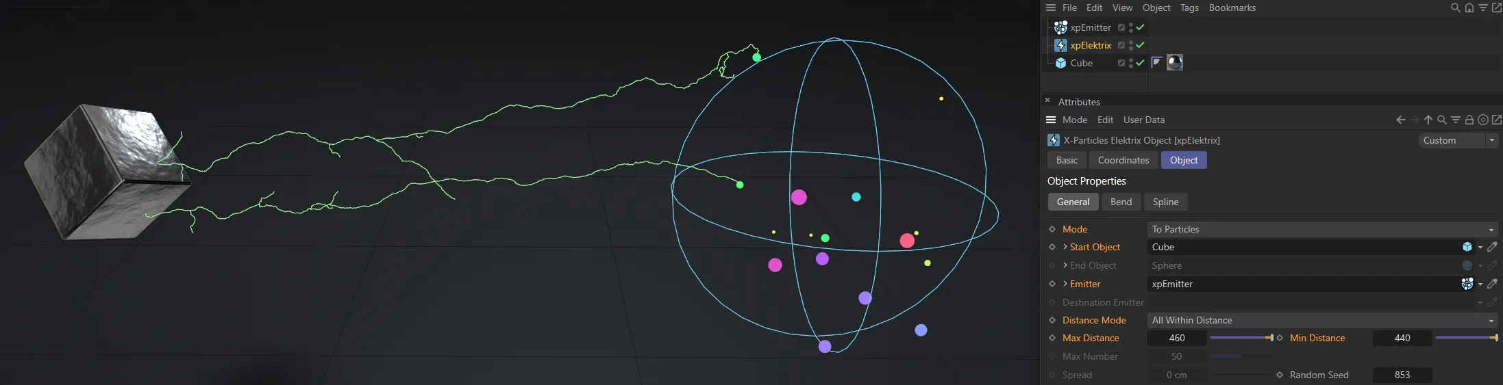
With the Distance Mode as All Within Distance and distances set between 440 and 460, all particles within this 20cm range are viable connection points.
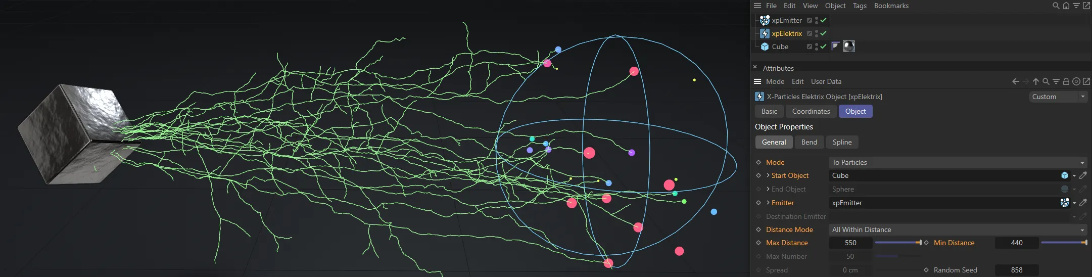
In this second image, the Max Distance is increased to 550, displaying more connections than before but there are still no connections to particles outside of the 110cm range.
Max Number Within Distance
Section titled “Max Number Within Distance”This is the same as All Within Distance but the number of bolts is limited to the value in Max Number.
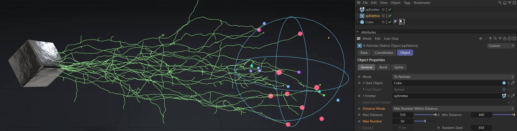
Here, the Distance Mode is Max Number Within Distance, with Max Number set to 50, limiting the connections to 50.
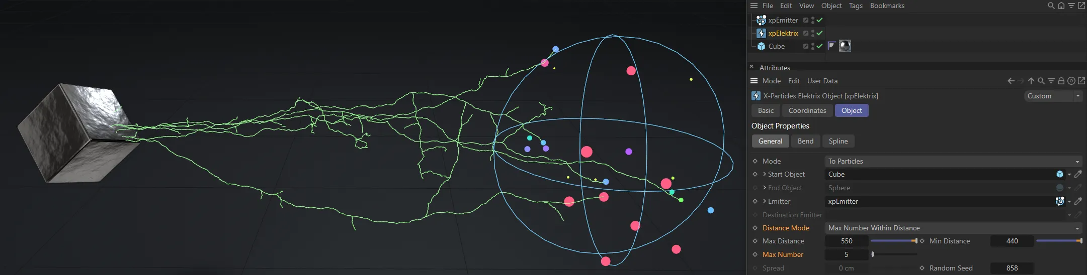
In this second image, Max Number has been reduced to 5, restricting the connections to 5 only.
Max Distance
Section titled “Max Distance”This is the farthest away a particle can be from an object or a particle for a bolt to form when Distance Mode is set to All Within Distance or Max Number Within Distance.
Min Distance
Section titled “Min Distance”This is the closest a particle can be to an object or a particle for a bolt to form when Distance Mode is set to All Within Distance or Max Number Within Distance.
Max Number
Section titled “Max Number”When Mode is set to Max Number Within Distance, this is the maximum number of bolts which can form.
Spread
Section titled “Spread”This is only used in To Object mode.
If it is set to zero, the end position of all the bolts will be at the axis position of the End Object.
Increasing this value will randomly spread the end position around the axis position of the End Object, within this distance value.
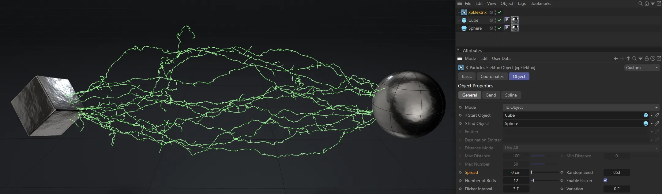
Spread value of 0 (zero) cm, resulting with connections at the origin point of the End Object.
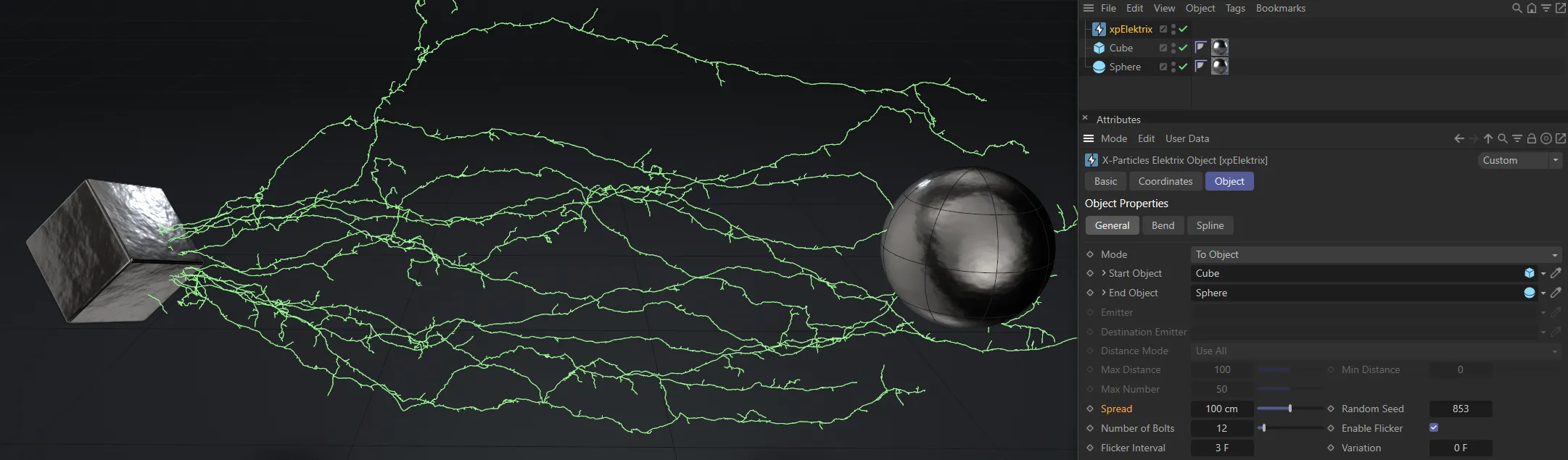
With Spread raised to 100cm, the end points of the connections are pushed away from the origin point.
Random Seed
Section titled “Random Seed”This is the seed used when generating the bolts.
If you don’t like the result, try changing this value.
Number of Bolts
Section titled “Number of Bolts”Only used in To Object and Spherical modes, as in the other modes, the number of bolts is determined by the number of particles.
It controls the number of bolts which are generated.
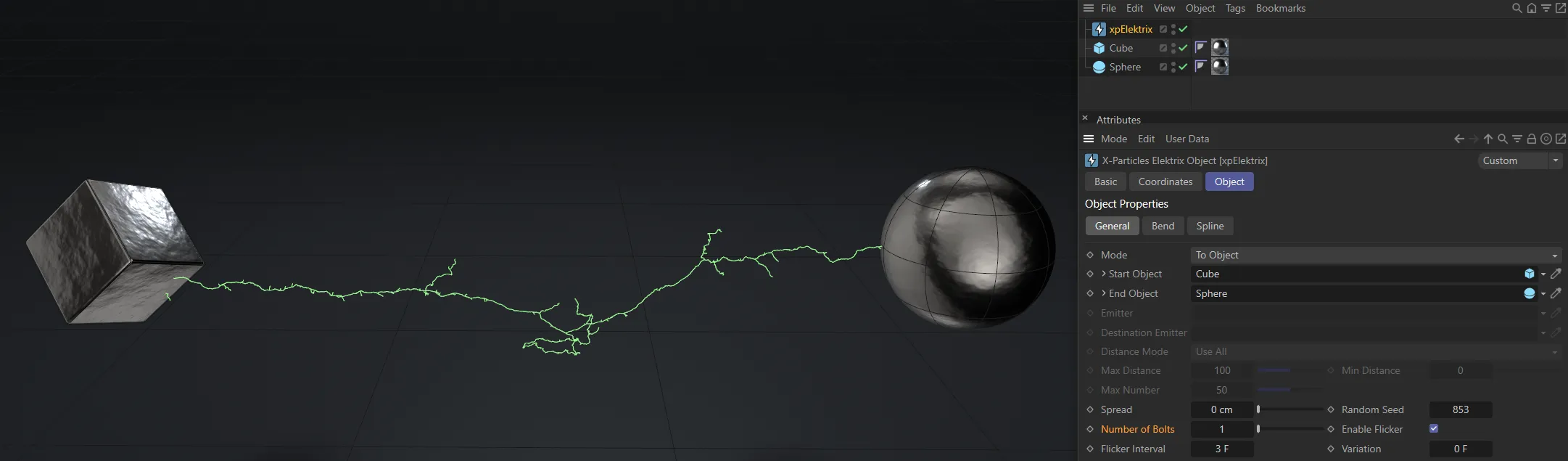
Number of Bolts set as 1.
Here, the Number of Bolts has been increased to 50.
Enable Flicker
Section titled “Enable Flicker”If enabled, each bolt will randomly flick to another shape at intervals determined by the Flicker Interval setting.
If you don’t want this to happen, untick this box.
Flicker Interval, Variation
Section titled “Flicker Interval, Variation”The time between shape changes in each bolt.
Variation can be added with the Variation setting to prevent too regular a result.
Only available if Enable Flicker is ticked.
With Enable Flicker checked, Flicker Interval is keyframed, from 5 frames down to 1, in this animation.
In this second animation, the Flicker Interval and the Variation are both set at 8 frames.
Fork Settings
Section titled “Fork Settings”Divisions
Section titled “Divisions”This controls the subdivision of the bolt.
A value of zero simply generates a straight line between the two points.
When set to 1, the bolt will be divided in two somewhere along its length, causing a bend in the bolt.
Increasing the count to 2 will divide each half of the bolt in two again.
Each time the number of divisions increases, the number of segments in the bolt is doubled.
The bolt will remain the same general overall shape, but the detail will increase significantly.
A value of 4 - 6 is fine for most purposes.
At high division levels, and with many bolts, this can result in a lot of points.
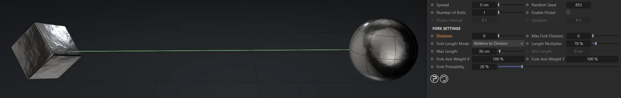
Divisions set at 0 (zero).

Divisions now set at 1.
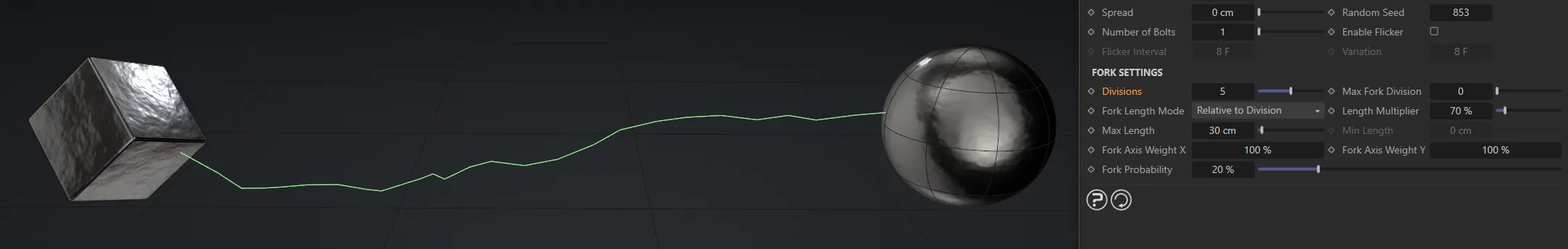
Here, the Divisions value is 5
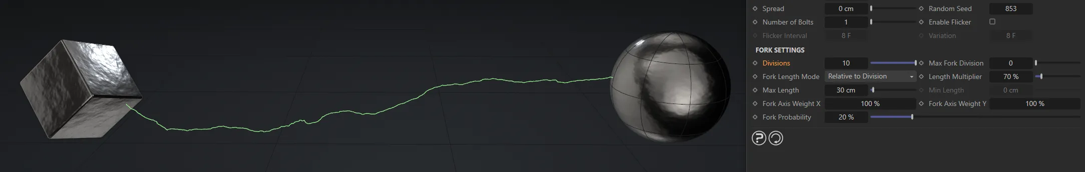
Finally, the fork is divided further, with Divisions set at 10.
Max Fork Division
Section titled “Max Fork Division”As well as dividing the bolt segments in two at each division, the object can also produce forks or branches from the point of division.
If you have 6 divisions you may end up with a lot of little forks, so this setting halts forking at the level of division in this setting.
A value of 3 is usually sufficient.
A value of zero will prevent all forking.
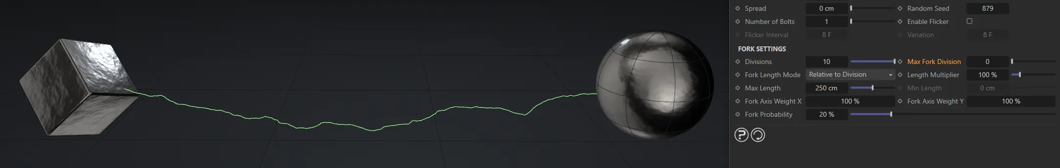
Max Fork Division of 0 (zero).
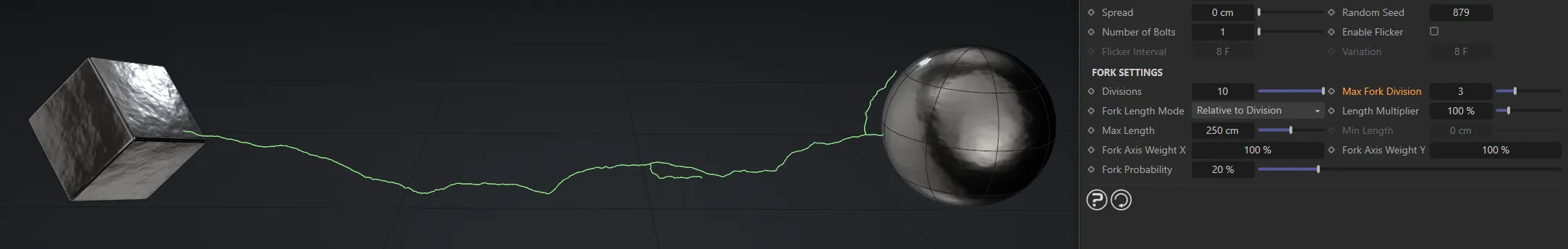
Here, the Max Fork Division is set at 1.
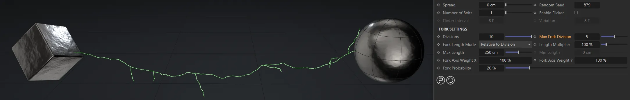
The Max Fork Division is raised to 5, in this image.
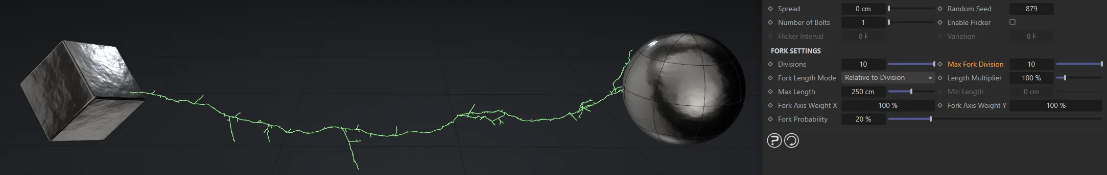
Max Fork Division of 10.
Fork Length Mode
Section titled “Fork Length Mode”Set as Relative to Division, by default, this setting refers to the length of any forks in the bolt, not the length of the bolt itself.
The default is that when a fork is generated, it is the length of the distance between the point it is generated from and the next point in the spline.
As the bolt proceeds through the number of iterations (divisions) in the object, the distance between spline points gets shorter and shorter.
The result is a few long forks and a larger number of small forks.
The alternative mode is that the fork has an absolute length in scene units.
Relative to Division
Section titled “Relative to Division”This is the default mode where the fork length depends on the division level at which it is generated.
Absolute
Section titled “Absolute”The alternative mode, in which the length is an absolute value in scene units.
In this mode, all the forks have a variable length between a maximum and minimum value.
Length Multiplier
Section titled “Length Multiplier”Regardless of length mode, this value is used to multiply the fork length.
All forks will then show a uniform increase or decrease in length.
Max Length
Section titled “Max Length”In Relative to Division mode, this setting ensures that the fork length never exceeds this value.
If the fork length is lower than this value, it is unaffected.
In Absolute mode, this is the upper limit of the length of the fork and is used in conjunction with the Min Length setting to determine the actual length.
Min Length
Section titled “Min Length”Used only in Absolute mode, this is the lower limit of the length of the fork.
It is used together with the Max Length setting.
Fork Axis Weight X, Fork Axis Weight Y
Section titled “Fork Axis Weight X, Fork Axis Weight Y”When the fork is generated, it deviates from its parent along the X and Y axes local to the object.
If both values are set to 100%, the fork may deviate away at any angle.
If you set the Y value (for example) to 0 (zero) %, the fork will only deviate along the local X axis.
For the most part, these values can be left at the default of 100% for a truly random deviation.
Fork Probability
Section titled “Fork Probability”This the probability that a fork will occur at a division point.
You can alter the value here to increase or reduce the chance of forking.
Generally, smaller numbers produce better results.
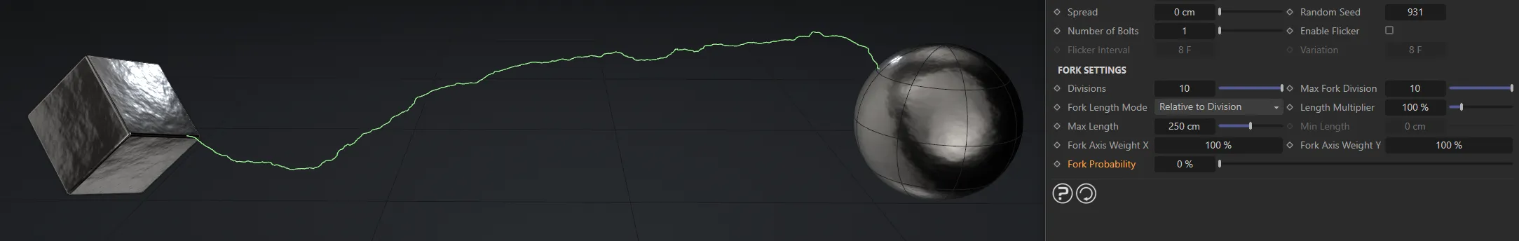
Fork Probability set at 0 (zero).
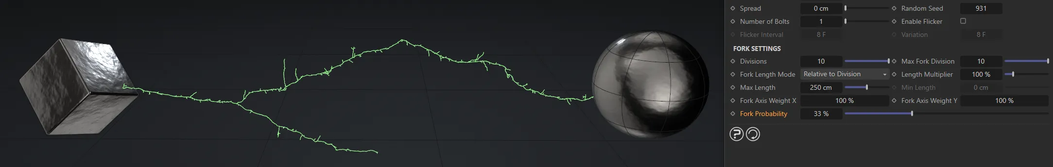
The Fork Probability raised to 33%.
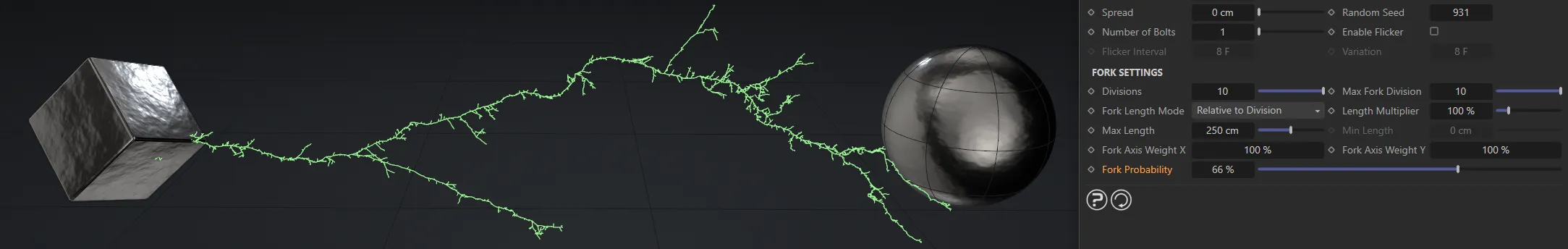
Here, the Fork Probability is 66%.
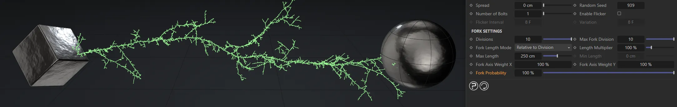
Finally, a Fork Probability at 100%.
Bolt Length, Variation
Section titled “Bolt Length, Variation”These two settings are only available in Spherical mode and control the length of the bolt.
Variation can be added to the length with the Variation setting.
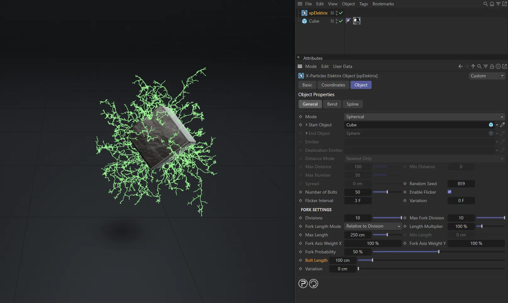
Bolt Length set at 100cm.
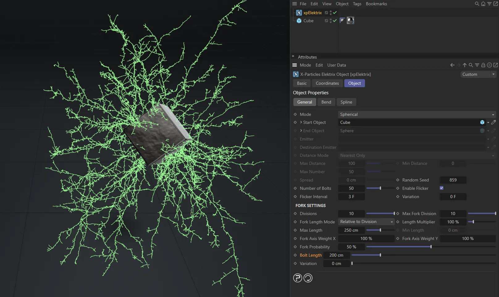
Bolt Length raised to 200cm.
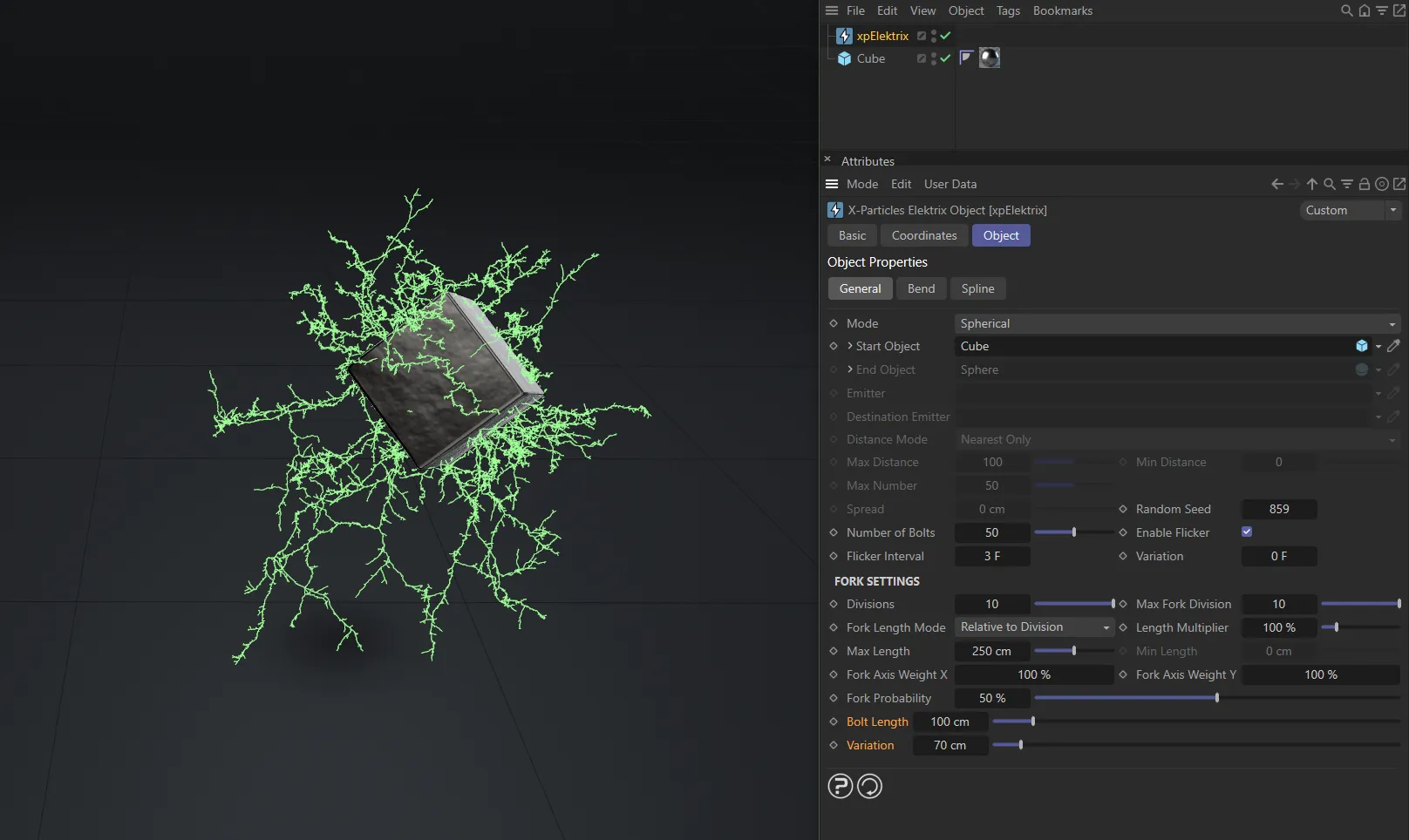
Here, the Bolt Length is 100cm, with a Variation of 70cm.
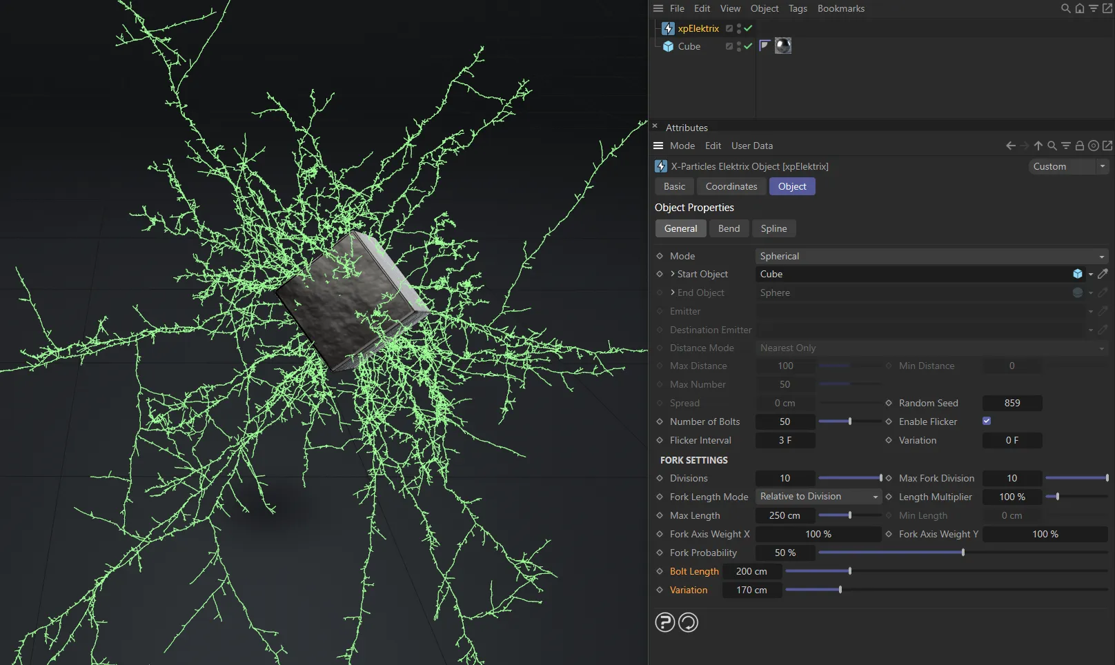
In this image, the Bolt Length is 200cm, with a Variation of 170cm.
Bend tab
Section titled “Bend tab”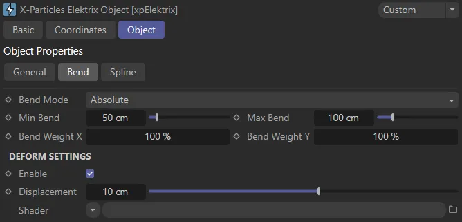
xpElektrix Bend tab settings.
Bend Mode
Section titled “Bend Mode”Set as Absolute, by default, this drop-down controls the amount of deviation of each point in the bolt; it controls the amount of ‘bending’ at each division point.
The alternate setting is Proportionate to Length.
Absolute
Section titled “Absolute”The amount of deviation is an absolute value in scene units.
Proportionate to Length
Section titled “Proportionate to Length”In this mode, the amount of deviation is a proportion of the bolt length.
The reason for this is that if the bolt length is small, the amount of deviation in Absolute mode may be very disproportionate to the bolt length.
This mode will adjust the deviation according to the length of the bolt, ensuring a more consistent appearance if the bolt length changes, for example in either of the particle modes.
Min Bend, Max Bend
Section titled “Min Bend, Max Bend”The amount of deviation or bending at each division point.
These are either in scene units (Absolute mode) or as a percentage of the bolt length (Proportionate to Length mode).
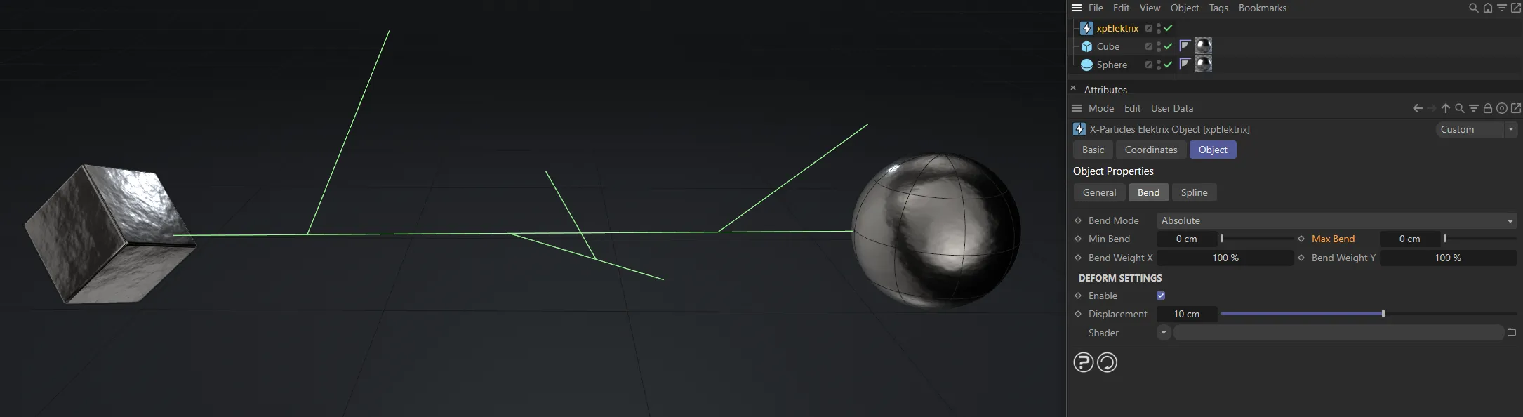
The Min Bend and Max Bend are both 0 (zero) cm here.
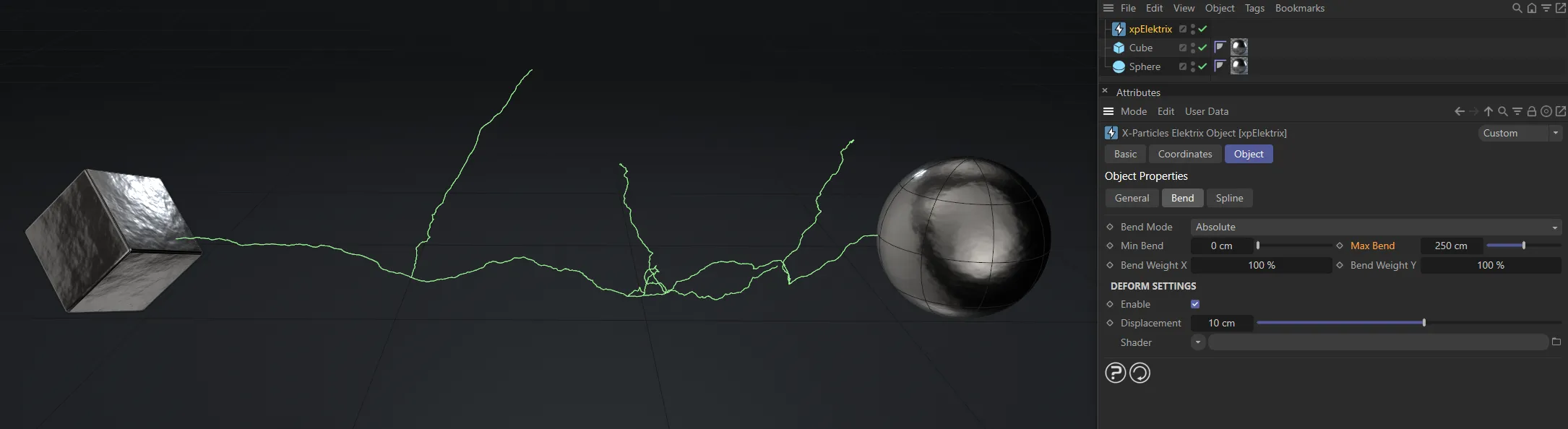
Max Bend, only, raised to 250cm.
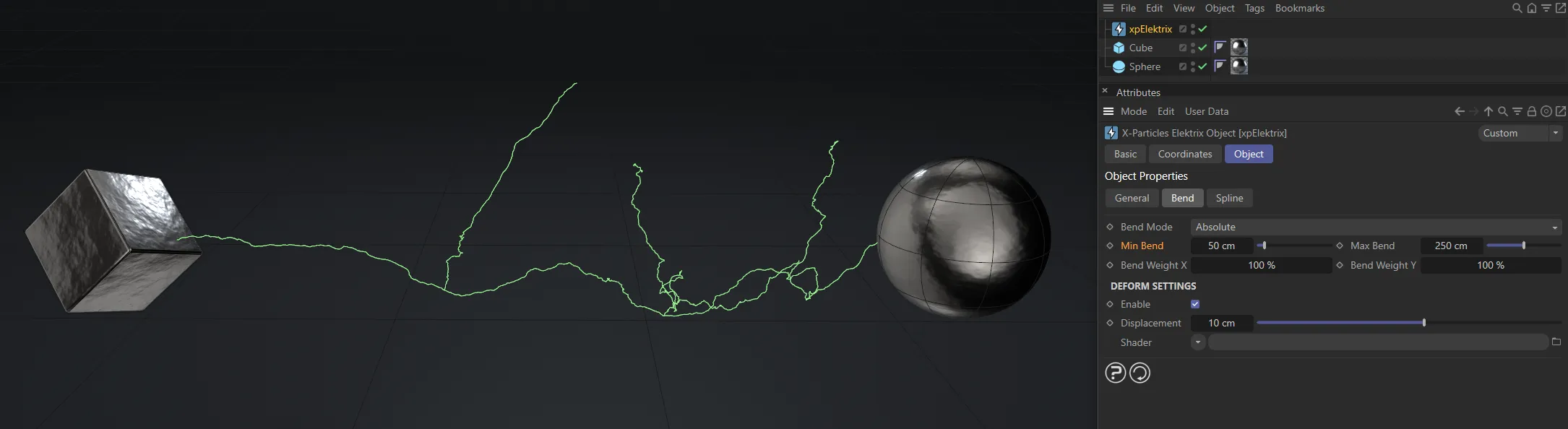
Here, the Max Bend remains at 250, while the Min Bend is now 50cm, ensuring a minimum bend amount throughout.

In this fourth image, the Min Bend is now increased to 150cm.
Bend Weight X, Bend Weight Y
Section titled “Bend Weight X, Bend Weight Y”When the fork deviates from its parent, it does so along the X and Y axes local to the object.
If both of these values are set to 100%, the fork may deviate away at any angle.
If you set the Y value (for example) to 0 (zero) %, the fork will only deviate along the local X axis.
For the most part, these values can be left at the default of 100%, for a truly random deviation.
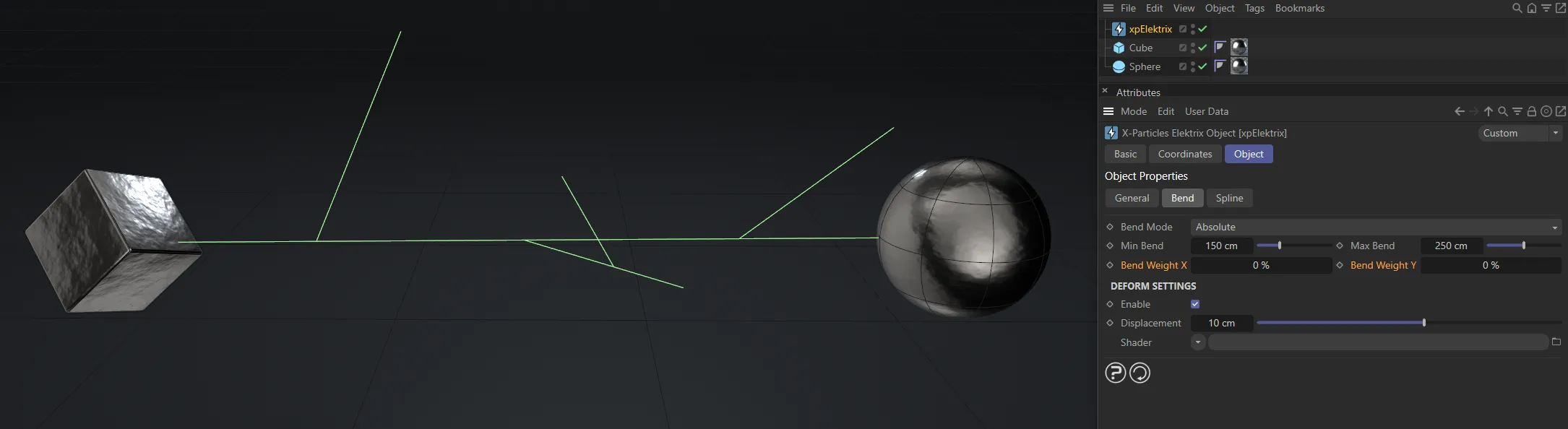
Bend Weight X and Bend Weight Y both set at 0 (zero) %.
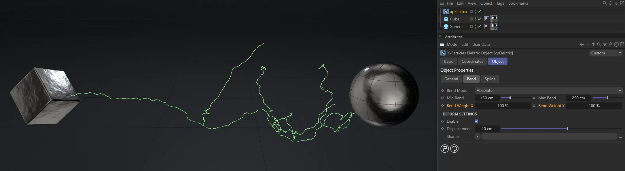
In this image, there is a full amount (100%) of bend weight on both axes.
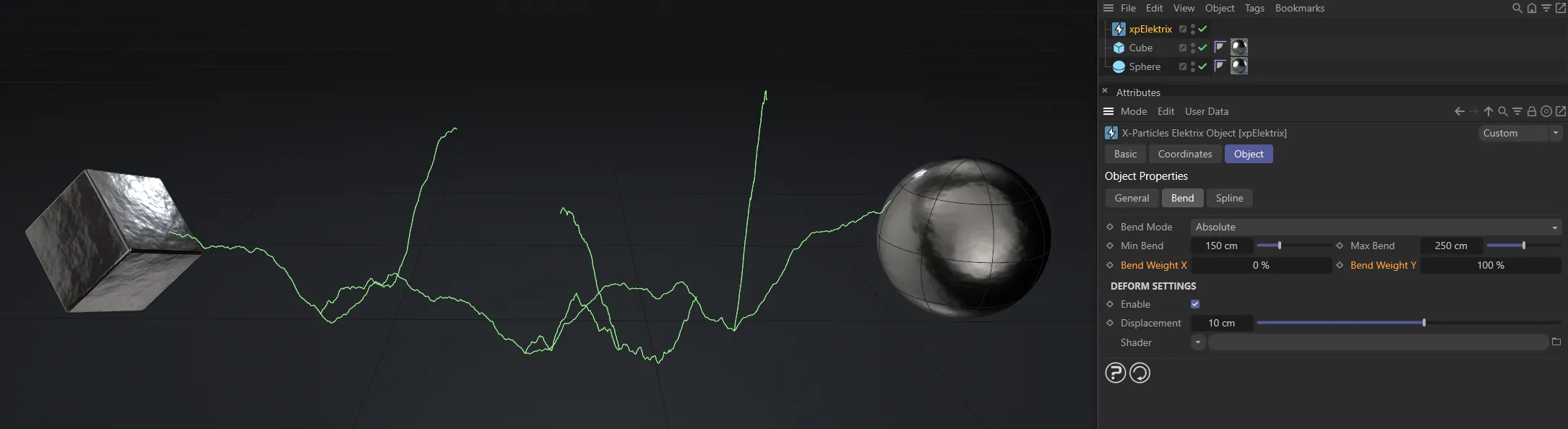
The Bend Weight X remains at 0 (zero)%, here, while the Bend Weight Y is at 100%.
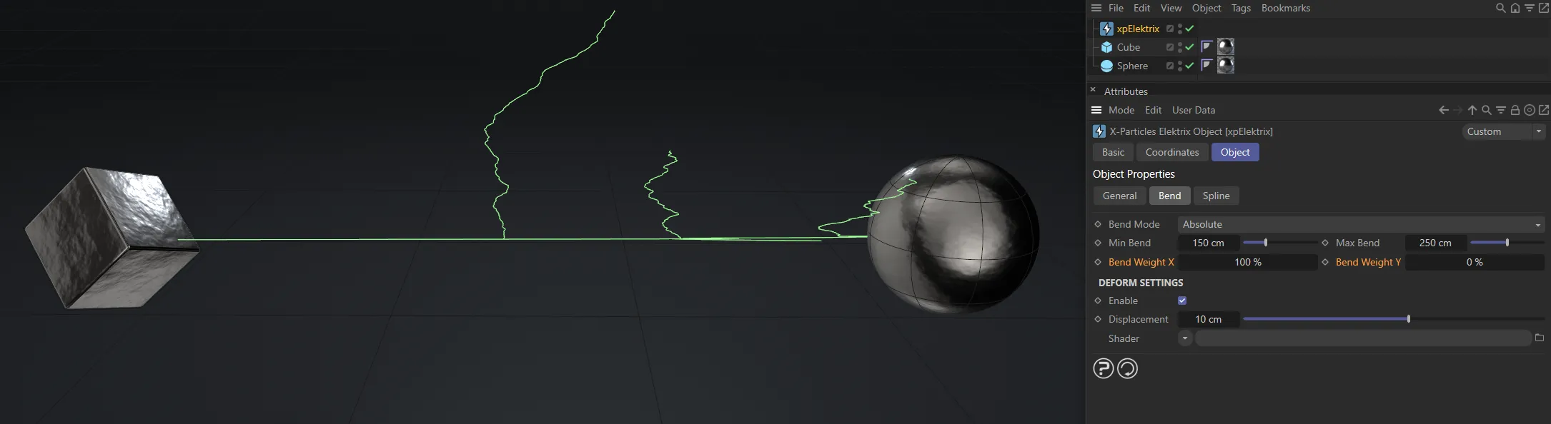
Finally, the opposite of the previous image, with 100% set on Bend Weight X and Bend Weight Y is now back at 0 (zero) %.
Deform Settings
Section titled “Deform Settings”These settings allow you to add additional deformation to the bolt with a shader.
Best results are obtained with an animated Noise shader, but any shader can be used.
Enable
Section titled “Enable”If ticked, the shader will deform the bolt.
Displacement
Section titled “Displacement”This is the ‘strength’ of the deformation.
Larger values will result in larger deformation.
If it is too large, you may see artefacts, such as forks, becoming detached from their parent branch.
Shader
Section titled “Shader”Add a shader to this link field.
A Noise shader is recommended as this can be animated and produce interesting effects.
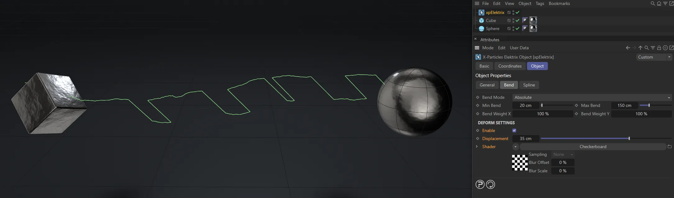
In this image, a Checkerboard shader has been applied.
Spline tab
Section titled “Spline tab”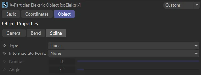
xpElektrix Spline tab settings.
Set as Linear, by default, this is a subset of the usual spline settings seen in Cinema 4D.
The alternative types are: Cubic, Akima, B-Spline and Bezier.
Intermediate Points
Section titled “Intermediate Points”Set as None, by default.
The alternative settings are: Natural, Uniform, Adaptive and Subdivided.
Number
Section titled “Number”In Natural and Uniform modes, use this field to set the number of intermediate points.
In Adaptive and Subdivided modes, use this Angle threshold setting to control the generation of intermediate points on curved edges.
Copyright © 2026 INSYDIUM LTD. All rights reserved.