xpDisplayRender
With xpDisplayRender you can render the particles, field vectors and bounds as they appear in the viewport.
This is a generator object which takes each particle (or field vector) and constructs renderable geometry from it.
In the case of the field vectors, most particle shapes and the collider bounds, the generated object is a spline and you can render it using the X-Particles material.
In a few cases, the object is a polygon object and you should use the X-Particles Object Shader in a channel material.
Object Properties
Section titled “Object Properties”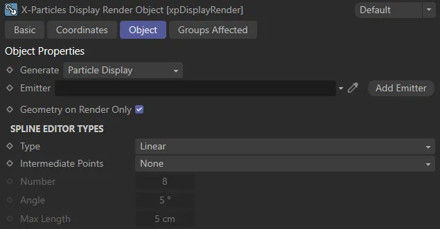
xpDisplayRender Object tab settings.
Generate
Section titled “Generate”Set to Particle Display, by default, this drop-down menu selects which type of object will be rendered.
The alternative options are: Flowfield Display, Modifier Field, Collider Bounds, ExplosiaFX Velocity and FLIP Velocity.
Particle Display object
Section titled “Particle Display object”The particle shapes are rendered.
You will need to supply an emitter in the Emitter link field.
Most shapes are rendered as splines but some are polygon objects.
The shapes rendered as polygon objects are: Squares, Spheres, Arrows (Filled), Box (Filled), Circle (Filled) and Plane (Filled).
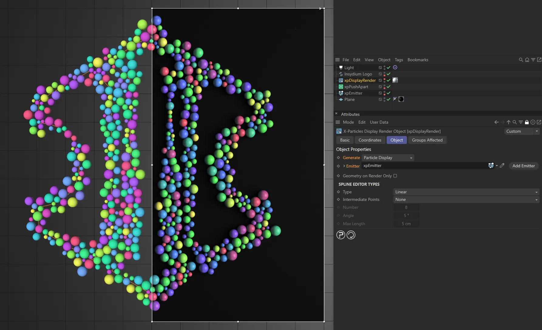
This image shows the live viewport on the left. The particles have been set as Spheres in the Display tab of the xpEmitter and are being born on the logo spline, then pushed apart with an xpPushApart modifier. The xpDisplayRender has Generateset to Particle Display and, with xpEmitter dropped into the Emitter field, is then linked to that emitter. On the right, there is an interactive render region, showing the resulting render, including the particles, generated by the xpDisplayRender. This has a Cinema 4D material applied, with the INSYDIUM xpObjectShader shader loaded into the Color channel, allowing the original particle colors to be seen.
Flowfield Display object
Section titled “Flowfield Display object”FlowField vectors are rendered as splines.
You will need to supply a FlowField object in the FlowField link field.
If you select this option, the interface changes slightly, to include the following parameters.
Flowfield
Section titled “Flowfield”A link field for a FlowField object.
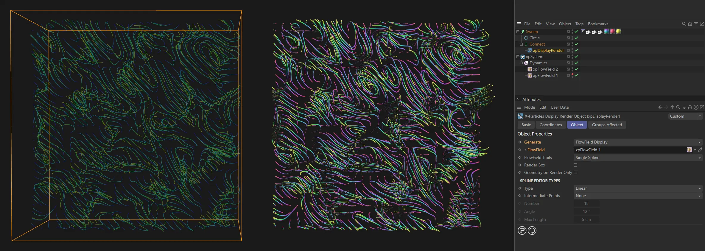
On the left, is the xpFlowField display, visualizing the Random layer’s vectors. On the right, the xpDisplayRender has Generate set to FlowField Display and is linked to the xpFlowField. This is inside of a sweep object, allowing the conversion of the generated splines into tube-like renderable geometry.
Flowfield Trails
Section titled “Flowfield Trails”Set as Single Spline, by default, it controls how splines are generated from the trails.
The alternative setting is Segmented Spline.
Single Spline
Section titled “Single Spline”Each trail results in a single spline being produced.
This gives a smaller number of objects, so is faster in the viewport and to render.
The disadvantage is that you lose the color information from the trail, but you can still color the trail with a gradient, if you use Cycles 4D.
Segmented Spline
Section titled “Segmented Spline”Each trail results in a number of separate splines each with its own color.
This preserves the trail color information so reproduces, on rendering, what you would see in the viewport.
The disadvantage is that the number of splines is greatly increased, so the viewport may slow down and the scene may take longer to render.
In general, the Single Spline mode is recommended, using a renderer such as Cycles 4D, or another engine which can render a spline with a color gradient along its length.
Segmented Spline is useful only if you wish to duplicate the same appearance of the viewport on rendering.
Modifier Field object
Section titled “Modifier Field object”Modifier field vectors are rendered as splines.
You will need to supply an emitter in the Emitter link field and, in the emitter’s Display tab, Modifier Field tab, enable the Show Field parameter.
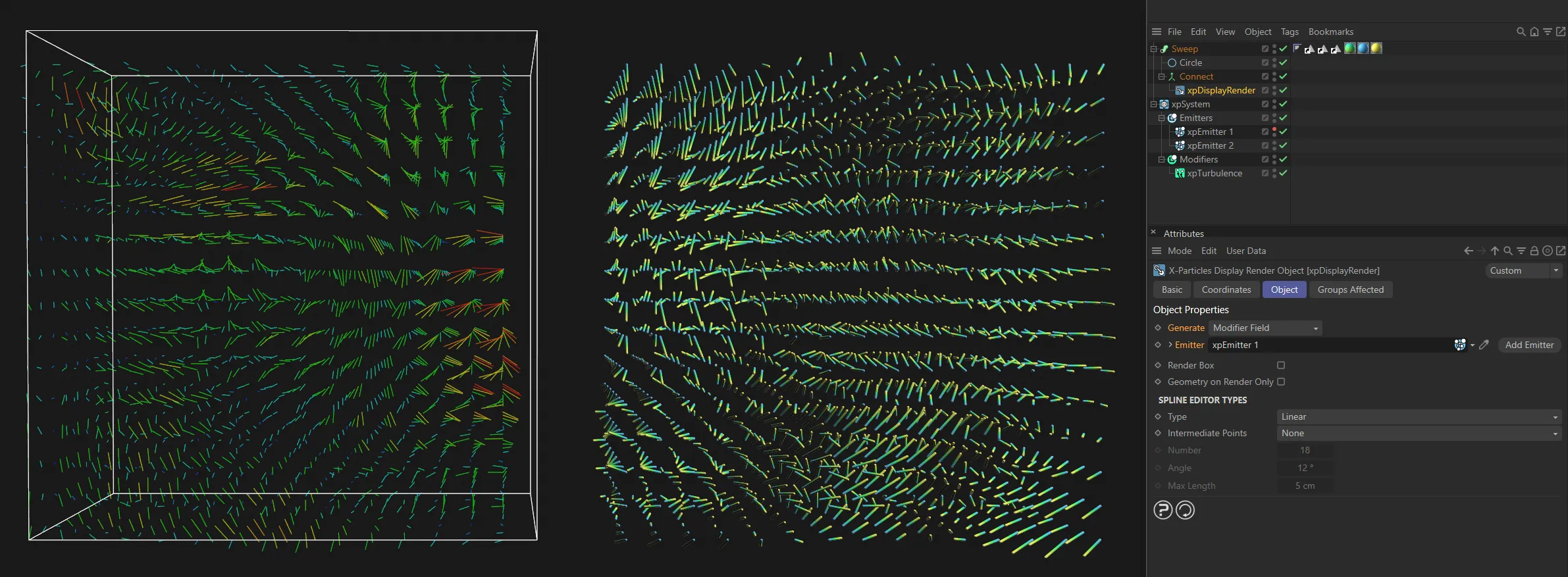
These settings are similar to the above, but this time with an xpTurbulence modifier. This process is viable by enabling the Show Field option in the Modifier Field tab from the xpEmitter’s Display tab. The Emitter is linked, once again from the Emitter field of xpDisplayRender, but it is the xpTurbulence vectors that are being displayed here.
Collider Bounds object
Section titled “Collider Bounds object”The collider bounds are rendered as splines.
You will need to add a Collider tag to the Collider Tag link field.
If you select this option, the interface changes slightly, to include the following three parameters.
Collider Tag
Section titled “Collider Tag”A link field for a Collider tag.
Color A, Color B
Section titled “Color A, Color B”The default colors for the collision boxes.
These are the same colors used in the collider tag for the viewport display, but you can change them for rendering purposes.
In this animation, on the left, is the live viewport result of a dynamic simulation, with Generate set to Collider Bounds. On the right is the resulting render, showing the Collider Bounds update, as the particles collide with the ‘floor’.
ExplosiaFX Velocity object
Section titled “ExplosiaFX Velocity object”This will render the velocity fields of an ExplosiaFX object as splines.
You will need to supply an ExplosiaFX object in the ExplosiaFX link field.
Regardless of what display you selected, this will render the velocity fields.
ExplosiaFX
Section titled “ExplosiaFX”A link field for an ExplosiaFX object.
FLIP Velocity object
Section titled “FLIP Velocity object”This will render the velocity fields from an xpFluidFLIP object.
To render these fields, you must enable the Velocity setting in the xpFluidFLIP Display tab.
When you select this option, the interface changes slightly, to include the following three parameters.
FLIP Fluid Object
Section titled “FLIP Fluid Object”A link field for a FluidFLIP object.
Set Min Segments
Section titled “Set Min Segments”The FLIP trails are drawn in the viewport as a minimum of eight short lines, each with a different color (this number may be higher if you have a long trail).
The purpose of this is to allow the trail to use colors from the Speed Color gradient in the xpFluidFLIP object so that trails appear to be multicolored along their length.
If this is disabled, a spline will be created for each of the lines drawn in the viewport.
This means that the trail will be rendered exactly as it appears in the viewport, but it also means that a large number of short splines will be generated, which is very slow.
If you check this box, you can set a fixed value for the number of splines per individual trail.
The minimum is one and this will result in a much faster render.
You could enable this setting if: you are doing a quick preview render; you are using a single-color gradient to color the trails, so you don’t need the larger number of segments; you are using Cycles 4D and will use a color ramp to color the trail so, again, you don’t need all the segments.
Min Segments
Section titled “Min Segments”The number of segments in the trail spline if Set Min Segments is enabled.
It is recommended that you don’t exceed the default value of 8 unless you really need to.
Emitter
Section titled “Emitter”A link field for an xpEmitter.
Not visible if Generate is set to FlowField Display or Collider Bounds.
Add Emitter
Section titled “Add Emitter”Click this button to create a new emitter and add it to the Emitter link field.
Not available if Generate is set to FlowField Display, Collider Bounds or ExplosiaFX Velocity.
Render Box
Section titled “Render Box”Some objects - the FlowField, the emitter’s Modifier Field display, ExplosiaFX Velocity and FLIP Velocity - have an enclosing box.
If this parameter is enabled, that box will also be rendered.
Geometry on Render Only
Section titled “Geometry on Render Only”Since you are reproducing in the render what is already visible in the viewport, there is no good reason to generate the spline or polygon objects in the viewport; that simply slows down Cinema 4D.
To prevent that, leave this parameter enabled.
If, for some reason, you really want to see the splines or polygon objects in the viewport, untick this box.
Spline Editor Types
Section titled “Spline Editor Types”Set to Linear, by default, these are the usual spline parameters seen in Cinema 4D.
The alternative types are: Cubic, Akima, B-Spline and Bezier.
Intermediate Points
Section titled “Intermediate Points”Set to None, by default.
The alternative settings are: Natural, Uniform, Adaptive and Subdivided.
Number
Section titled “Number”In Natural and Uniform modes, use this field to set the number of intermediate points.
In Adaptive and Subdivided modes, use this Angle threshold setting to control the generation of intermediate points on curved edges.
Max Length
Section titled “Max Length”In Subdivided mode, use this length threshold to limit the generation of intermediate points on straight edges.
Groups Affected tab
Section titled “Groups Affected tab”Groups
Section titled “Groups”To specify the group, drag and drop the desired Group object into this field.
This setting is useful if you want to ensure that the spawned particles are, or are not, affected by xpDisplayRender.
Copyright © 2026 INSYDIUM LTD. All rights reserved.