xpCellAuto
xpCellAuto simulates what are sometimes called ‘cellular automata’, creating self-sustaining particle growth systems.
Limiting the Y value of the xpCellAuto Solver Size results in a 2D style animation.
This second animation has a 3D application of xpCellAuto, using the Mode setting of Diffuse Limited Aggregation.
Usually, the emitter will emit a particle then call any available modifiers to act on it.
With this object, the emitter does not emit particles until forced to do so by the xpCellAuto object.
This happens outside the normal sequence so, if using an xpScale modifier (for example), the particle would first appear with the radius as set by the emitter and only in the next frame will this be changed by the modifier.
This issue applies not only to the particle radius but to any modifiers which alter parameters set by the emitter (e.g. color, mass, temperature, etc).
To avoid this, simply set the initial value in the emitter to match the value expected from the modifier and there won’t be a sudden change in the parameter.
More subframes would not normally benefit this object at all, since the particles are stationary.
But if you need them for other purposes, be aware that it will prevent the particle color mode Gradient (Parameter) from working correctly.
The particle will initially have the default particle color but, in the next frame, it will change to the color expected from the gradient according to the chosen parameter.
The solutions to this problem are either to choose another color mode or to reduce the subframes to the default of 1.
General tab
Section titled “General tab”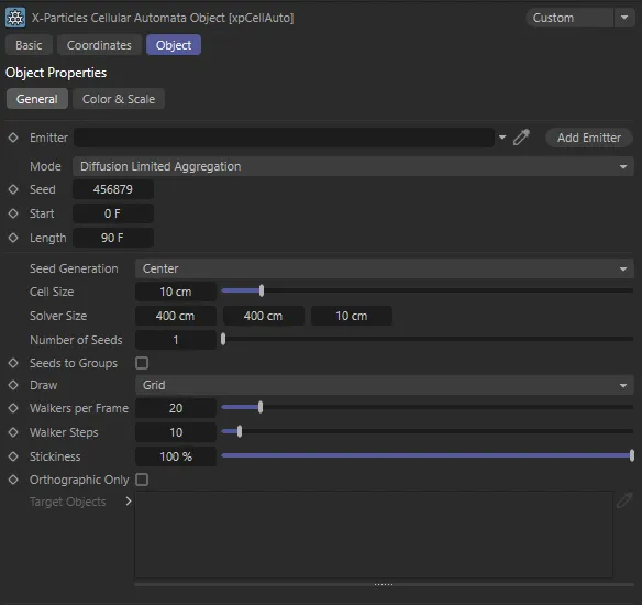
xpCellAuto General tab settings.
Emitter
Section titled “Emitter”This object needs an emitter to generate particles; drag an emitter into this field.
The emitter will automatically be switched into Controlled Only mode.
This means that particles will only be emitted when instructed by the xpCellAuto object.
You should not change this setting.
Add Emitter
Section titled “Add Emitter”Click this button to create a new emitter and add it to the Emitter link field.
Set as Diffusion Limited Aggregation, by default, with this drop-down menu you can choose the mode of operation.
The alternatives are: Elementary and Game of Life.
Diffusion Limited Aggregation
Section titled “Diffusion Limited Aggregation”This interesting mode is an example of simple diffusion-limited aggregation, in which particles stick together to form aggregates or clusters.
Animation to demonstrate the Mode set as Diffusion Limited Aggregation.
Elementary
Section titled “Elementary”This is the simplest mode and will generate a variety of two-dimensional patterns which vary by the rule chosen in the Rule No. field.
These are the classic 256 different rules for elementary cellular automata.
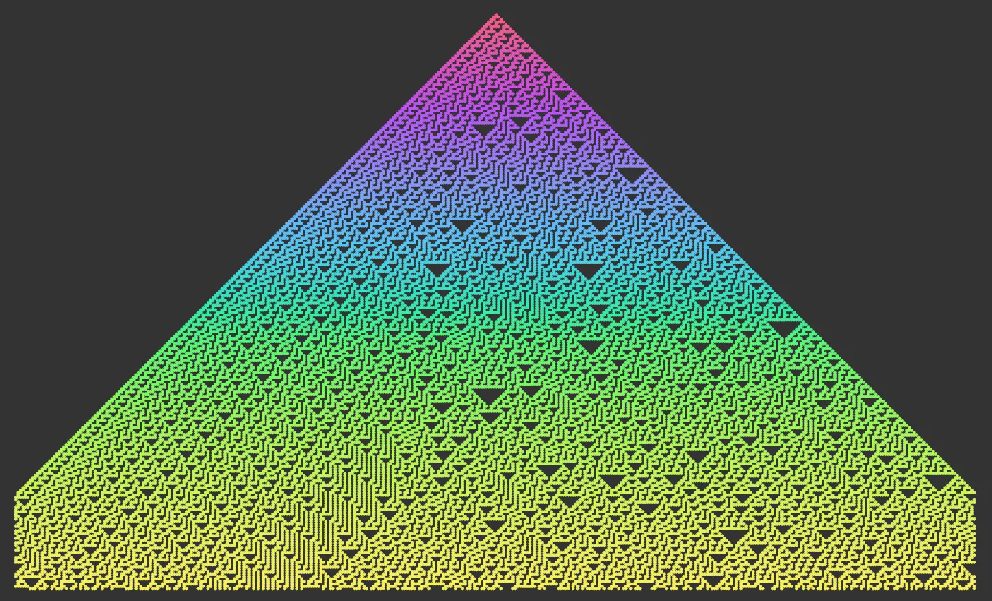
Rule 90 is the default, which produces the iconic Sierpinski triangle.
In this scene, the Mode is set to Elementary.
Game of Life
Section titled “Game of Life”This mode implements Conway’s Game of Life and follows the classic rules developed by John Conway.
Here, we have a demonstration of the Mode set to Game of Life.
This is the seed value used for the random number generator in the object.
For Elementary mode, it is only used if Start in Random State is turned on and the Threshold value is less than 100%.
Start, Length
Section titled “Start, Length”These settings control when the simulation starts and how long it is.
If you need the simulation to be as long as the scene, simply set the Length value to be the scene length.
In Game of Life mode, the animation will continue to run until the Length period has elapsed.
In Diffusion Limited Aggregation mode, the animation will continue to run until the time given in these values has elapsed, but no more particles will be generated, (even if the time has not elapsed) if it is not possible to grow the particle mass any further.
Length also controls the color and/or radius changes, if these are enabled.
Diffusion Limited Aggregation (DLA) mode settings
Section titled “Diffusion Limited Aggregation (DLA) mode settings”The following settings are used only in Diffusion Limited Aggregation mode.
Seed Generation
Section titled “Seed Generation”Set as Center, by default, this drop-down enables the selection of different seed modes.
In all DLA simulations, an initial seed particle (or multiple seed particles) is generated, followed by more particles which ‘walk’ around the grid forming a cluster.
This continues until they come into contact with an existing particle.
Where the initial seed(s) are located will have a significant effect on the resulting pattern.
The alternative settings are: Top Center, Bottom Center, Left Center, Right Center, Random Cell, Use Target Objects and Determined by Emitter.
Center
Section titled “Center”One or more seed particles are generated at the center of the grid and new particles ‘walk’ in from outside the growing cluster.
There is actually no reason for having more than one seed in this mode, since the resulting particles will all follow the same pattern.
More than one seed will simply slow the simulation down.
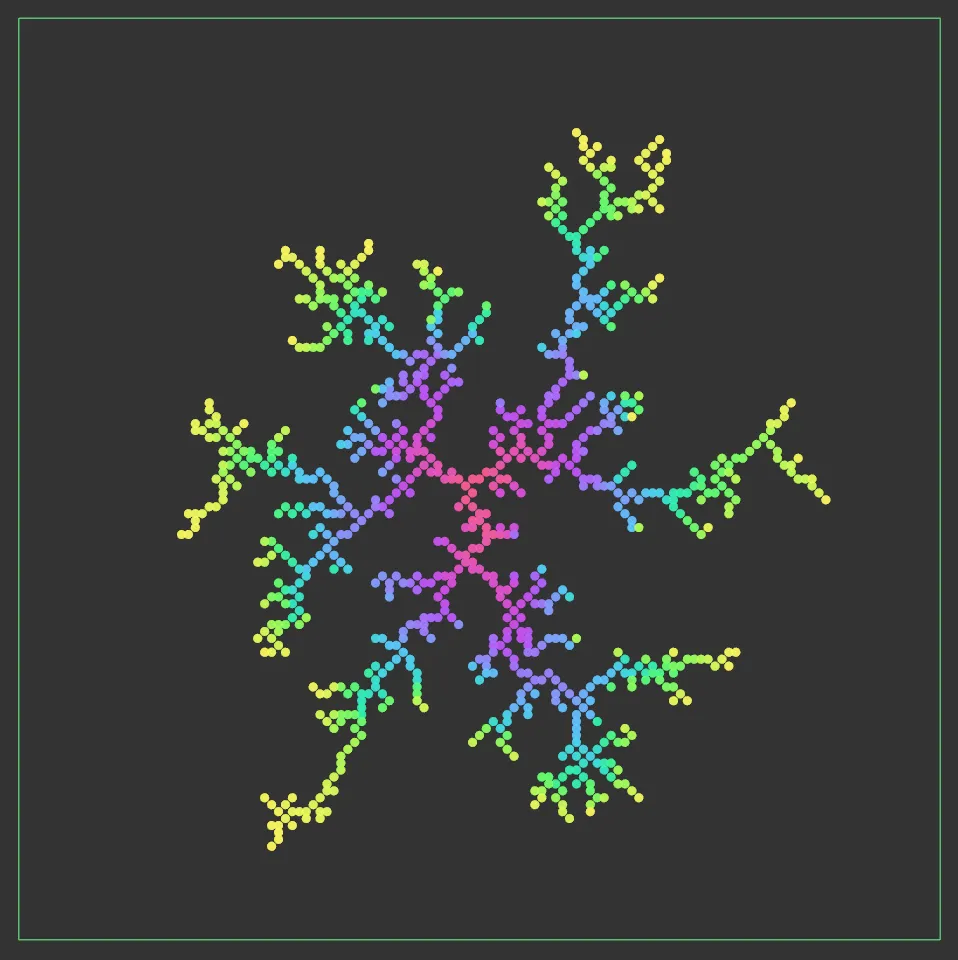
This image shows the Seed Generation set to Center.
Top Center
Section titled “Top Center”Seed particles are placed at the top of the grid in the center.
If more than one seed is generated, they will be evenly spaced along the top center line of the grid.
Bottom Center, Left Center, Right Center
Section titled “Bottom Center, Left Center, Right Center”These are the same as Top Center, but the seeds are placed at the center of the respective side.
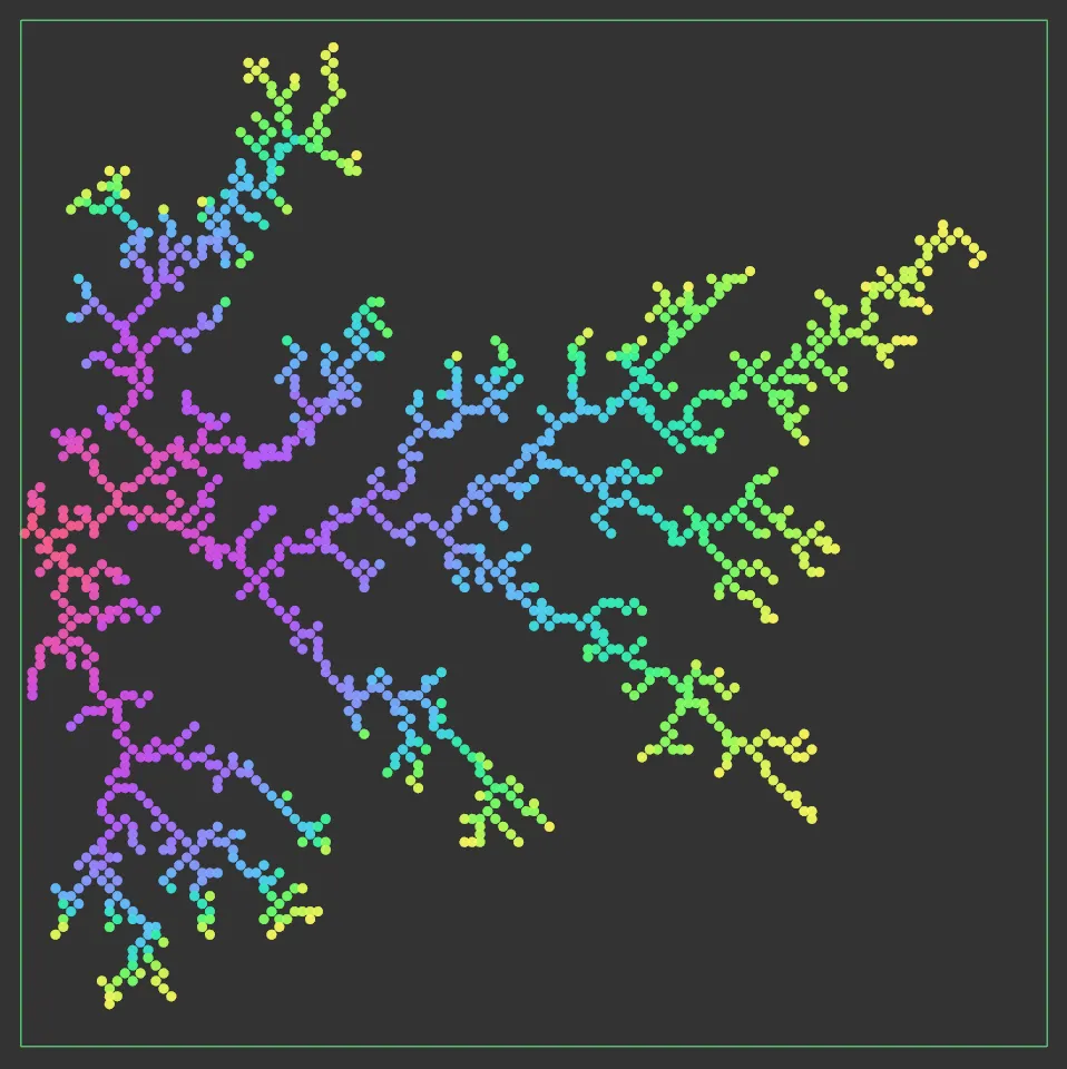
Seed Generation is set to Left Center, in this image.
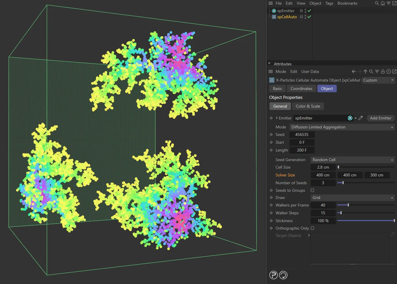
Random Cell
Section titled “Random Cell”The seed cells are generated randomly and therefore their position will change if you change the Seed parameter.
Use Target Objects
Section titled “Use Target Objects”This option enables you to specify the starting point by placing one or more objects inside the solver and dragging them into the Target Objects list.
You can use any object but the only thing that matters is its position, so a null object will work as well as any other.
The Number of Seeds parameter is not used in this mode as one seed will be generated for each object in the list.
Also, changing the object’s position after the simulation starts will have no effect.
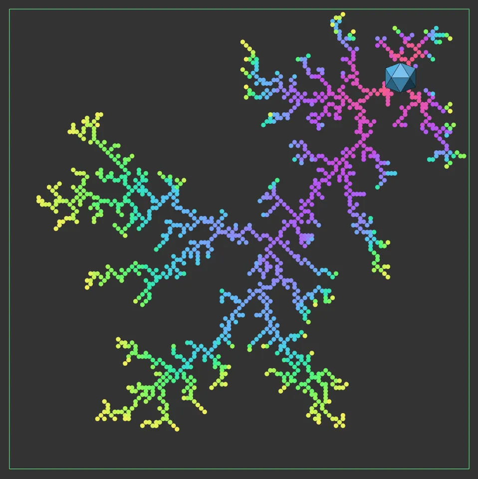
Here, the Seed Generation is set to Target Object, referencing the Platonic object in the top right-hand corner.
Determined by Emitter
Section titled “Determined by Emitter”In this mode, the emitter itself will determine where the seed particles are located.
The emitter can then be used to generate particles from any emitter shape, object, selection, etc., just as with any emitter.
If the resulting particle is outside the solver, it will be discarded and not used.
It is up to the user, therefore, to arrange the emitter or emitting object within the solver so that valid seed particles are produced.
The Number of Seeds parameter controls how many seed particles the emitter is asked to generate.
You may see fewer seeds than the requested value if some particles fall outside the solver box.
Cell Size
Section titled “Cell Size”This is the size of the cell in screen units.
If you change this, the number of cells in the solver will change and the size of the solver box may change slightly to reflect this.
But if you want to generate attractive patterns to be rendered with the XP material, you will need a high resolution with a small cell size (2-3 is recommended).
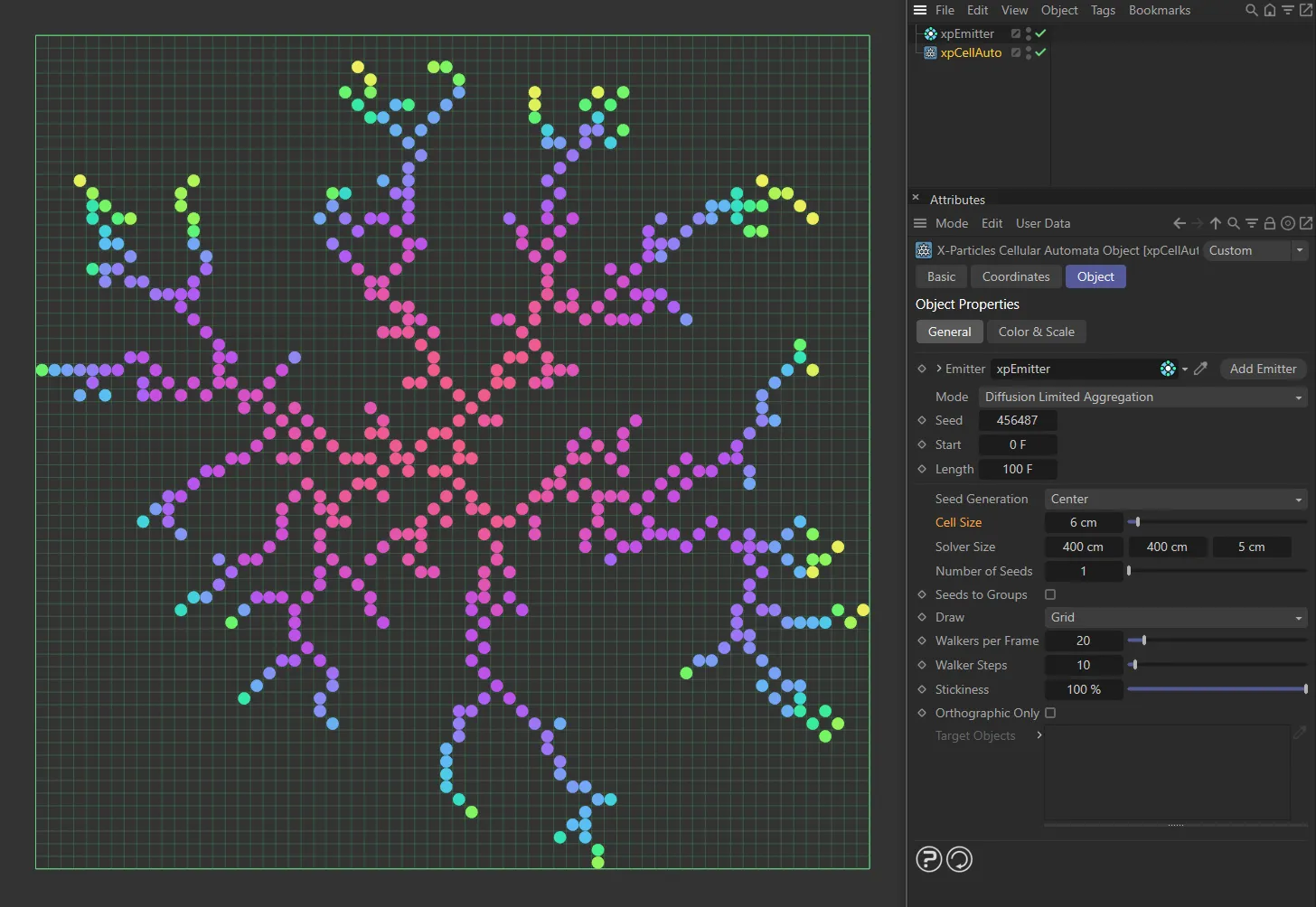
Cell Size set to 6cm.
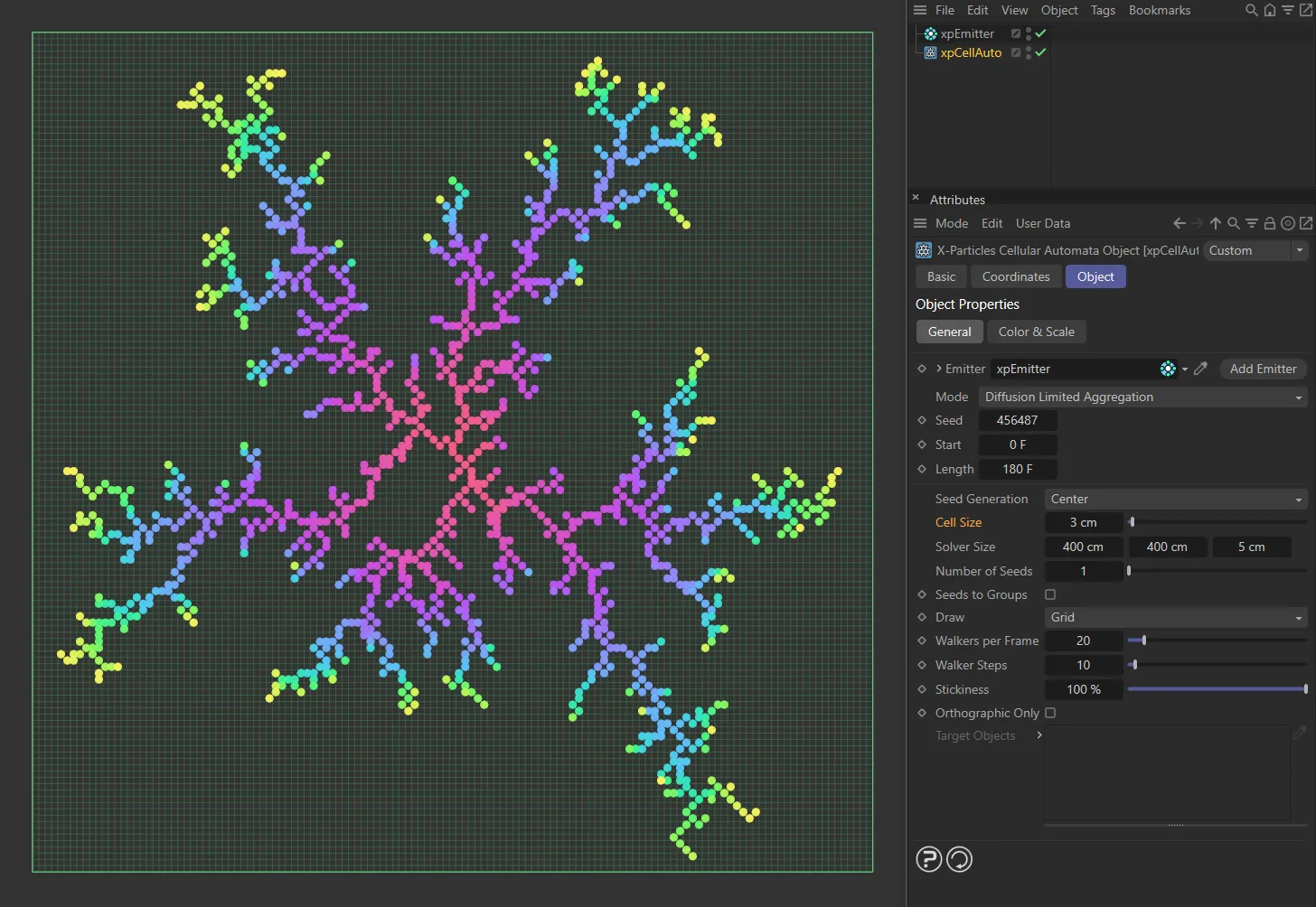
Cell Size decreased to 3cm.
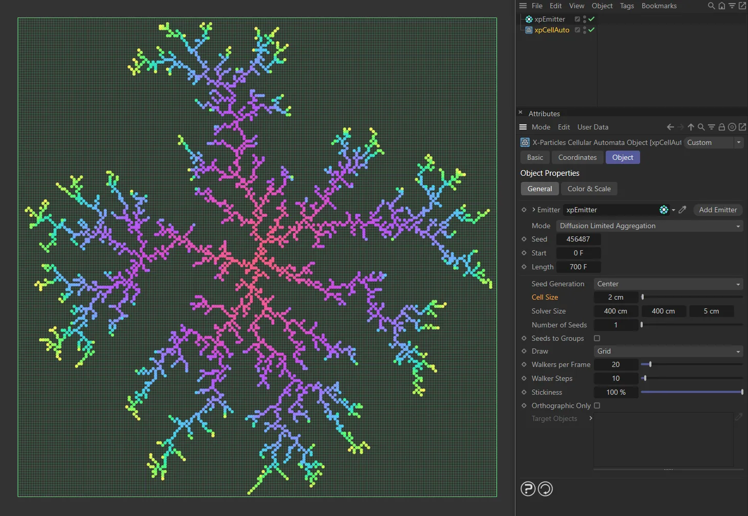
Cell Size decreased further, to 2cm.
Solver Size
Section titled “Solver Size”The size of the solver in screen units.
You can also change this with the usual resizing handles on the solver box.
If you change the solver size, the number of cells in the solver will also change.
By default, the solver is set to 400 x 400 x 10 units, which, with a default cell size of 10 units, gives 40 x 40 x 1 cells in the grid.
In general, the best results are obtained with this kind of two-dimensional grid but you can increase the Z axis value to give three-dimensional clusters, if desired.
In this image, the Solver Size is set to 400 x 400 x 5 (X, Y, Z), giving this petri-dish style.
Here, the Solver Size is 400 x 400 x 300, allowing the clusters to grow along the Z axis, giving a coral-like style.
Number of Seeds
Section titled “Number of Seeds”The number of seeds to be generated.
Not available in Use Target Objects mode, when the number of seeds is determined by the number of objects in the Target Objects list.
Seeds to Groups
Section titled “Seeds to Groups”If the emitter has one or more groups in its Groups list, it will place the generated particles into groups according to the rules in the emitter.
This will mean that the groups are spread randomly over the different particle clusters in the solver.
If this setting is enabled, all the particles in a cluster will be placed in the same group and different clusters will use different groups.
There are some rules to follow to ensure that this works:
- You must have one group per cluster (the emitter can have more than that number of groups in its list but only the ones which are required will be used).
- The groups must be in the emitter’s Groups list. Groups not present in that list will not be used.
- The cluster from the first seed will be placed in the first group, the second seed’s cluster in the second group, and so on.
If there aren’t enough groups for all the clusters, those clusters without a group will be added to the last group in the list, but the seed particle will be placed in the first group.
This may give different colors for the seed particle and other particles in the cluster, which serves as a warning that you don’t have enough groups for all the clusters being generated.
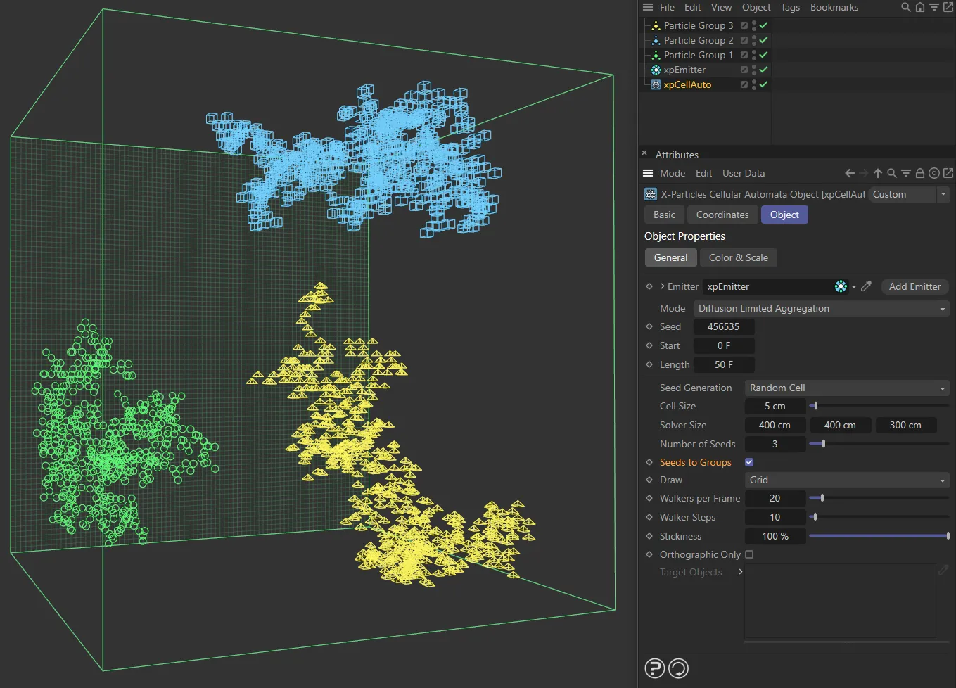
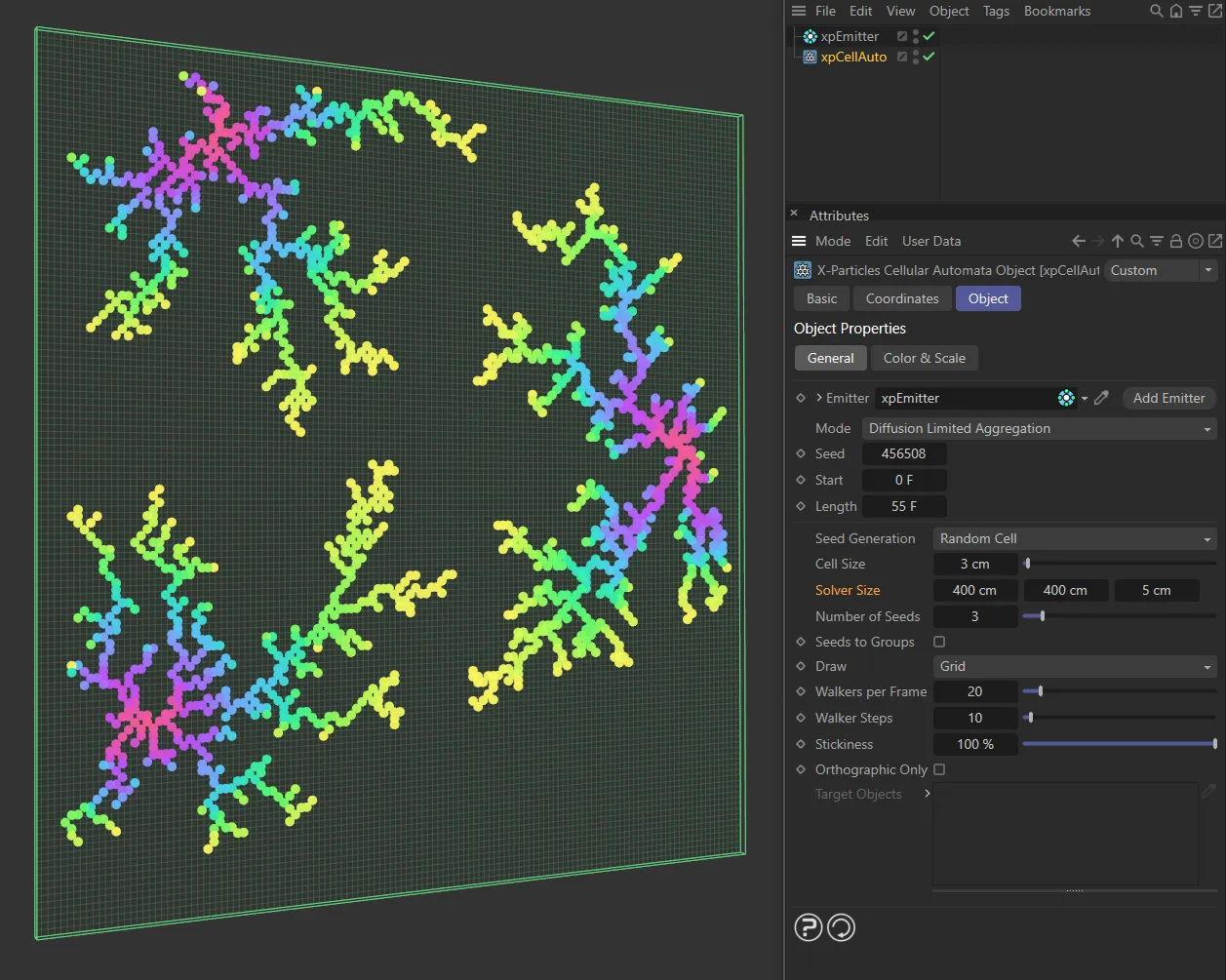
In this scene, the xpEmitter has three particle groups, each with its own particle Editor Display setting. Seeds to Groups is enabled in xpCellAuto, with Number of Seeds set to 3. The resulting clusters, generated at each of the three seeds, use their own individual particle group.
Set as Grid, by default, a box showing the solver size will be shown on screen, plus a grid on the ‘back’ wall of the solver to show the cell size.
This drop-down menu enables you to turn off the grid and only show the box (Box), or (Nothing) to draw nothing at all.
Walkers per Frame
Section titled “Walkers per Frame”A ‘walker’ is an invisible particle, which randomly walks around the grid until it hits the growing cluster.
At that point, it sticks to the cluster (subject to the Stickiness setting) and becomes fixed and visible.
A value of 1 in this setting would generate one walker per frame, which would take a long time to grow a reasonably-sized cluster.
By increasing this value, you can generate multiple walkers each frame but then each frame will take longer to execute and the animation of the cluster growth may appear to pop in.
A lower value gives smoother growth but requires more frames for the same result.
The default value of 20 is actually quite a conservative one and you should be able to increase this to 50-100 without any issues.
In this animation, Walkers per Frame is set at 20.
Walkers per Frame is increased to 80, in this animation.
Walker Steps
Section titled “Walker Steps”Once a new walker has been generated, it will be ‘walked’ in random fashion around the solver until it hits a cell which has been filled by a particle already.
When it does, it will stick to that cell (subject to the Stickiness setting) and a new particle is generated.
This parameter controls how many steps the walker will take before finding a filled cell to stick to.
If it hasn’t found a cell after this many tries, it gives up and a new walker is generated, up to the limit in Walkers per Frame.
The higher the number of steps, the greater the chance that the walker will find a particle to stick to, so particle counts are higher and the cluster a little more dense.
In general, you need only increase this value if you find that few particles are being generated and the cluster is slow to grow.
Stickiness
Section titled “Stickiness”By default, this is set to 100%, which means that a particle will stick to the cluster as soon as it hits an existing particle.
Most frequently, the particle which is hit will be on the extremities of the cluster, leading to long, feathery clusters.
Reducing this value will reduce the chance of the particle sticking on its first hit, so some will stick to existing particles deeper within the cluster, leading to a more dense, solid appearance.
Stickiness is set to 5% in this animation.
In this scene, the Stickiness is raised to 75%.
Orthographic Only
Section titled “Orthographic Only”If this setting is disabled (the default state), newly generated ‘walker’ particles may be located at any of the cells surrounding an existing particle.
This means that the network can grow diagonally as well as along the X, Y, and Z axes.
If enabled, the network cannot grow diagonally, only along the three axes.
This is of most use when there are multiple seeds.
If this box is unticked, the particle clusters can intermingle, with branches of one cluster crossing over branches of another one.
If ticked, this cannot happen.
You will see that, when enabled, the clusters are more solid and tend to produce a mass of particles; when disabled, the tendency is to produce long branching chains of particles.
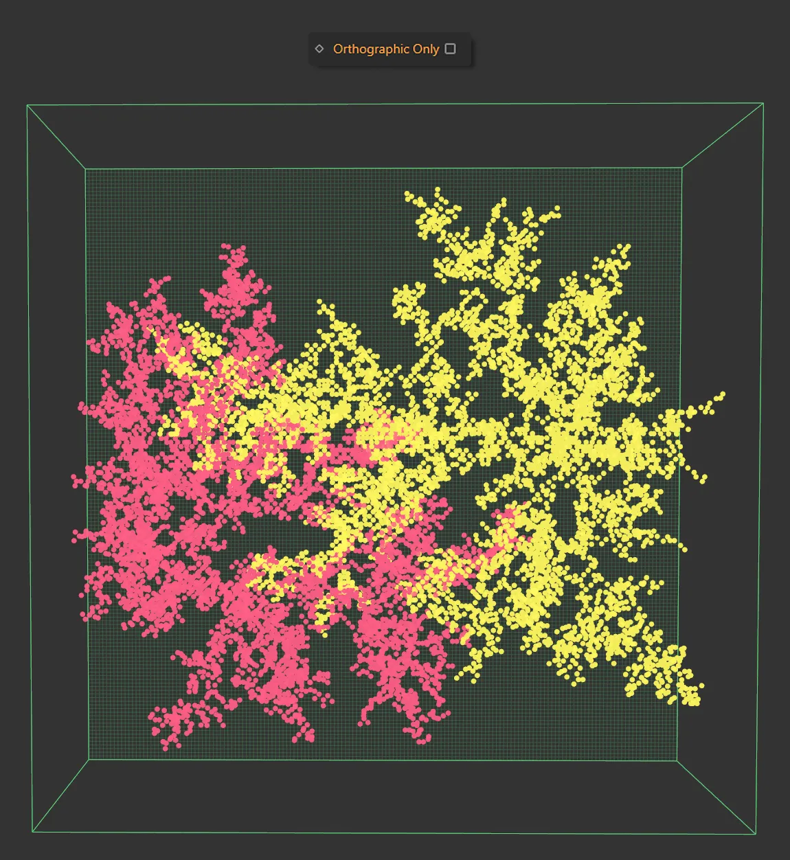
Orthographic Only is disabled here, allowing intersecting branches.
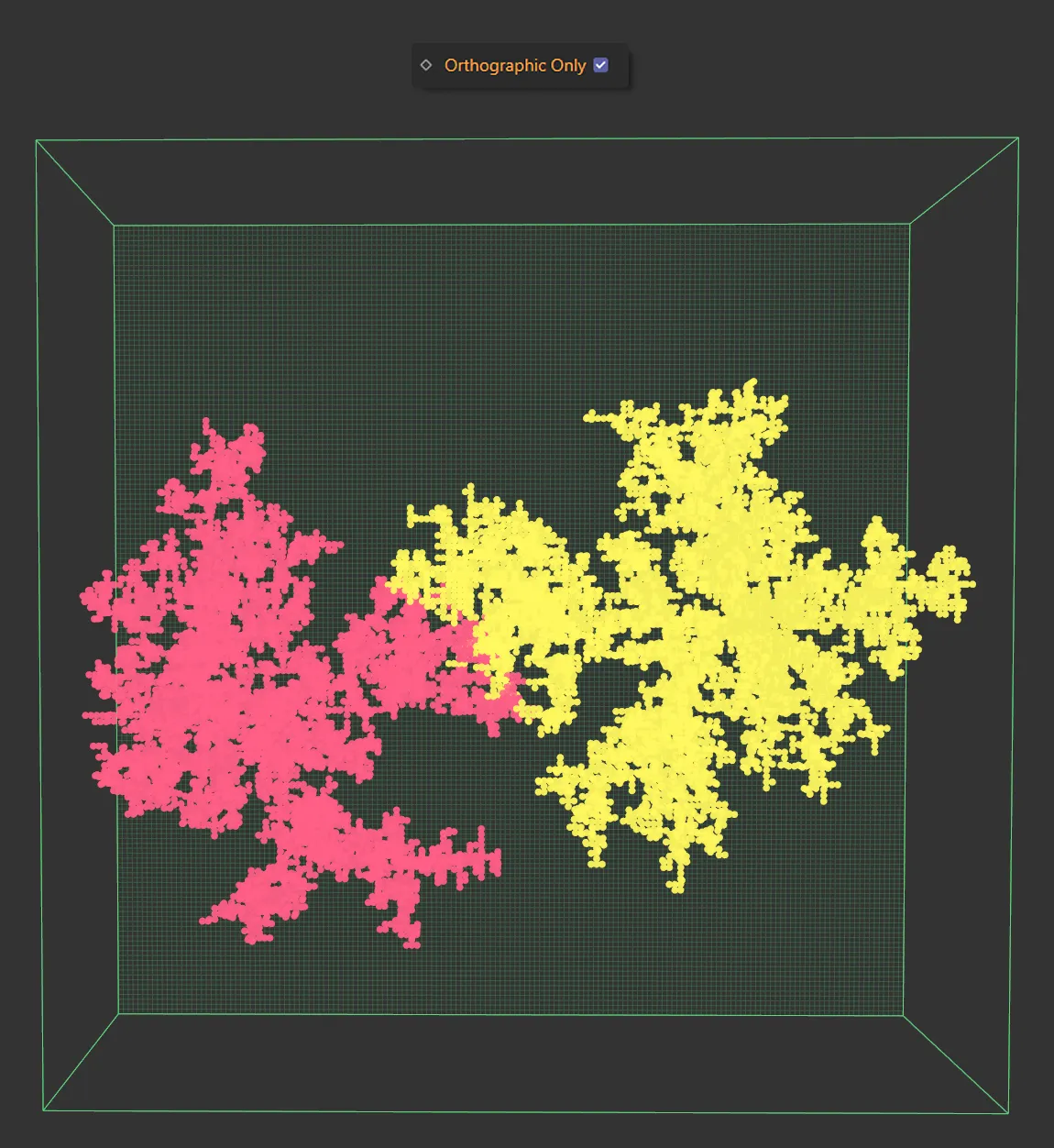
Orthographic Only enabled. Branches still intertwine but do not cross over.
Target Objects
Section titled “Target Objects”A list for the target objects when using Use Target Objects mode.
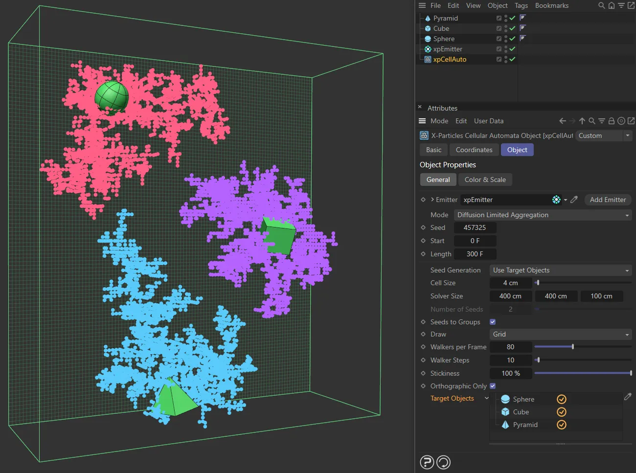
In this scene, there are three target objects: a Sphere, a Cube and a Pyramid, all dropped into the Target Objects list. They are each acting as seeds for the cell pattern.
Elementary and Game of Life mode settings
Section titled “Elementary and Game of Life mode settings”In Elementary and Game of Life modes, the interface changes slightly (the Rule No. and Start in Random State settings are not available in Game of Life mode):
Rule No.
The rule used for the Elementary mode.
These are the classic 256 different rules for elementary cellular automata.
It is not available in Game of Life mode.
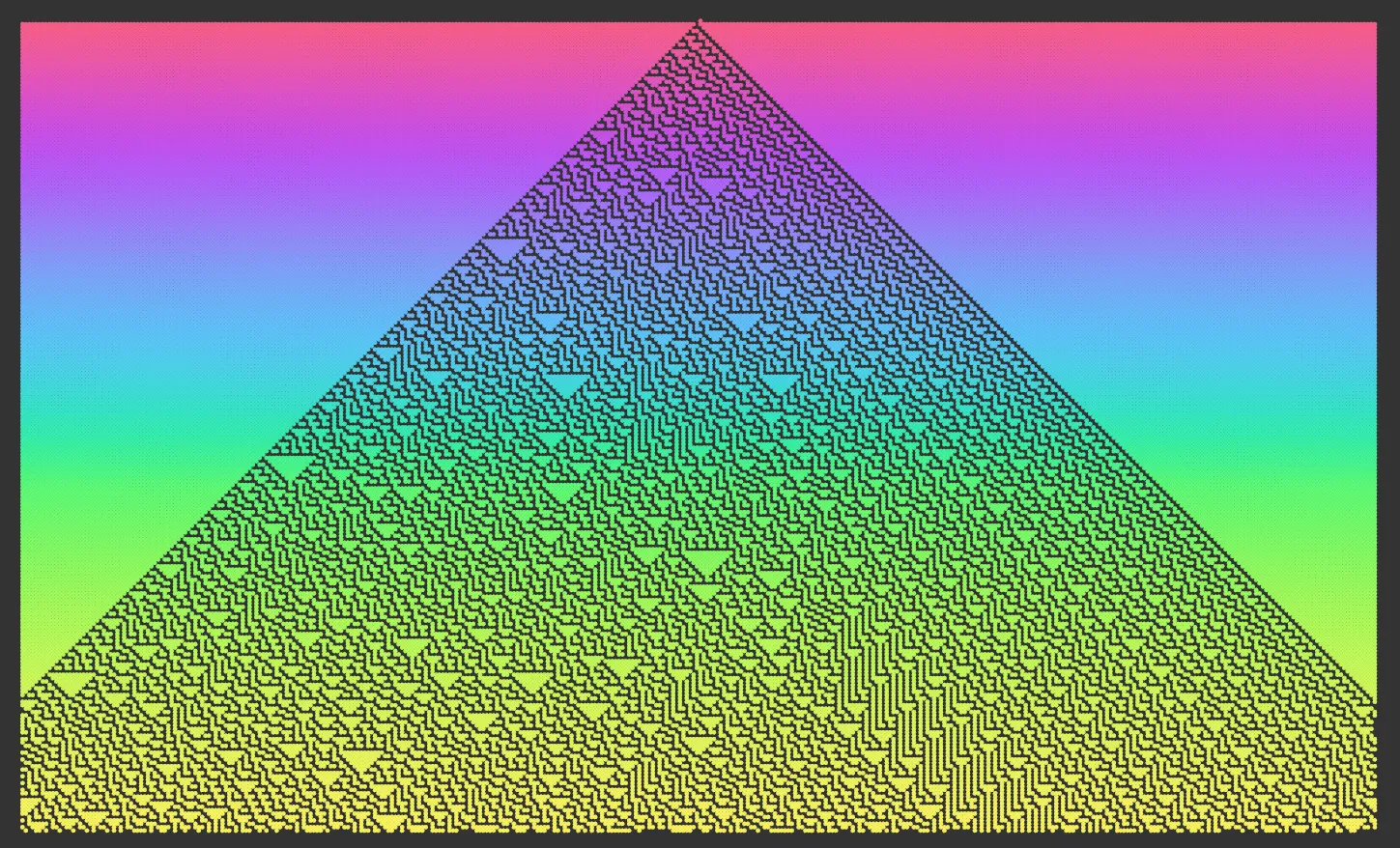
Rule No. 30.
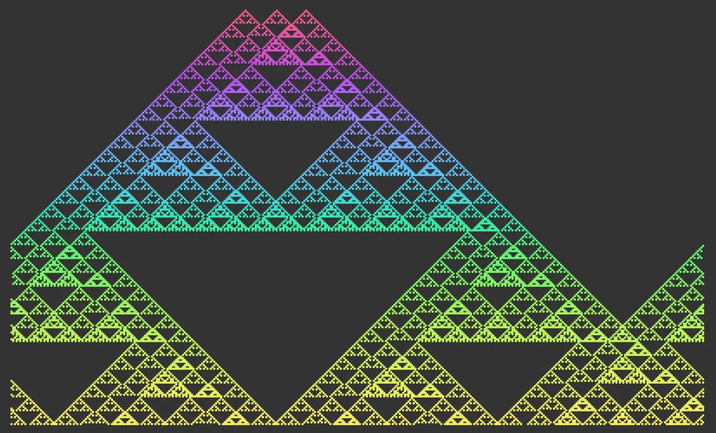
Rule No. 45.
Rule No. 57.

Rule No. 79.
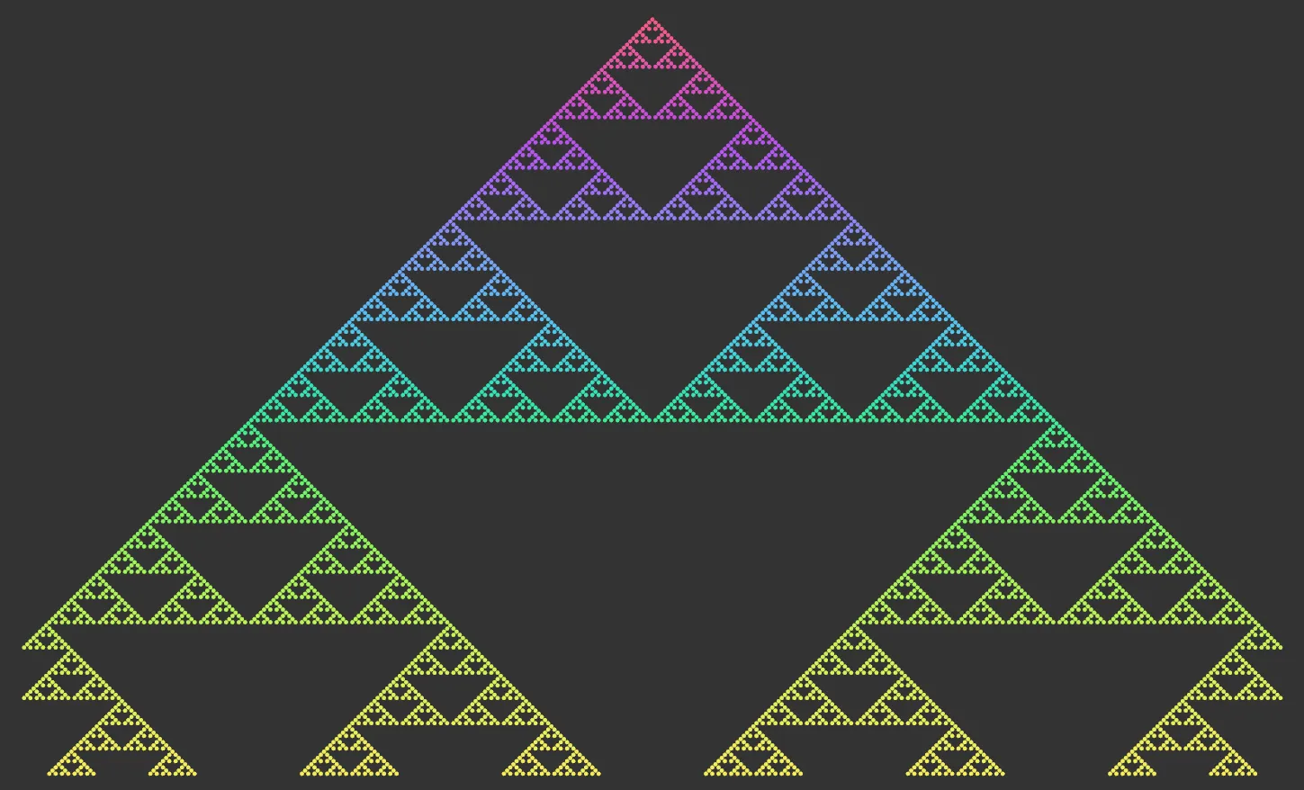
Rule No. 90.
Rule No. 149.
Start in Random State
Section titled “Start in Random State”Only available in Elementary mode.
By default this is disabled, and the starting point (the ‘seed’) for the simulation will be one single particle in the center of the top row of the grid.
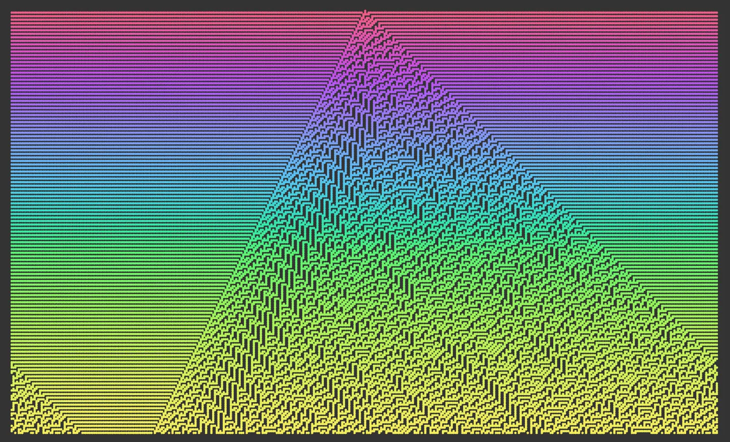
If this setting is enabled, particles are randomly generated along the top row to produce multiple seed points.
The number of seed particles is controlled by the Threshold setting.
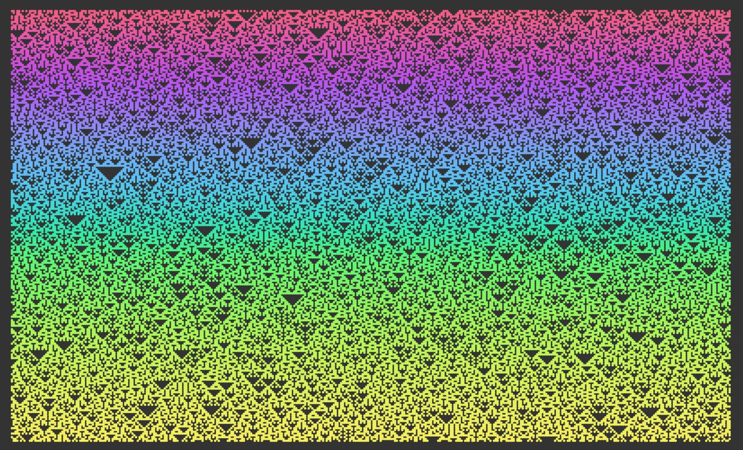
Start in Random State enabled, with a Threshold value of 50%. Note: This is with the default Rule No. 90 set, which can be compared with the image above, to see the difference.
Threshold
Section titled “Threshold”This setting controls how many seed particles are produced at the start of the simulation.
For Elementary mode, these are generated on the top row of the grid, so that if the grid has a width of 100 cells and the Threshold value is 50%, about 50 of the 100 cells will contain a particle at the start.
For Game of Life mode, the particles are randomly distributed across the 2D grid and this value controls how much of the grid is initially filled with particles when the simulation starts.
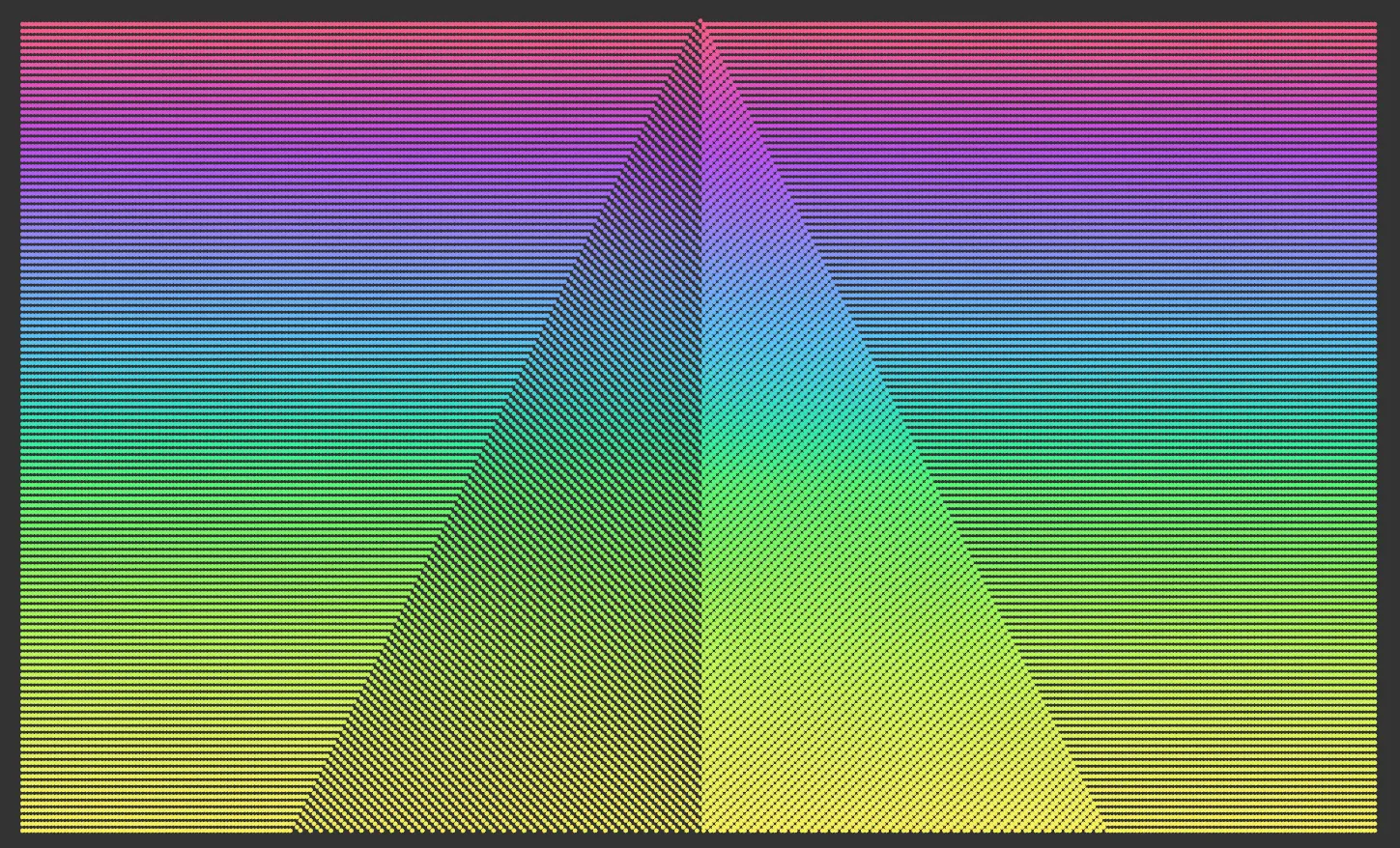
The same settings as the above, with a Threshold value of 1%.
Here, the Threshold is raised to 99%.
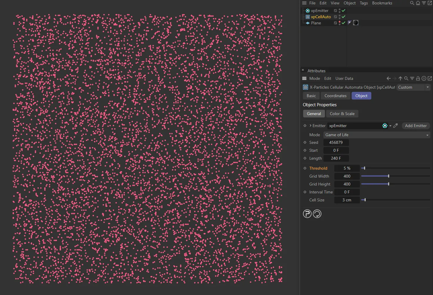
Here, xpCellAuto is set to the Mode Game of Life, with a Threshold of 5% giving a low number of particles.
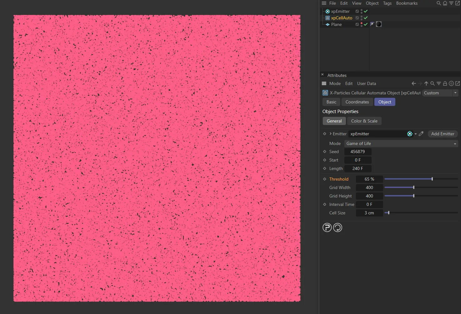
With a higher Threshold value of 65%, in this image, the amount of starting particles is greatly increased.
Grid Width, Grid Height
Section titled “Grid Width, Grid Height”The width and height of the grid in terms of the number of cells it contains.
If the cell size changes, the number of cells will not change, therefore the grid will keep the same number of cells but will change in size, though you will not see this until the animation runs.
If you alter these values, the cell size is unaffected so the number of cells will change.
Interval Time
Section titled “Interval Time”This is only used for Game of Life mode and is the interval between iterations of the simulation.
By default, it is set to zero, so another iteration will occur on each frame, which results in a very fast simulation.
If you set it to any non-zero value, that much time elapses between iterations.
This lets you see more clearly what is happening to the particles.
Cell Size
Section titled “Cell Size”The actual space in scene units between each cell.
You can increase this if you want to use larger particles to avoid them overlapping, or decrease it for small particles and a higher-resolution result.
Altering this parameter will increase or decrease the size of the grid but the number of cells will remain the same.
You can also alter the size of the grid by changing the Grid Width and Grid Height values.
Color & Scale tab
Section titled “Color & Scale tab”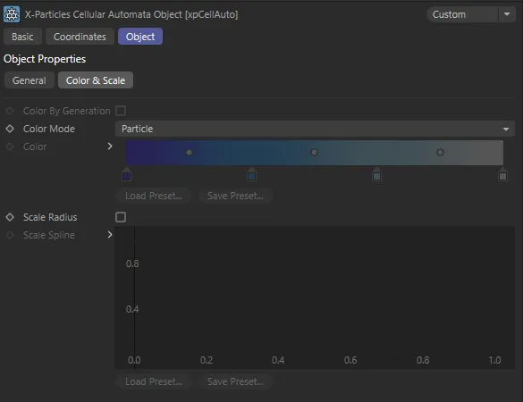
xpCellAuto Color & Scale tab settings.
Color by Generation
Section titled “Color by Generation”This parameter is only enabled in Elementary or Game of Life modes.
If this is enabled, the particles will be colored according to the time at which they are generated.
Particles generated at the start of the animation (the Start time) will receive the color at the left of the Color gradient; particles generated at or after the Length time has elapsed will receive the color at the right of the gradient.
If that happens you should adjust the Length setting accordingly.
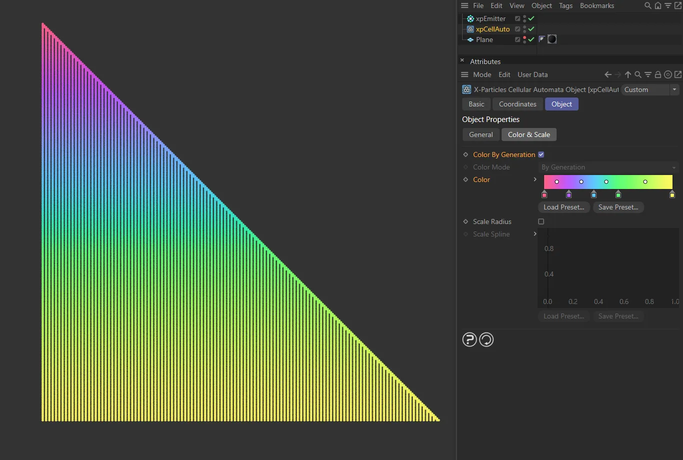
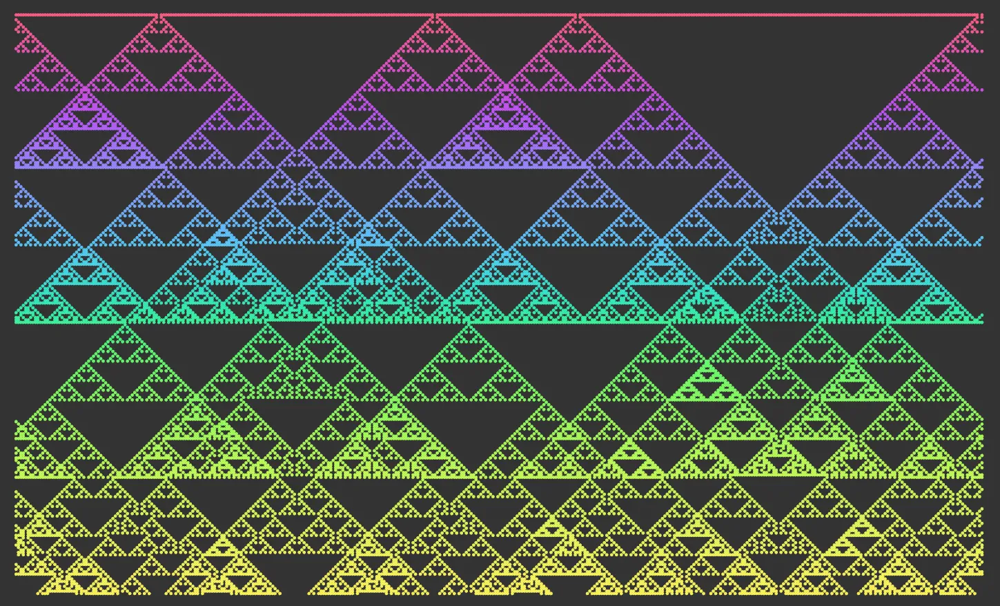
In this image, the Mode is Elementary, with Color By Generation enabled.
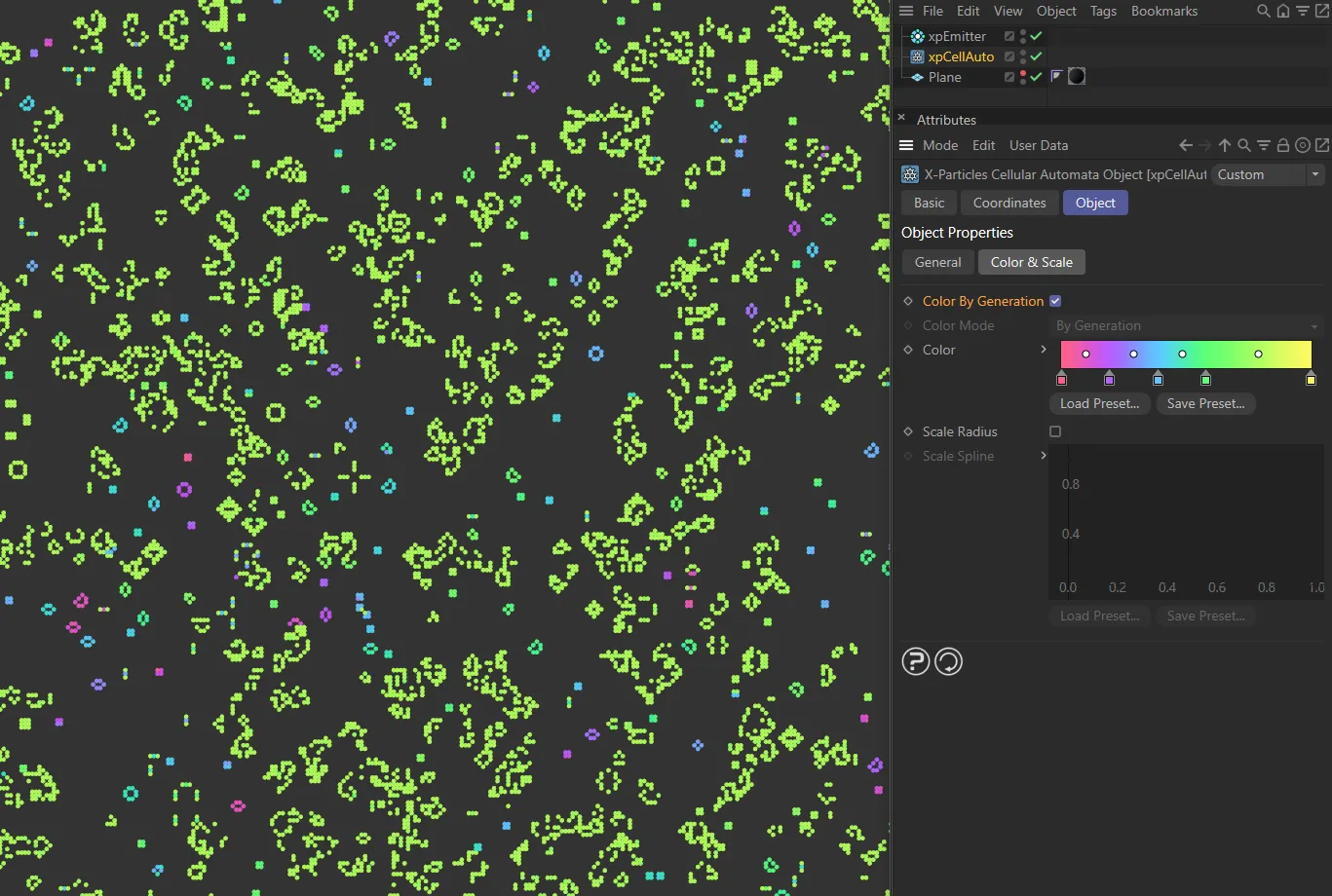
This second image also has Color By Generation enabled, but in the Mode of Game of Life.
Color Mode
Section titled “Color Mode”Set as Particle, by default, this drop-down is only used in Diffusion Limited Aggregation mode.
It controls how the particles are colored.
The other options are: Random, By Generation and By Cluster.
Particle
Section titled “Particle”The particle color is used without changes.
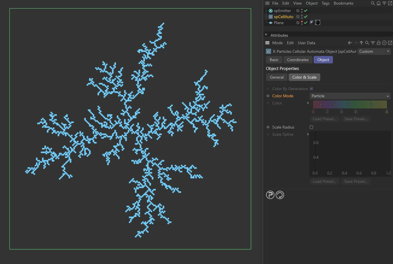
Color Mode set to Particle, with the xpEmitter Particle Color in the default, blue.
Random
Section titled “Random”A random color from the Color gradient is used.
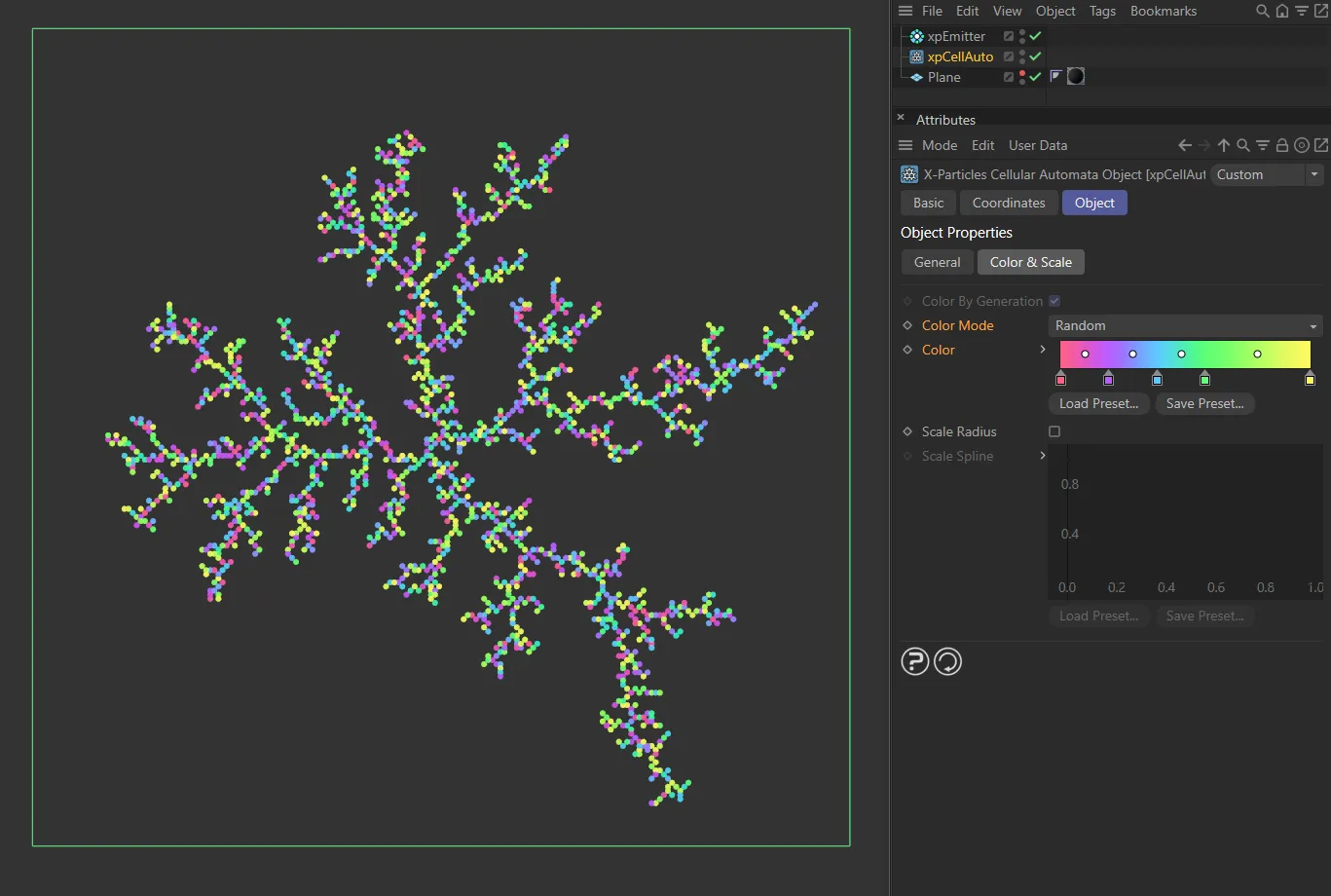
Here, the Color Mode is Random, with each particle getting a random color from the user gradient.
By Generation
Section titled “By Generation”This mode works in exactly the same way as the Color by Generation setting in Elementary or Game of Life modes.
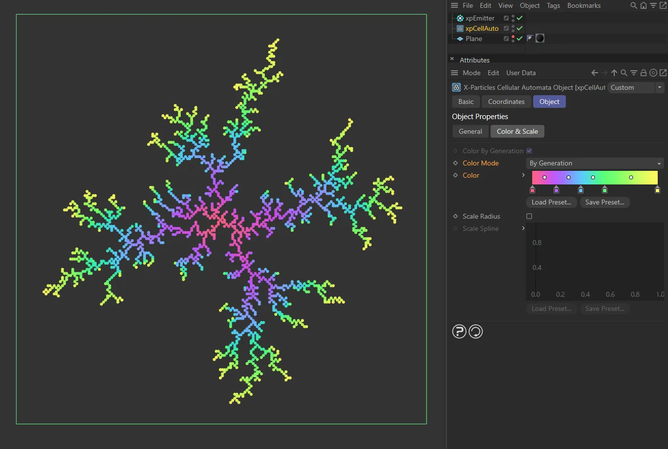
In this image, the Color Mode is set as By Generation.
By Cluster
Section titled “By Cluster”Each cluster is given a color from the Color gradient. If there is only one cluster, the color at the right-hand end of the gradient used.
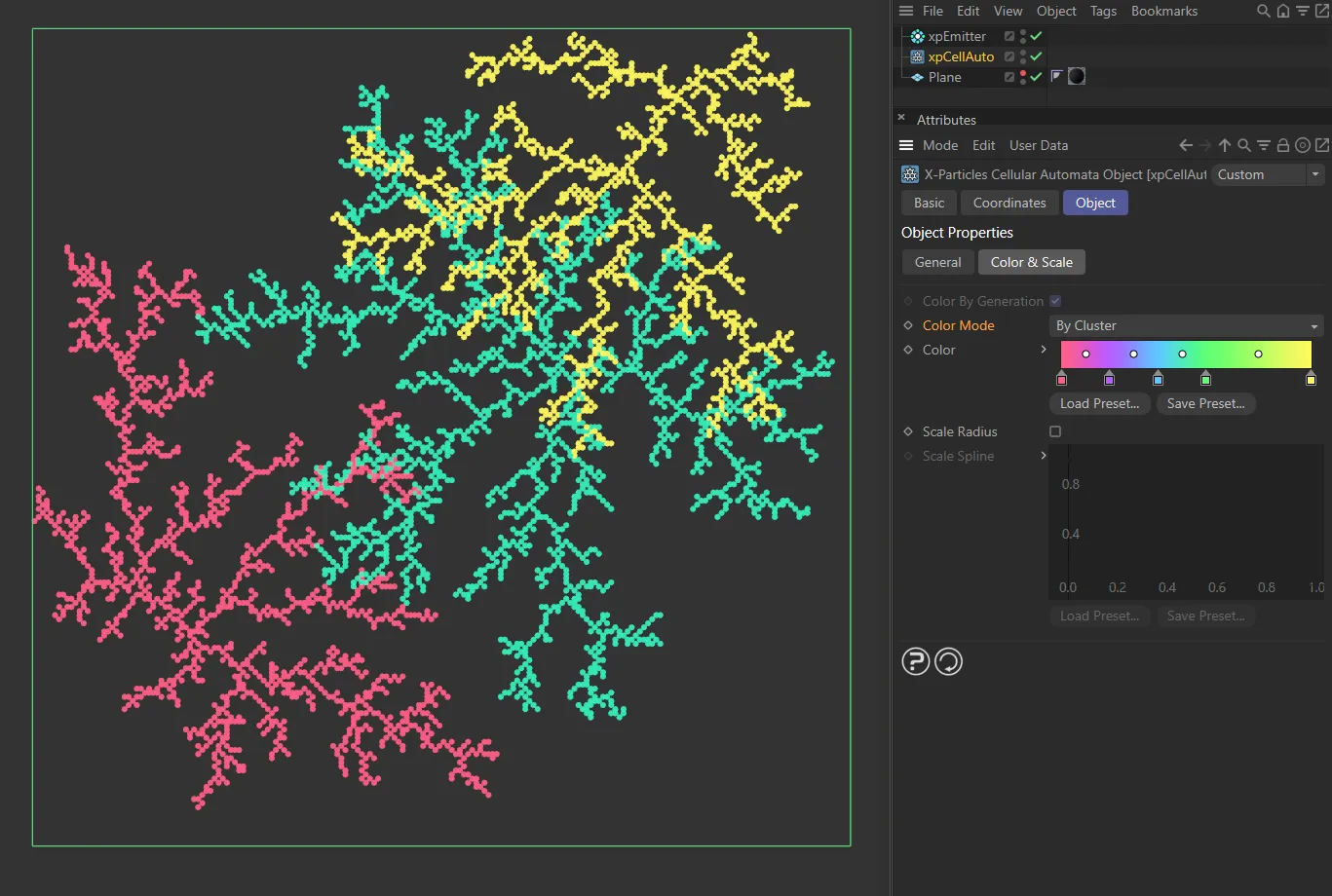
This final image shows the Color Mode of By Cluster.
The color gradient to use if Color by Generation is enabled or By Generation mode is selected in Color Mode.
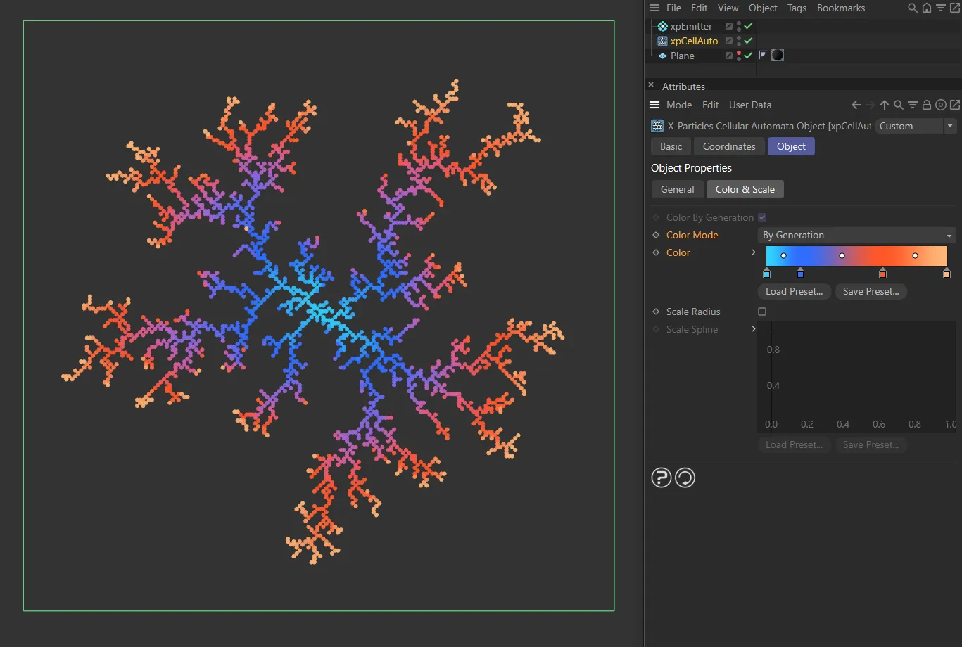
With the Color Mode set as By Generation, here the Color is taken from a user color gradient.
Scale Radius
Section titled “Scale Radius”As with particle color, you can change the radius of the generated particles according to their time of generation.
In this case a spline control is used to scale the radius up or down.
Scale Spline
Section titled “Scale Spline”The spline control to use if Scale Radius is enabled.
Scale Radius enabled, with the default Scale Spline setting.
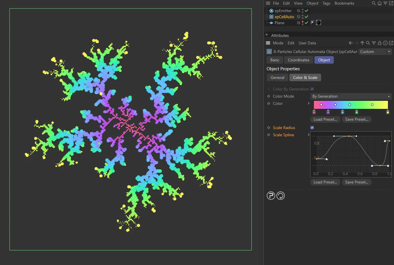
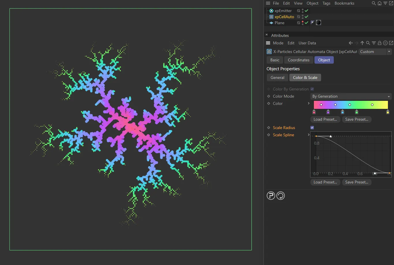
This final image also has Scale Radius enabled, but with a custom Scale Spline setting.
Copyright © 2026 INSYDIUM LTD. All rights reserved.