xpBulletConstraints
xpBulletConstraints links dynamic xpBullet objects together using different constraint types, such as hinges, springs and sliders.
Object Properties
Section titled “Object Properties”
xpBulletConstraints menu settings.
Objects
Section titled “Objects”Drag the dynamic objects, that you want to constrain, into this list.
Doing so will open up parameter settings, below, which can be set separately for each individual object in the list.
In this animation, a Cylinder and a Cube (as the child) are dropped into the Objects field and the Constraint Type of Slider is selected. An Angular Min of -140 degrees and an Angular Max of 140 degrees are set, setting up a pendulum, with the Cube swinging from the Cylinder between those two degree values.
Constraint
Section titled “Constraint”Constraint Type
Section titled “Constraint Type”Set as Fixed, by default, these are the different constraint type options.
The alternative modes are: 6 Degrees of Freedom, Cone, Hinge, Point to Point, Slider, Spring and Sticky.
Some modes have additional parameter settings (described below).
6 Degrees of Freedom
Section titled “6 Degrees of Freedom”This Constraint Type lets you define Linear Limits and Angular Limits to the constraint, in six degrees: the three axes (X, Y and Z) as well as the heading, pitch and bank.
Each axis can be fixed (default setting), free or customized.
Constraint Type set to 6 Degrees of Freedom, with a Custom Limit on the (bank) B Limit and angular limits set. The cube is free to rotate on the bank until it reaches the 25 degrees upper and lower limit set.
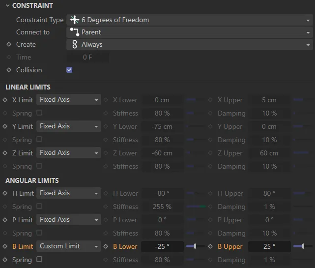
User Interface (UI) detailing the settings for the animation on the left.
This second scene has the same settings as the above except there are now linear limits set, with a Custom Limit on the (X-axis) X limit, of between -40 and 40cm.
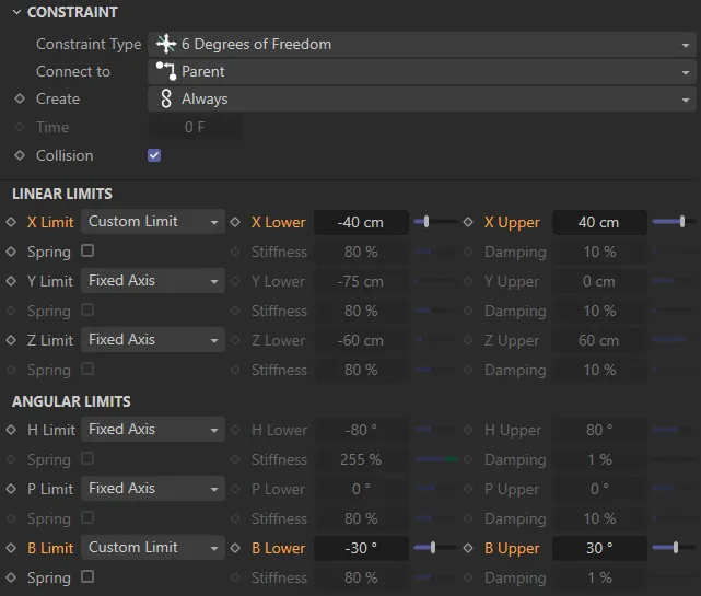
UI detailing the settings for the animation on the left.
Like the Point to Point type, below, this constraint works around a pivot point, but this constraint, allows swing and twist options, between defined points.
This setting is particularly effective with creation of the dynamic between limbs.
The Constraint Type is now set to Cone, with the settings on the right directing the swing and twist movements.
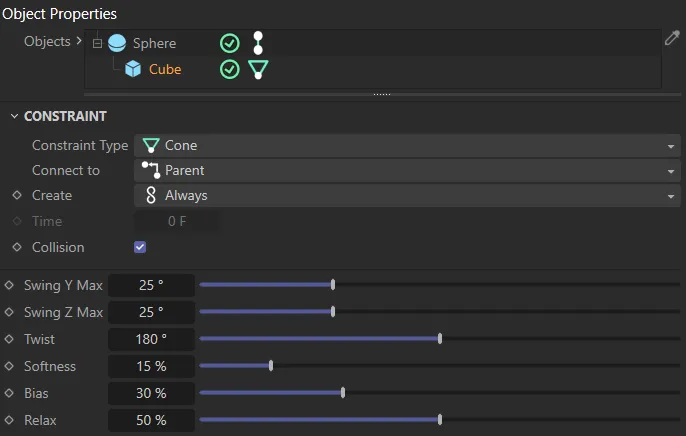
UI detailing the settings for the animation on the left.
The constraint will remain at a fixed distance between the objects in the Objects list.
In this animation, the Constraint Type is set to Fixed, with the Cube fixed on the end of the Cylinder.
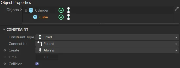
UI detailing the settings for the animation on the left.
This setting restricts the translation and two additional angles so that the objects can only rotate around one axis (the Z axis of the constraint), creating a hinge-like constraint between the objects in the Objects list.
Animation to demonstrate the Constraint Type of Hinge, with a High value of 90 degrees setting the maximum angle of the hinge.
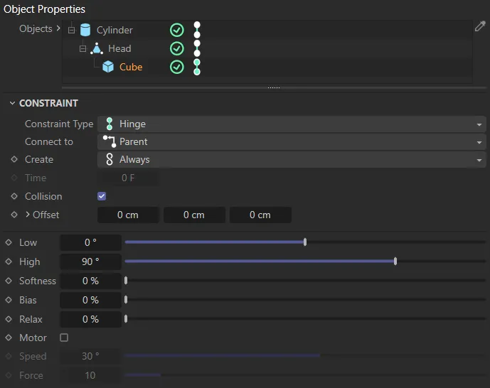
UI detailing the settings for the animation on the left.
Point to Point
Section titled “Point to Point”This setting constrain the objects in the Objects list based on their central points, pivoting at this point.
This is a useful setting in the creation of chain link effects.
In this scene the Constraint Type is Point to Point, pivoting from the central points of the two objects.
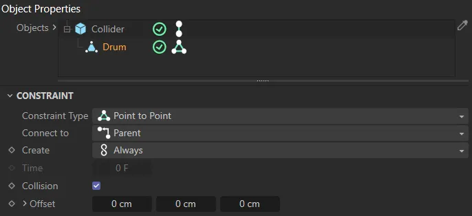
UI detailing the settings for the animation on the left.
This animation also has the Constraint Type set as Point to Point, but the object is now an xpShatter generator, with the central points of each shattered piece connected between the Min Distance and Max Distance limits.
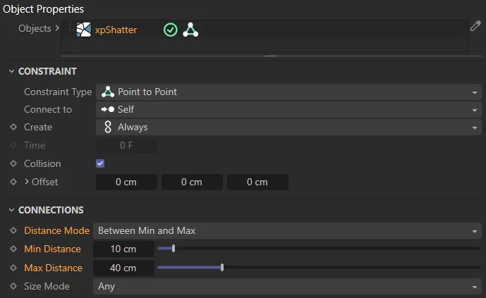
UI detailing the settings for the animation on the left.
Slider
Section titled “Slider”Creates a constraint with a sliding axis (on the Z axis) between the objects in the Objects list, which can also be rotated around.
The Constraint Type is set to Slider here, with a Linear Max value of 25cm restricting the sliding.
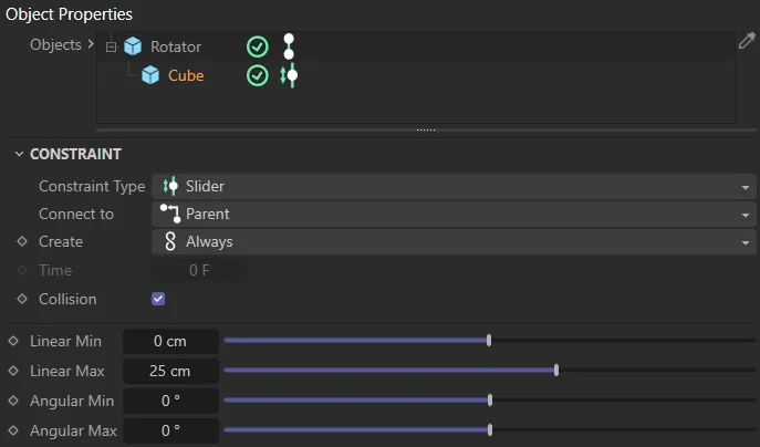
UI detailing the settings for the animation on the left.
Spring
Section titled “Spring”This constraint has three degrees of freedom, around the X, Y and Z axes and acts like the suspension on a wheel of a vehicle.
Constraint Type set to Spring, with the UI on the right detailing the settings, with a Type of Linear set.
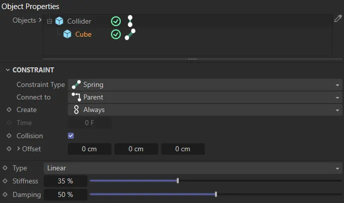
UI detailing the settings for the animation on the left.
By comparison to the scene above, this time the Type is set to Linear + Angular, allowing a degree of rotation.
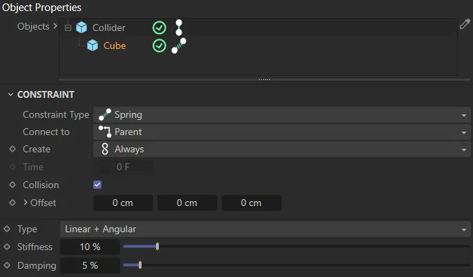
UI detailing the settings for the animation on the left.
Sticky
Section titled “Sticky”This constraint sticks objects to each other.
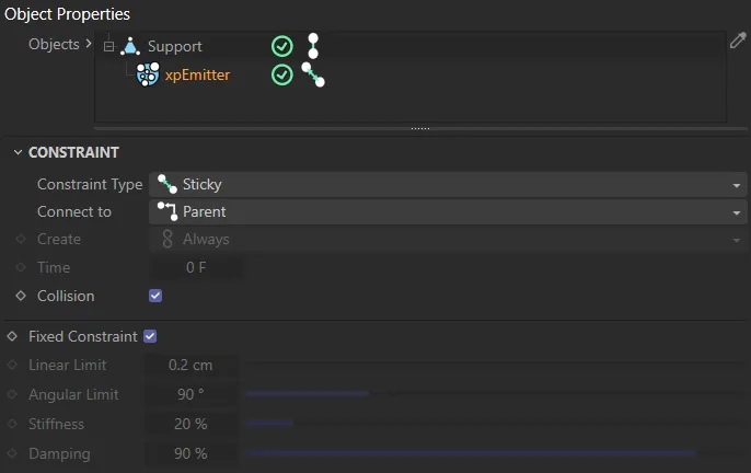
UI detailing the settings for the animation on the left.
With the Constraint Type set to Sticky, the particles stick to the Support object, when they land on it.
Connect to
Section titled “Connect to”Set as Parent, by default, this sets the relationship of the object that is highlighted, in the Objects list, to any other objects present/it is connected to.
The other options are: Children and Self.
Parent
Section titled “Parent”The object that the highlighted object is connected to is the parent, in the relationship.
Therefore the highlighted object is the child.
Children
Section titled “Children”With this setting, the highlighted object is assuming a parental role and any other connected objects are children of it.
The highlighted object is only setting a constraint upon itself.
An example of this setting can be seen in the animation above, with the Constraint Type set to Point to Point and the xpShatter generator having constraints on the parts of itself.
Create
Section titled “Create”Set as Always, by default, this defines when the constraint is taking place.
The alternative settings are: Start, Time and Collision.
Always
Section titled “Always”Viable connections are searched for throughout the scene.
Viable connections are only searched for at the start of the animation.
Allows you to start any constraints at a time in the scene, defined by the Time parameter.
Collision
Section titled “Collision”Constraints will begin on collision, as long as the Collision setting is enabled.
The time value to use (in frames), when Create is set to Time.
Collision
Section titled “Collision”When enabled, constraints will be activated by a collision between objects in the Objects list.
Offset
Section titled “Offset”Only available in the Constraint Types of Hinge, Point to Point and Spring.
Offset your constraints from the object in the Object field.
Clicking on the small arrow, will reveal the Object parameter, which allows you to select the object to offset from and then drag and drop it into this field.
Connections
Section titled “Connections”Distance Mode
Section titled “Distance Mode”Set as Any, by default, this uses the distance between dynamic objects to determine if constraints are made.
The other options are: Less Than Max, Greater Than Min and Between Min and Max.
Sets constraints between objects at any distance.
Less Than Max
Section titled “Less Than Max”Only sets constraints between objects closer than the Max Distance value.
Greater Than Min
Section titled “Greater Than Min”Only sets constraints between objects further away than the Min Distance value.
Between Min and Max
Section titled “Between Min and Max”Only sets constraints between objects within the Min Distance and Max Distance values.
Max Distance
Section titled “Max Distance”The value to use when Distance Mode is set to Less Than Max or Between Min and Max.
Min Distance
Section titled “Min Distance”The value to use when Distance Mode is set to Greater Than Min or Between Min and Max.
Size Mode
Section titled “Size Mode”Set as Any, by default, the size an object has to be in order for the connections to be made.
For example, if set to Greater Than Min, with a value of 50cm and the Cube child object is at 45cm, a connection will not be made.
The alternative settings are: Less Than Max, Greater Than Min and Between Min and Max.
Sets constraints between all points.
Less Than Max
Section titled “Less Than Max”Only sets constraints between objects smaller than the Max Size value.
Greater Than Min
Section titled “Greater Than Min”Only sets constraints between objects larger than the Min Size value.
Between Min and Max
Section titled “Between Min and Max”Only sets constraints between objects within the Min Size and Max Size values.
Max Size
Section titled “Max Size”The value to use when Size Mode is set to Less Than Max or Between Min and Max.
Min Size
Section titled “Min Size”The value to use when Size Mode is set to Greater Than Min or Between Min and Max.
Breaking
Section titled “Breaking”Break on Impulse
Section titled “Break on Impulse”Enable to break constraints on impulse.
Break Threshold
Section titled “Break Threshold”Sets the threshold of the impulse at which breaking takes place, controlling the impact of the breaking.
There are two modes available: Relative and Absolute.
Relative
Section titled “Relative”Relative is when the Variation amount is added or subtracted from the Break Threshold, relative to the Break Threshold value.
If the Break Threshold is 100, and Variation, in Relative mode is 5%, the varied Breaking on Impulse occurs with thresholds anywhere between 95 and 105.
Absolute
Section titled “Absolute”Absolute is when the Variation amount adds or subtracts a defined amount to the initial Break Threshold.
The amount is user-defined in the Variation parameter.
Variation
Section titled “Variation”Gives a degree of variation to the breaking, based on the Mode value set.
Break at Time
Section titled “Break at Time”Enable to set a time, in frames, when the breaking will occur.
The time value to use, when Break at Time is enabled.
6 Degrees of Freedom mode settings
Section titled “6 Degrees of Freedom mode settings”These settings are only available in the 6 Degrees of Freedom mode.
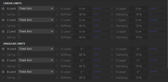
Additional settings in the Constraint Type of 6 Degrees of Freedom.
Linear Limits
Section titled “Linear Limits”X Limit, Y Limit, Z Limit
Section titled “X Limit, Y Limit, Z Limit”Set as Fixed Axis, by default, this defines how the linear translation is set.
The alternative settings are: Free Axis and Custom Limit.
Fixed Axis
Section titled “Fixed Axis”The translation is locked.
Free Axis
Section titled “Free Axis”Scene objects in the Objects list are now free to travel on the axis defined.
Custom Limit
Section titled “Custom Limit”Allows you to define per axis distance limits on translations.
X Lower, X Upper, Y Lower, Y Upper, Z Lower, Z Upper
Section titled “X Lower, X Upper, Y Lower, Y Upper, Z Lower, Z Upper”Only available when the Limit setting (X, Y and/or Z) is set to Custom Limit.
Allows you to define the minimum and maximum translations.
Spring
Section titled “Spring”Only available when the Limit setting (X, Y and/or Z) is set to Free Axis, giving a spring effect, between the limits set.
By enabling this, the Stiffness and Damping parameters become available, to give control over the free constraints.
Stiffness
Section titled “Stiffness”Sets the stiffness of the spring translation between the limits set.
Damping
Section titled “Damping”Dampens the forces applied to the translation.
Angular Limits
Section titled “Angular Limits”These settings are identical to the Linear Limits settings, except on the heading (H), pitch (P) and bank (B), instead of the X, Y and Z axes.
These parameters define how the angular translation is set.
Cone mode settings
Section titled “Cone mode settings”Swing Y Max
Section titled “Swing Y Max”Allows you to set a maximum angular degree of swing on the Y axis.
Swing Z Max
Section titled “Swing Z Max”Allows the setting of an angular degree of swing on the Z axis.
The object will twist up to the degree value set.
Softness
Section titled “Softness”Defines how easy it is for the constraint to move throughout its angle limits.
At 0 (zero) %, no angle change will occur.
Gives a control to whether objects stay towards the center or the perimeter of the cone.
At lower percentages, objects will be close to the perimeter and, at higher percentages, they will be close to the center of the cone.
Controls the degree of inertia at the beginning of animation, when any swinging begins.
The higher the setting, the smoother the transition.
Hinge mode settings
Section titled “Hinge mode settings”Sets the minimum angle of the hinge constraint.
Sets the maximum angle of the hinge constraint.
Softness
Section titled “Softness”Gives a degree of smooth movement throughout the simulation.
Gives a control to where on the hinge the object is constrained.
Controls the degree of inertia at the beginning of animation, when any swinging begins.
The higher the setting, the smoother the transition.
Enabling this will drive the constraint around the angle of the hinge at a speed set in the Speed parameter.
Once it reaches the High angle value set, it will remain there, as the motor is still working.
The speed that the motor is driving the constraint to the High degree value set.
The strength of the motor.
Slider mode settings
Section titled “Slider mode settings”Linear Min, Linear Max
Section titled “Linear Min, Linear Max”Sets the length that the objects are able to slide on the axis set.
Angular Min, Angular Max
Section titled “Angular Min, Angular Max”Sets the maximum and minimum angles that objects are permitted to rotate.
Spring mode settings
Section titled “Spring mode settings”Set as Linear, by default,
The alternative settings are: Angular and Linear + Angular.
Linear
Section titled “Linear”With this setting, there will only be linear (up and down) movements in the spring.
Angular
Section titled “Angular”This setting gives a rotational movement in the spring.
Linear + Angular
Section titled “Linear + Angular”Allows up and down and rotational movement in the spring.
Stiffness
Section titled “Stiffness”Sets the stiffness of the spring.
Damping
Section titled “Damping”Dampens the forces of the spring.
Sticky mode settings
Section titled “Sticky mode settings”Fixed Constraint
Section titled “Fixed Constraint”Enabled, by default, this adds a control over the immediate strength of stickiness.
Disabling this parameter will give a degree of freedom at the point of impact.
Linear Limit
Section titled “Linear Limit”The value set here will decide whether an object will stick or not to the object it is hitting, dependent on distance.
Angular Limit
Section titled “Angular Limit”The value set here will decide if an object will stick or not to the object it is hitting, dependant on the angle of collision.
Stiffness
Section titled “Stiffness”Sets the stiffness of the stickiness.
Damping
Section titled “Damping”Dampens the forces of the stickiness.
Display
Section titled “Display”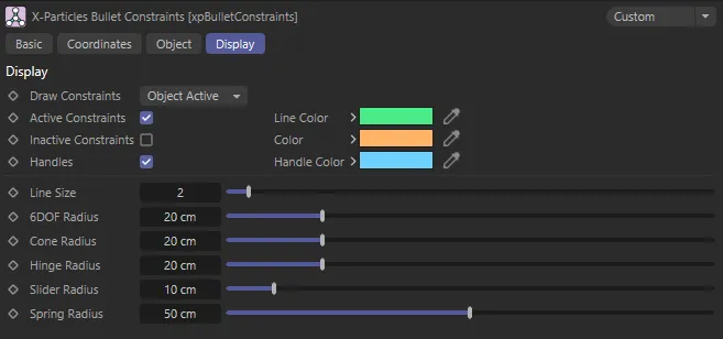
xpBulletConstraints Display tab menu settings.
These settings help you customize how the constraints are being visualized in your viewport.
Draw Constraints
Section titled “Draw Constraints”Set as Object Active, by default, this sets whether and when the constraints are visible.
The other options are: Disabled and Always.
Disabled
Section titled “Disabled”Constraints will not be visible in this mode.
Object Active
Section titled “Object Active”Object Active displays any active constraint connections generated by the xpBullet constraints.
Constraints are then visible when the xpBulletConstraints dynamic object is selected and highlighted in the Attributes Manager.
Always
Section titled “Always”Constraints will always be visible in this mode.
Active Constraints
Section titled “Active Constraints”Enables the Active Constraints (enabled by default).
Line Color
Section titled “Line Color”The color of the active constraint line.
Inactive Constraints
Section titled “Inactive Constraints”Disabled by default, check this box to make inactive constraints visible.
The color of the inactive constraints (if enabled).
Handles
Section titled “Handles”Activates the handles at either end of the constraint lines.
Handle Color
Section titled “Handle Color”Sets the color of the handles.
Line Size
Section titled “Line Size”You can increase (or decrease) the line size, with this setting.
6DOF Radius
Section titled “6DOF Radius”This parameter relates to the Constraint Type mode of 6 Degrees of Freedom.
The overlapping area between the three axes and the heading, pitch and bank can be increased or decreased, giving a visualization of the limits that are set .
Cone Radius
Section titled “Cone Radius”Increase or decrease the size of the Cone’s radius display.
Hinge Radius
Section titled “Hinge Radius”Increase or decrease the radius of the hinges.
Slider Radius
Section titled “Slider Radius”Increase of decrease the radius of the sliders.
Spring Radius
Section titled “Spring Radius”Increase or decrease the radius of the springs.
Copyright © 2026 INSYDIUM LTD. All rights reserved.