Object Properties
Overview Video
Section titled “Overview Video”The Object Properties tab settings let you configure how the geometry, splines and wireframe are generated, giving you control over polygon resolution, meshing options and the organ modes, including deformation settings, directional growth and avoid options.
Object Type
Section titled “Object Type”There are four Object Type settings available: Wireframe, Line, Spline Object and Polygon Object.
Wireframe
Section titled “Wireframe”This is simply a display object and cannot be rendered, but it is efficient and light, giving excellent viewport performance for use in designing.
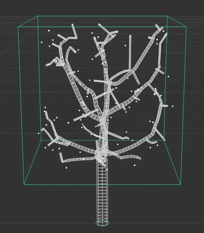
Object Type set as Wireframe.
This mode also cannot be rendered, but again offers a very fast and efficient viewport display.
With the default Display settings, the green line represents the trunk, the blue lines are the primary branches and the white lines are the secondary branches.
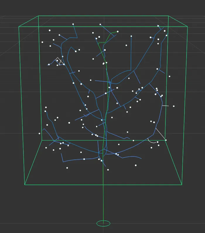
Object Type set in Line mode.
Spline Object
Section titled “Spline Object”Displays your tree as a Spline Object, in Object Type, which can be rendered.
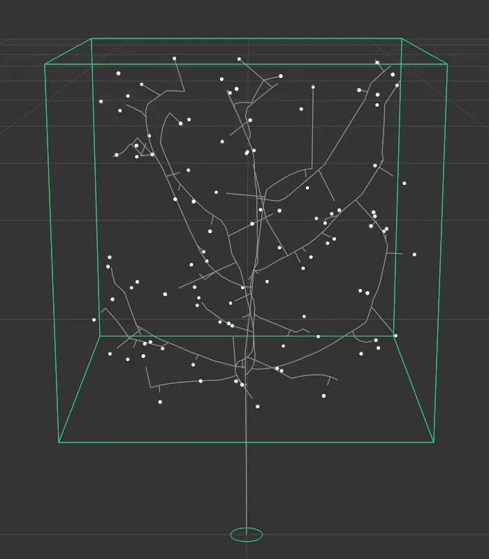
Object Type set as Spline Object.
Polygon Object
Section titled “Polygon Object”By default, the Object Type is set to display the tree as a Polygon Object.
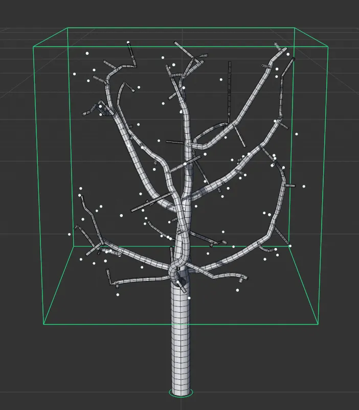
The default setting, Object Type set as Polygon Object.
Meshing Type
Section titled “Meshing Type”There are two Meshing Types: Intersect and Joined.
Intersect
Section titled “Intersect”This is the default setting; branches will merely intersect with the trunk.
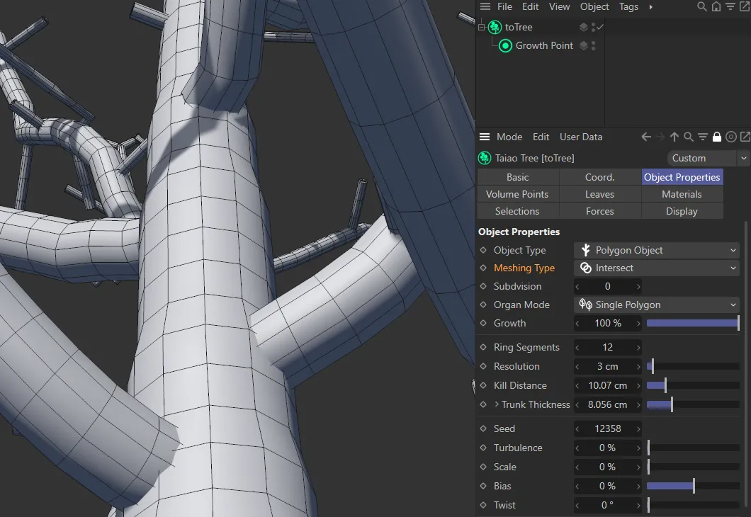
Meshing Type set to Intersect.
Joined
Section titled “Joined”The layers are joining, using more polygons, creating a detailed, cleaner, continuous mesh.
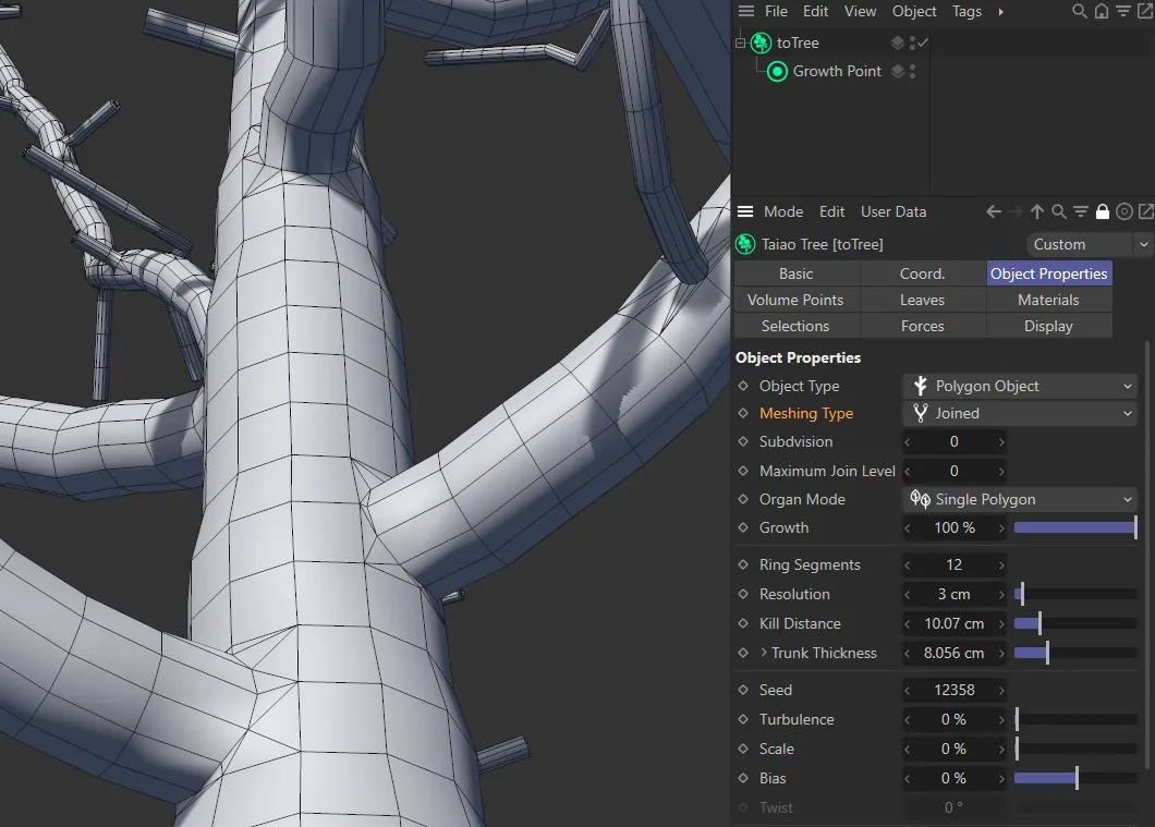
Meshing Type set to Joined.
Subdivision
Section titled “Subdivision”Adds subdivisions; the higher the setting, the more subdivisions there will be and the cleaner, and more detailed, the mesh will become, especially where there are joins.
Subdivision set to 0 (zero).
Subdivision set to 1.
Subdivision set to 2.
Maximum Join Level
Section titled “Maximum Join Level”Maximum Join Level option is only available when the Meshing Type is set to Joined.
At the default setting of 0 (zero), every layer of the plant, in the hierarchy in the Plant Layers tab, is joined.
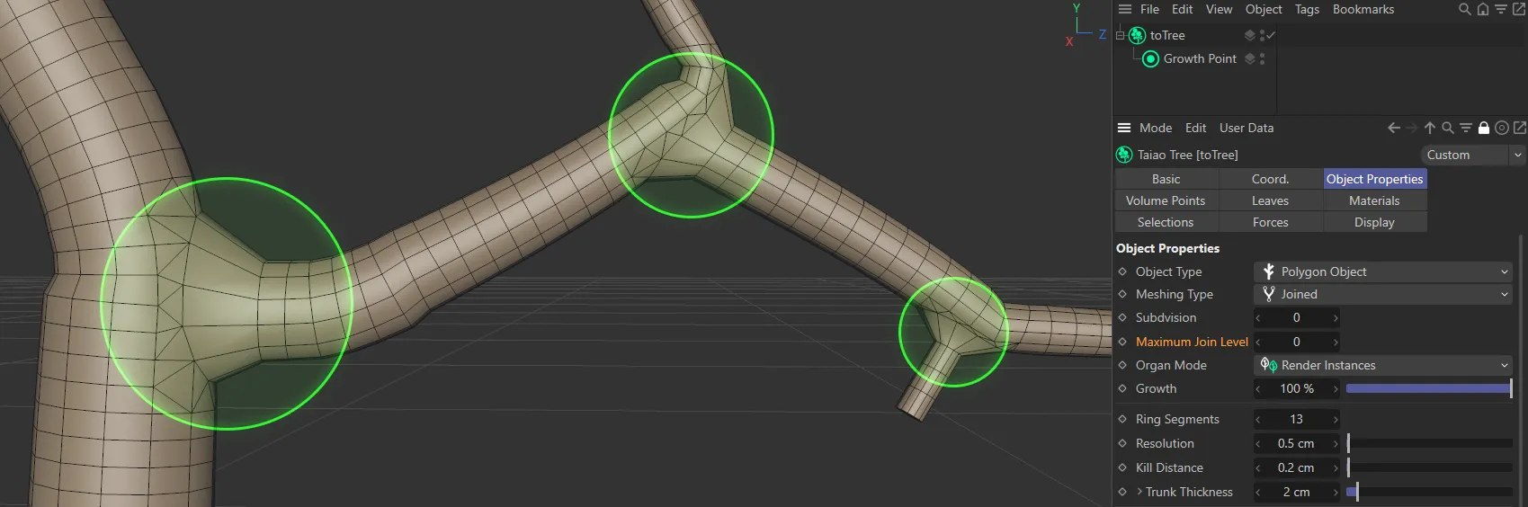
Maximum Join Level value set to 0 (zero).
If you change this setting to level 1, your first plant layer (the trunk) will be joined to the next (the branch); the other layers will be left to intersect.
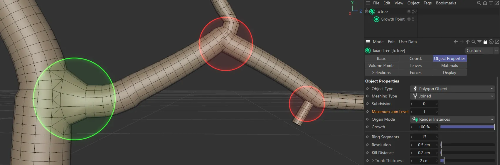
Maximum Join Level value set to 1.
At level 2, everything will be joined up to, and including, the second level.
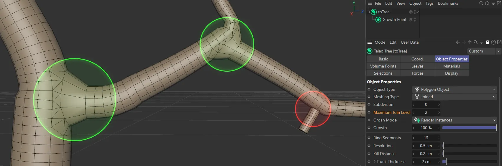
Maximum Join Level value set to 2.
At level 3, everything will be joined up to, and including, the third level.
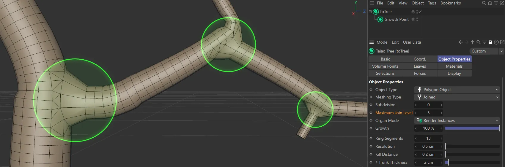
Maximum Join Level value set to 3.
This will continue, dependent on how many levels/layers you have in your plant.
Organ Mode
Section titled “Organ Mode”There are four settings, which dictate how the organs (leaves) are generated: Polygons, Single Polygon (the default), Render Instances and Multi-Instances.
Render Instances
Section titled “Render Instances”A much more efficient way of producing the organs, with one polygon object created and all other organs being instances of that one object.
Polygons
Section titled “Polygons”Generates an individual polygon object for each organ.
Single Polygon
Section titled “Single Polygon”All of the organs, as a whole, are represented by one polygon object.
Multi-Instances
Section titled “Multi-Instances”Another efficient setting, with one reference object for the organ, then one multi-instance for all of the other organs.
Growth
Section titled “Growth”This slider is at 100% by default, as the plant is 100% grown.
At 0 (zero) % your plant will not have begun to grow and all values in between represent their level of percentage growth.
This can be used with keyframes, to develop animation in your scene.
Animation to demonstrate the effect of the Growth slider.
Ring Segments
Section titled “Ring Segments”You can add more ring segments, giving your trunk and branches a more rounded profile.
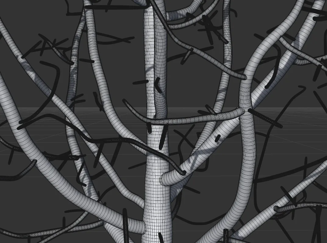
Resolution
Section titled “Resolution”The Resolution setting determines the number of height segments.
At the default of 5cm, there will be a segment every 5cm. Lowering the number will give you more polygons.
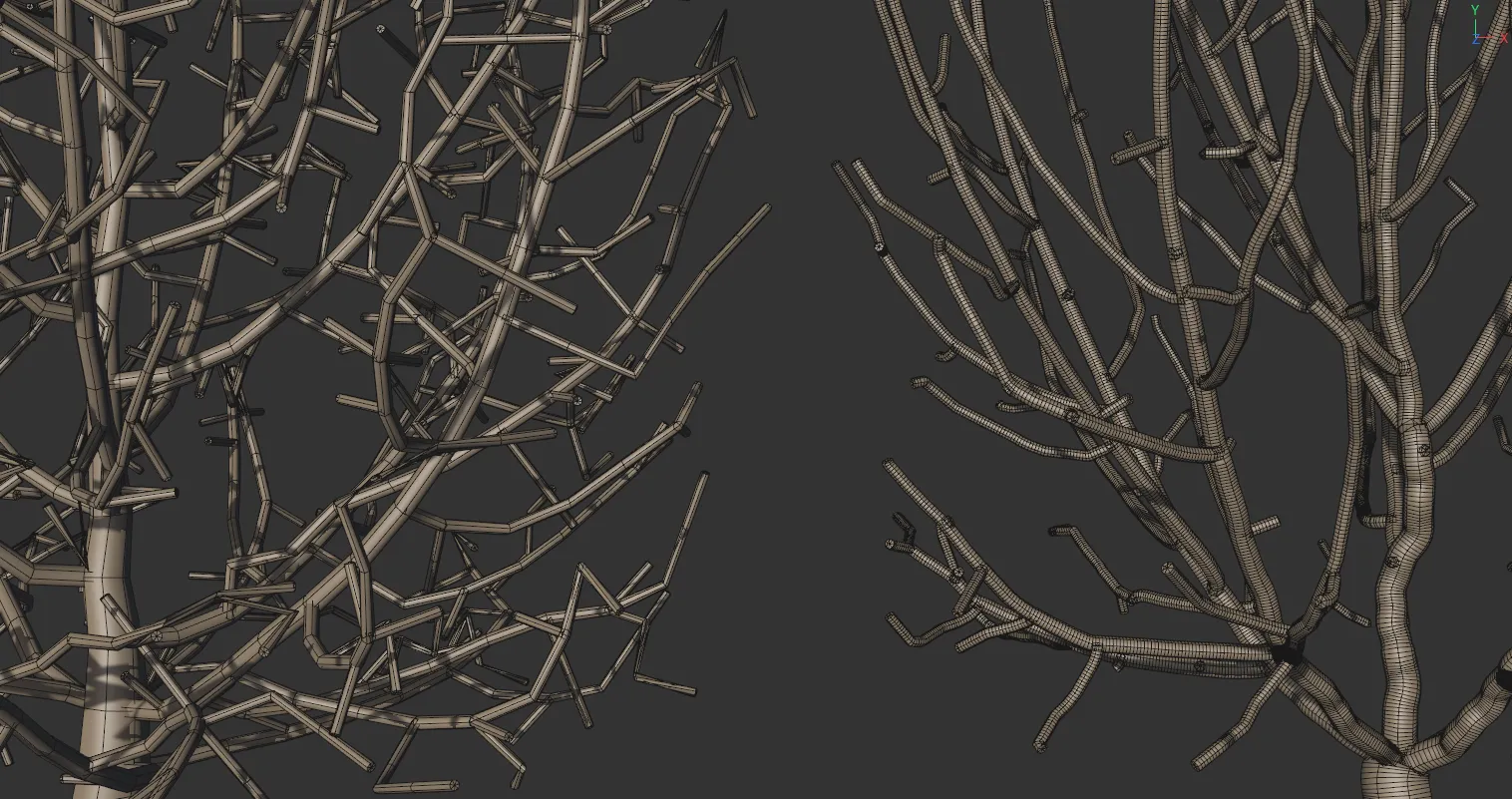
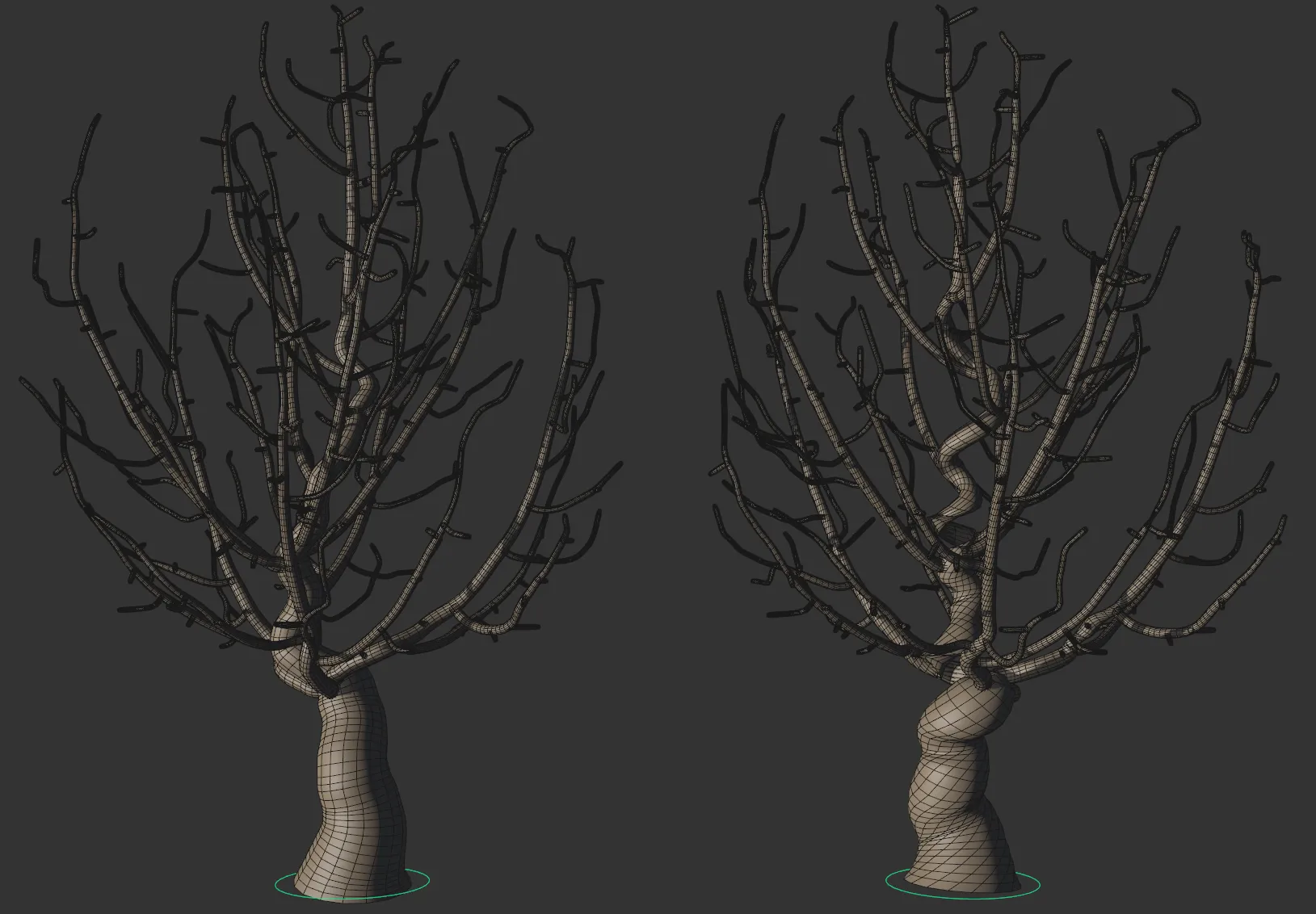
The tree on the left has Resolution set at 10cm, whilst on the right-hand tree it is set at 0.5cm.
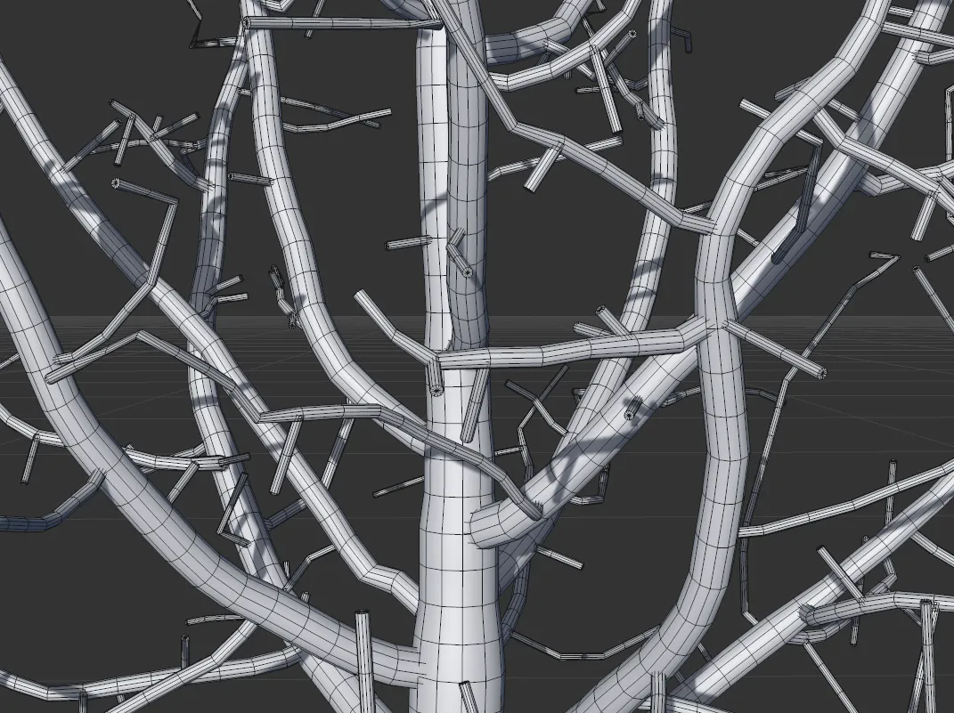
Kill Distance
Section titled “Kill Distance”This setting kills off unused attraction points (within the set amount) making them non-viable.
This helps to ensure that the geometry of the branches within the crown mesh is clean and not erratic.
The lower the setting, the more branches you will get in your scene.
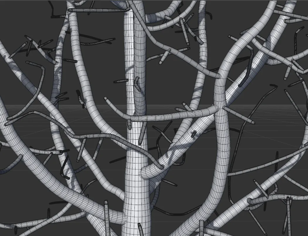
Raising this, to a larger Kill Distance value, will result in fewer branches.
It is good practice, for your design (because of how the algorithm works), to ensure that the Kill Distance value is at least twice the amount of the Resolution setting.
This will encourage better topology in the generation of the branches.
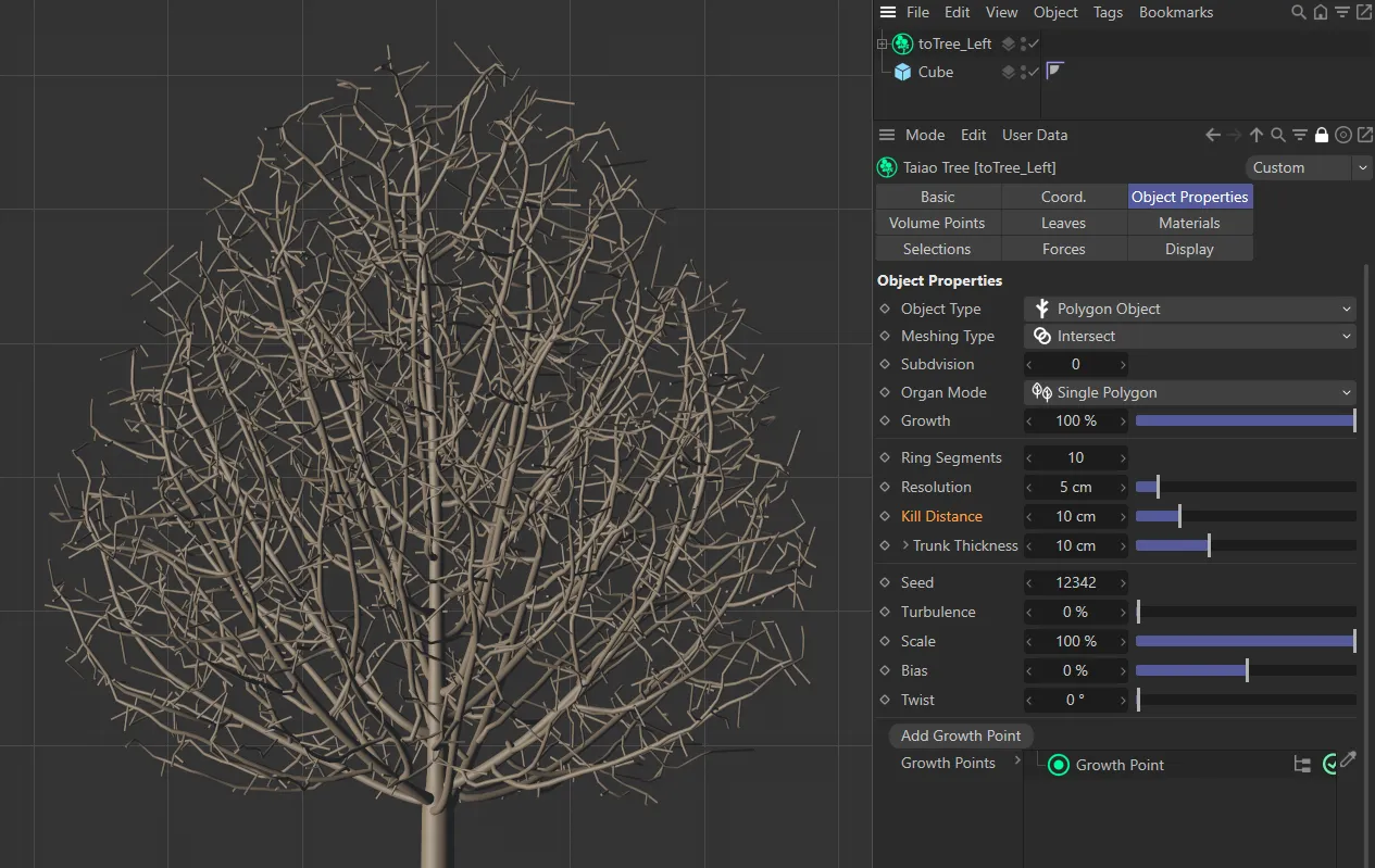
Kill Distance set to 1cm, generating a substantial amount of primary and secondary branches.
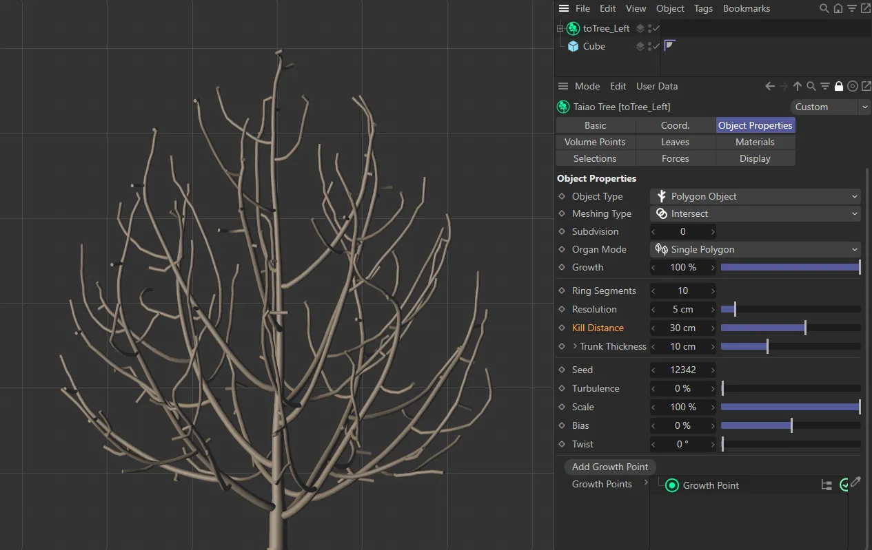
This image shows a tree with identical settings to the one on the left, except the Kill Distance setting, which is increased to 10cm, restricting the number of branches generated.
Trunk Thickness
Section titled “Trunk Thickness”Adjusts the size of the trunk.
Clicking on the drop-down arrow will give you falloff settings.
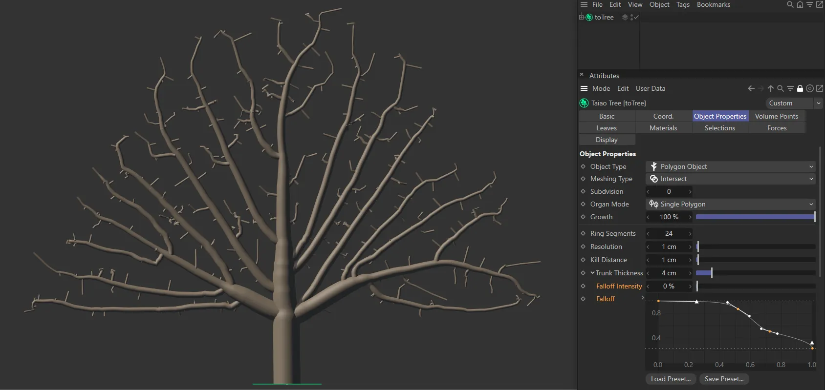
Falloff Intensity
Section titled “Falloff Intensity”Set at 80%, by default, this slider controls how the thickness of the layers falls off over their length.
Changing this to 0 (zero) % results in zero falloff, so the layers each retain their thickness level throughout their life.
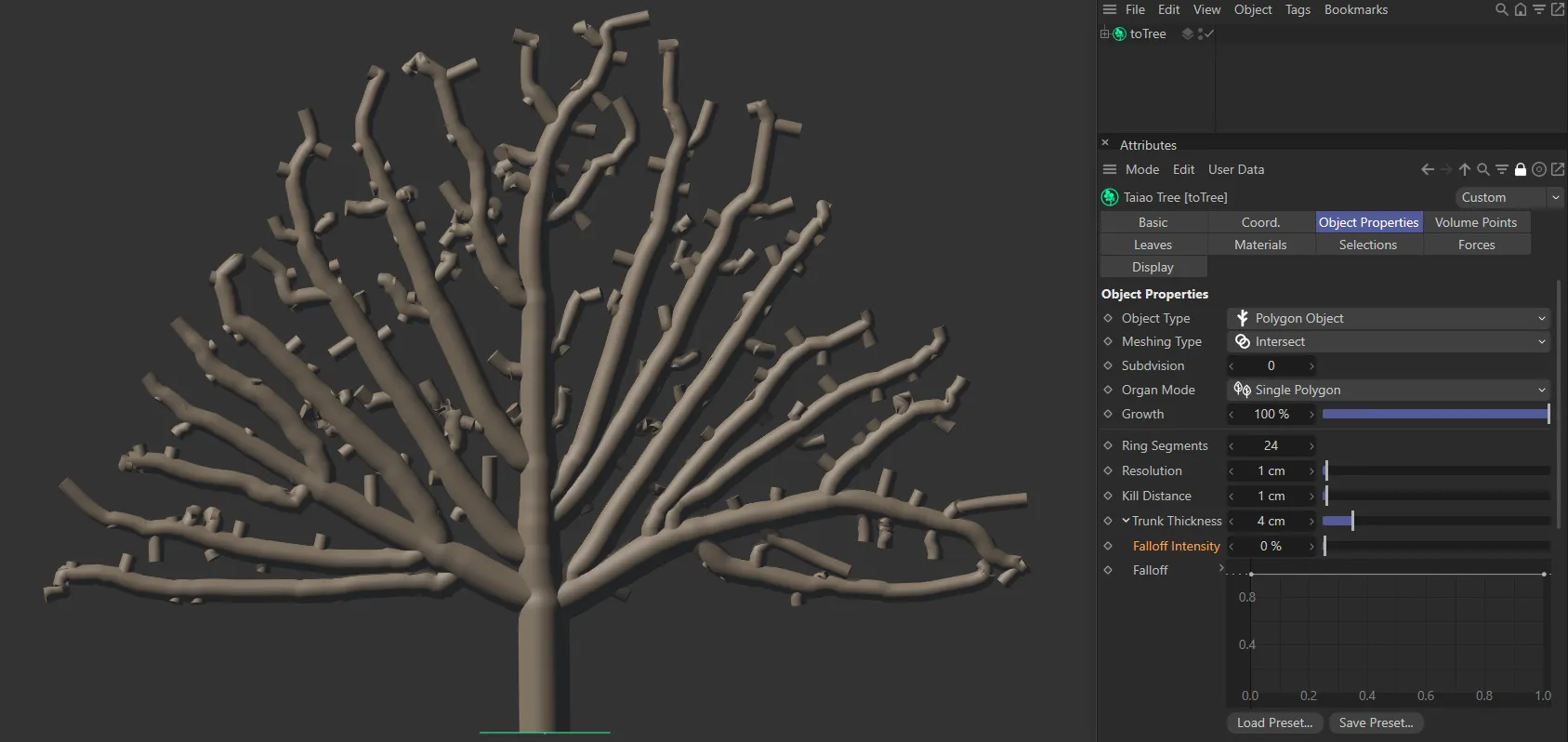
Falloff Intensity value of 0 (zero) %, with the Falloff curve at maximum from the trunk base to the tips of the branches.
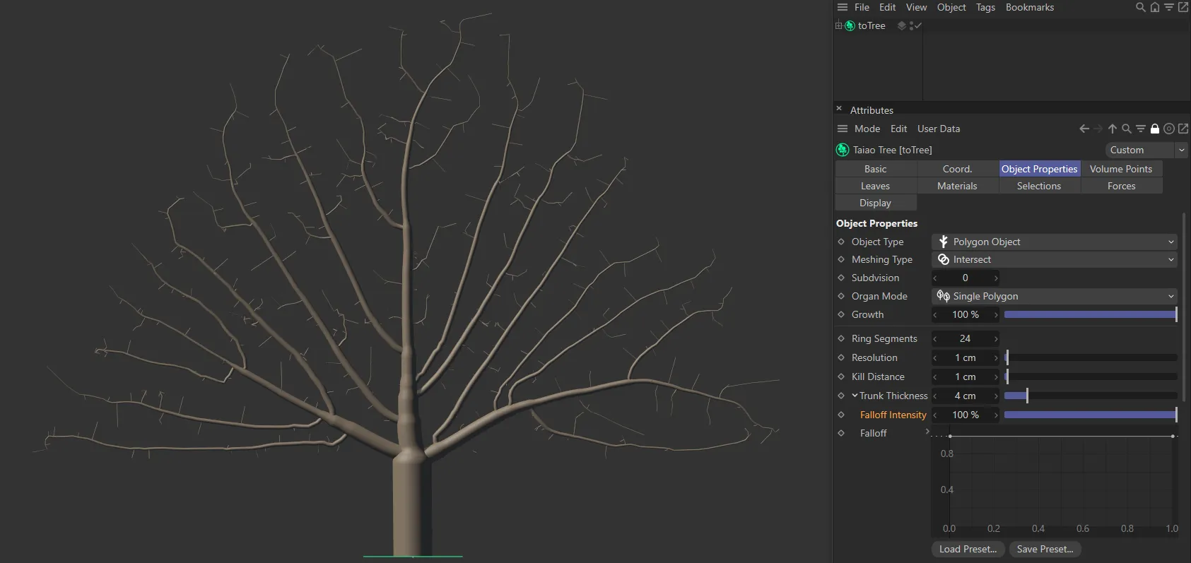
With the same Falloff curve setting, a Falloff Intensity of 100% changes the look entirely, with trunk and branches tapering off to a very narrow radius.
Falloff
Section titled “Falloff”The falloff is a multiplier for the radius of the trunk, from root to tip.
Used in conjunction with the Falloff Intensity setting, this spline curve can give you additional control of your tree’s proportions.
The left side of the X-axis represents the base of the trunk and the right side the tips of the branches.
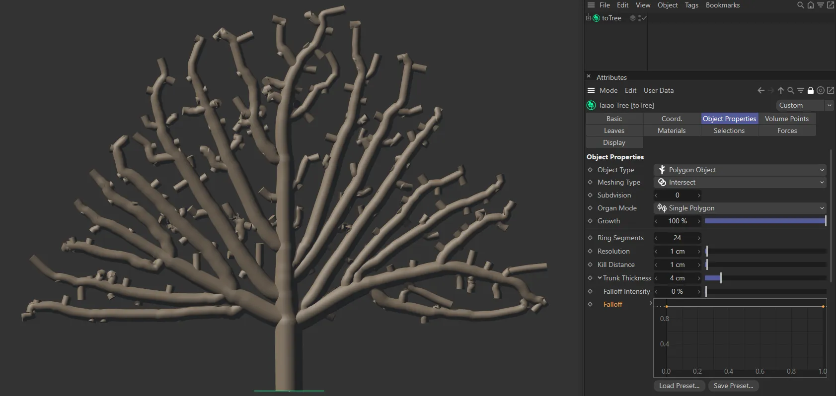
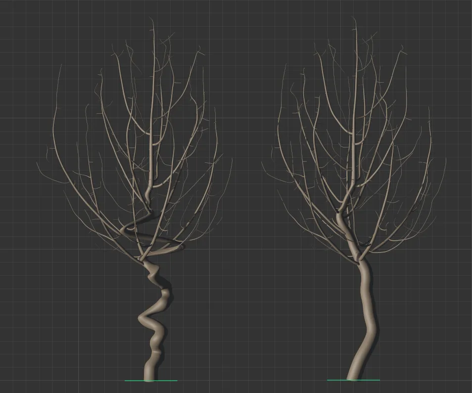
Falloff Intensity value of 0 (zero) %, with the Falloff curve at maximum from the trunk base to the tips of the branches.
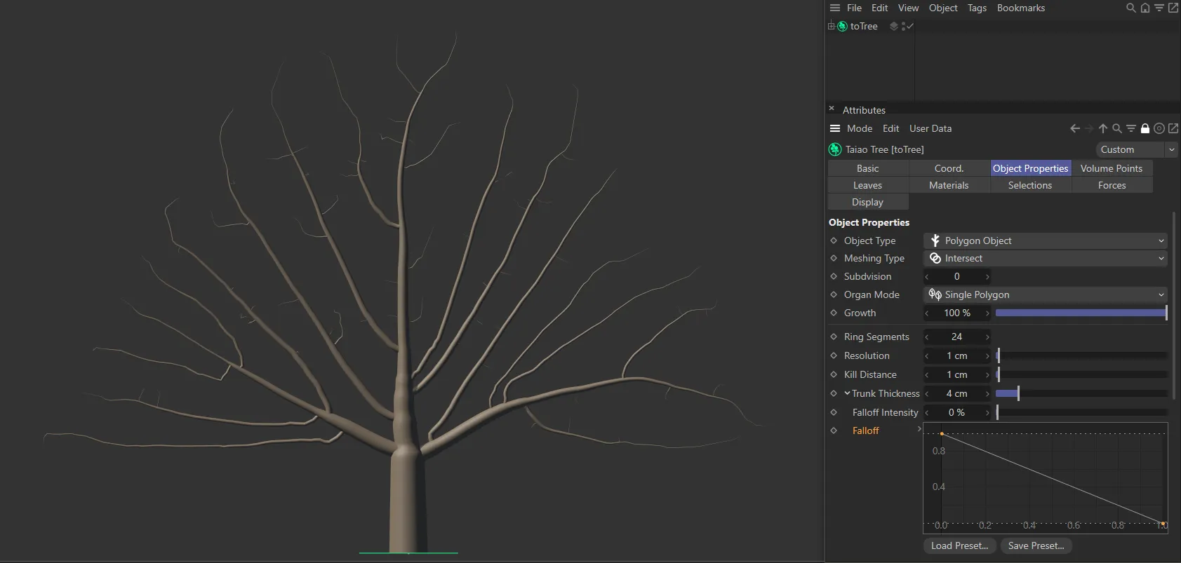
With the same Falloff Intensity value, this image shows the result of a linear Falloff spline, giving a different look to the image above.
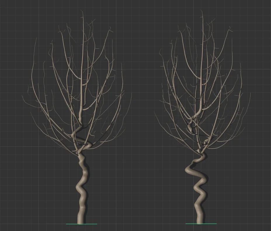
The Falloff curve can be used to customize the trunk profile, then the Falloff Intensity setting can further refine the thickness falloff, as in the images below.
A Falloff Intensity setting of 0 (zero) %, together with a customized Falloff spline setting is driving this look.
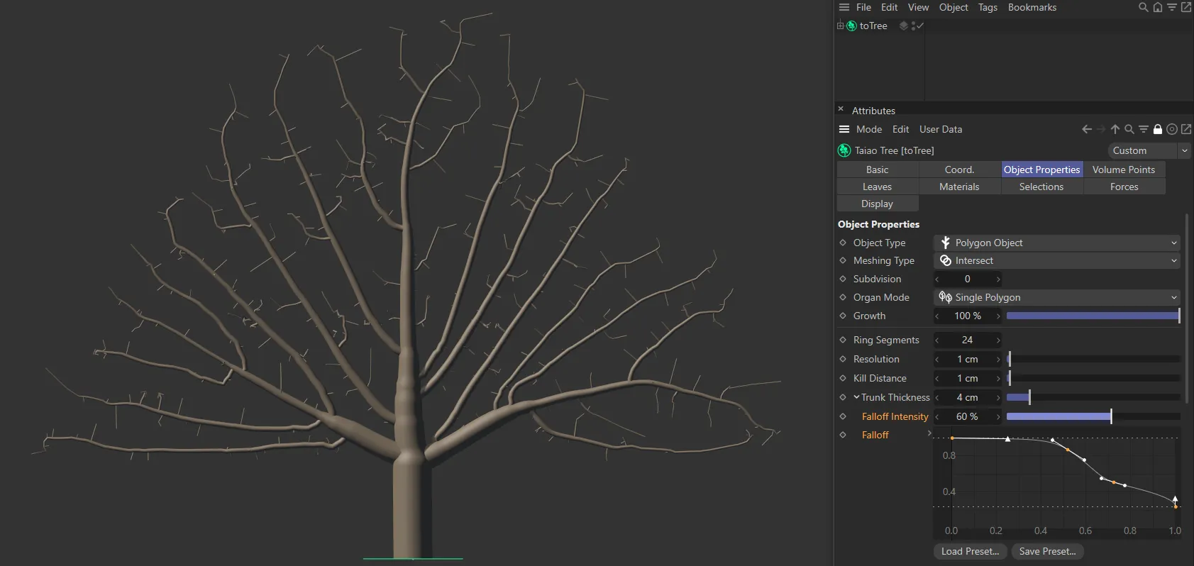
In this second image, the same Falloff spline setting is used, together with a Falloff Intensity of 60%, creating thinner branches.
Changing the Seed value will give you a different, random, look.
Turbulence
Section titled “Turbulence”You will need to raise the Scale setting of turbulence, below, to see an effect. Increasing the amount of turbulence will increase the deformation in your tree.
The tree on the left has a Turbulence value of 150%, while the one on the right is increased to 300%.
This controls the scale of the Turbulence setting.
Reducing the scale gives a finer noise definition.
The tree on the left has 4% Scale set, while the tree on the right is set at 30%. Both trees have an identical Turbulence value, making it clear that the smaller Scale setting results in a tighter deformation.
The Bias setting allows you to control where you want the deformation to take place.
At 0 (zero) % the bias is equally spread across the whole tree.
Below zero, the turbulence will be concentrated in the lower half of the tree and a positive bias targets the top half of the tree.
Raising this value will twist the tree around.
Twist set at 180 degrees on the left and raised to 2500 degrees on the right.
Add Growth Point
Section titled “Add Growth Point”By default, there is one growth point set as a child with toTree, visible as a green circle at the base of the tree.
Selecting Add Growth Point will give you an additional tree, which will branch towards the same attraction points, fighting for available space within the crown mesh.
None of the branches will intersect because of the way in which the algorithm works.
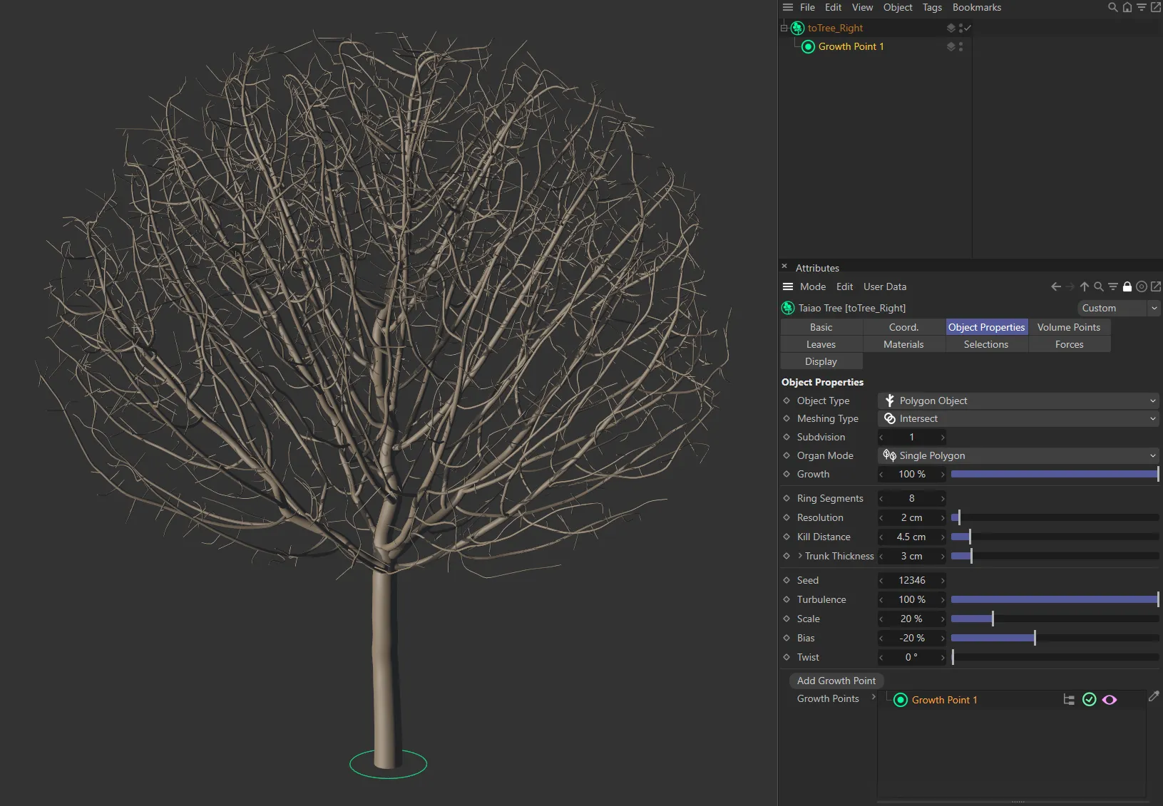
One growth point (shown as a green circle) in the scene, creating one tree.
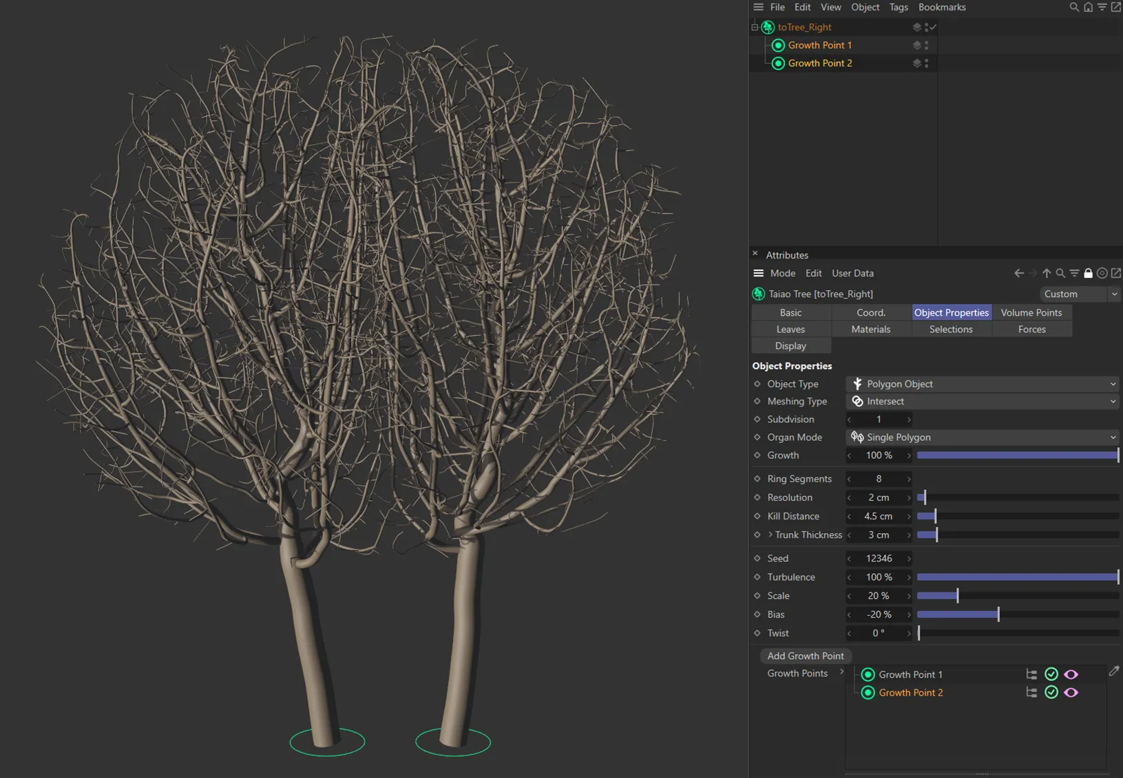
There are two growth points in this image, resulting in two trees, with different settings applied.
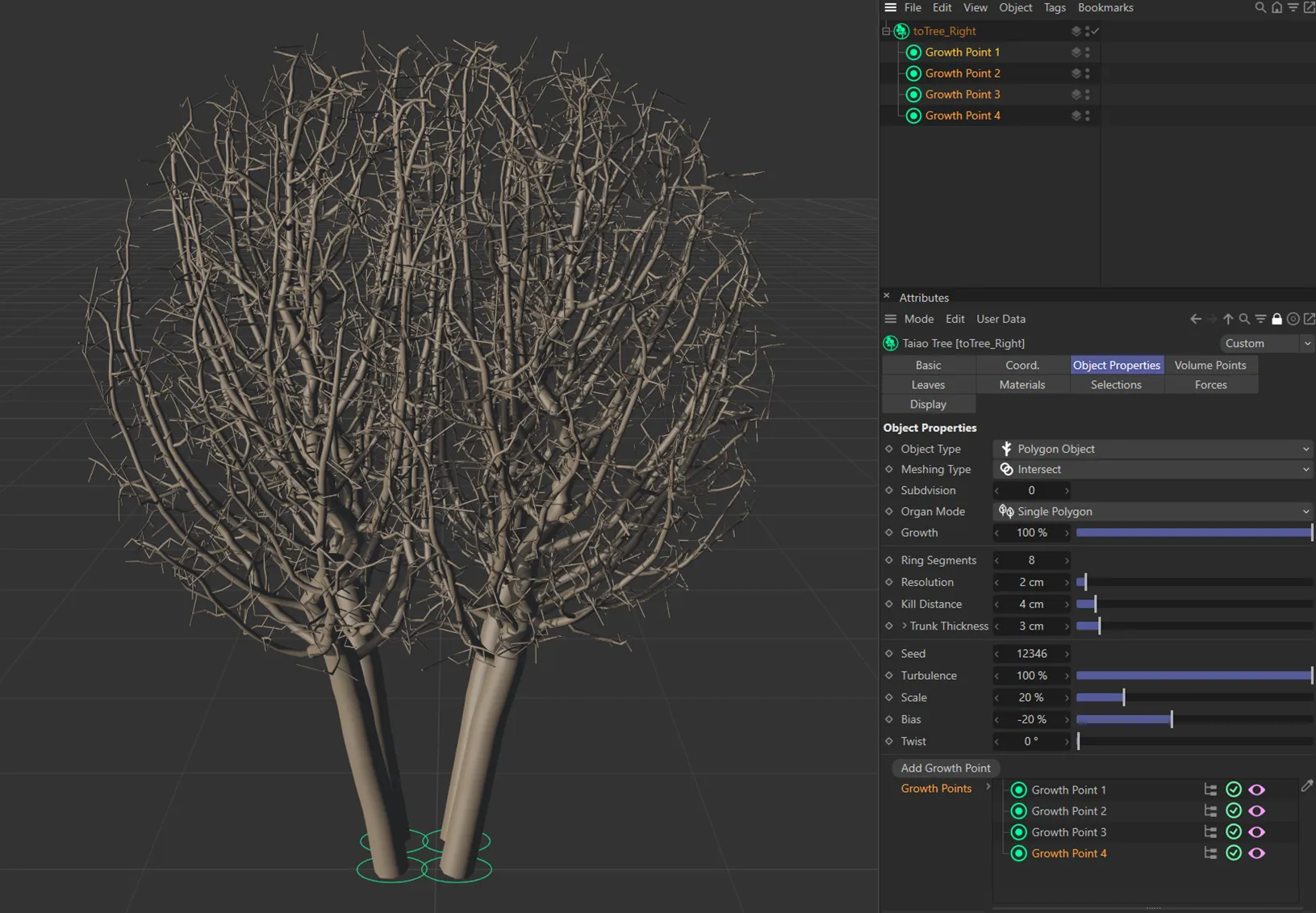
In this final image, there are four growth points, generating four trees.
In the viewport there are additional settings:
Clicking on the pink ‘eye’ icon will turn off the growth point in the viewport.
The green tick in a circle will disable the growth point, if clicked, turning into a red cross, as a result.
Finally, the red Hierarchy icon, when switched off, ensures that only the parent layer is a growth point.
This can be switched on to work with additional growth points when they are set as a child of another in the hierarchy, so that they all function as growth points.
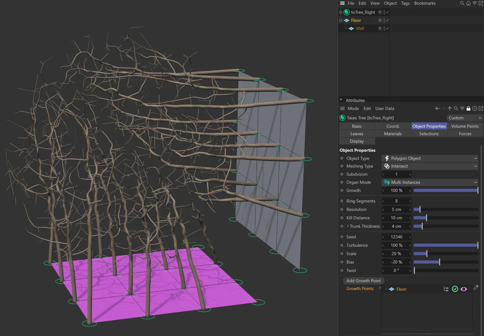
Only the Floor plane object has been linked in the Growth Point link field. Because the Hierarchy button is enabled, the vertex points from both the Floor and Wall objects are acting as growth points.
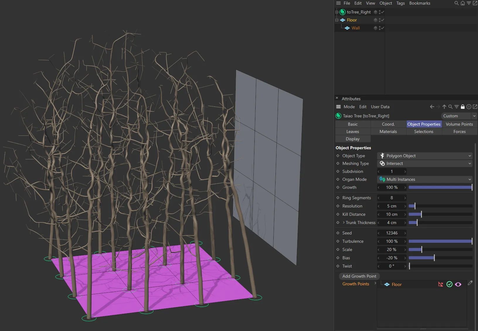
Conversely, in this image, the Hierarchy button is disabled (displayed in red), so only the vertex points from the Floor object are acting as growth points.
It is also possible to drag an emitter into this link field to use as a growth point.
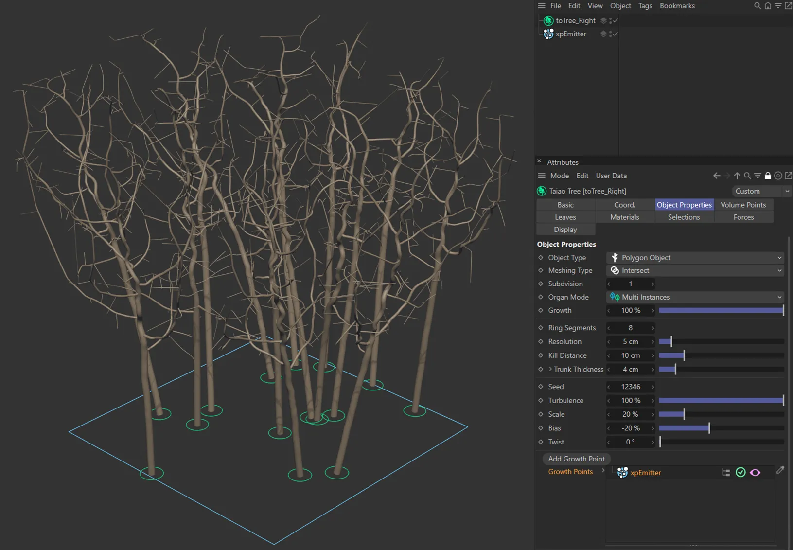
An xpEmitter with the Emission mode set as *Shot (*with a Shot Count of 15), has been linked in the Growth Points link field. A growth point is generated in the location of each particle as a result.
Root Flares
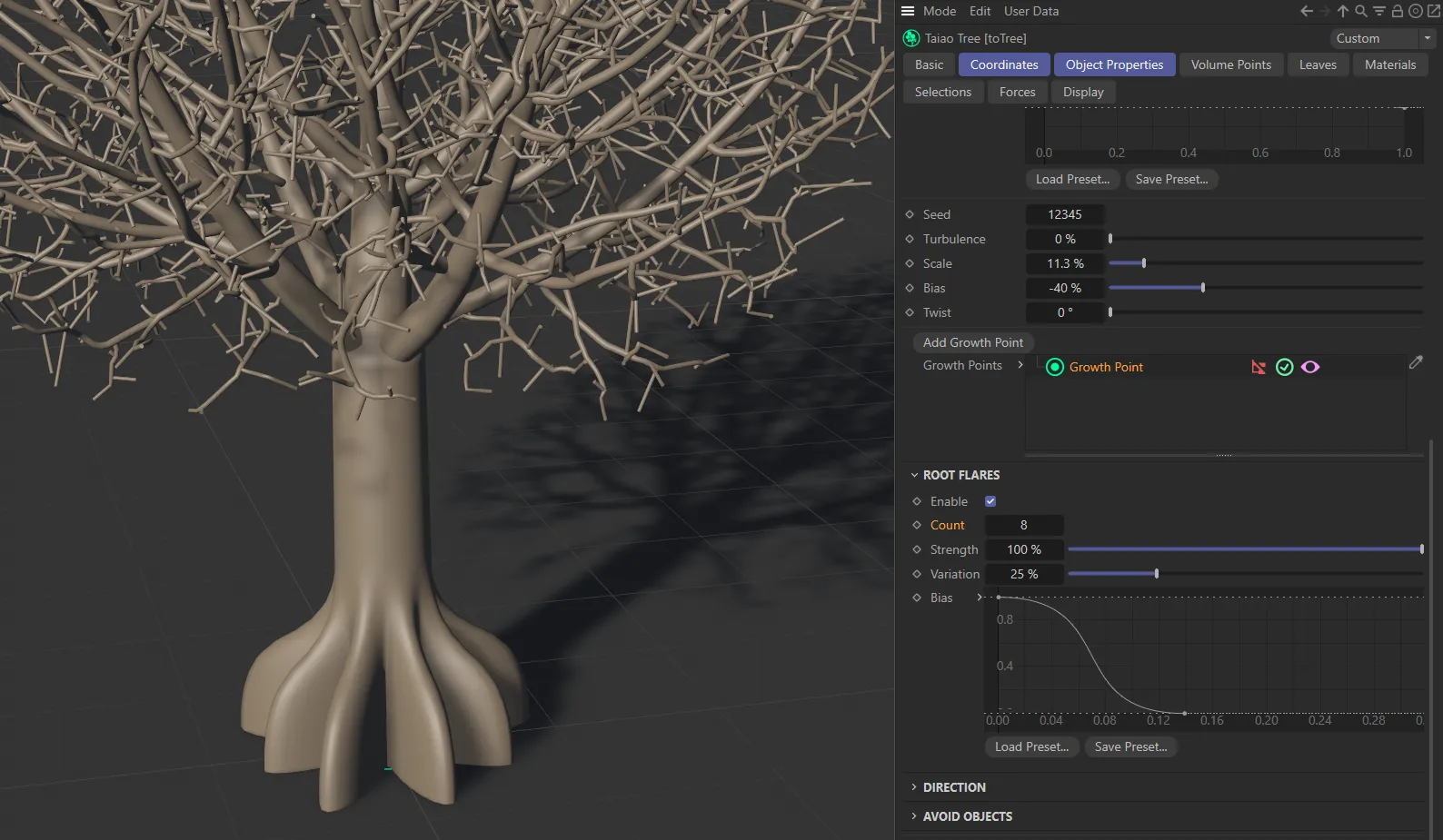
Section titled “Root Flares”These settings flare out the roots of your trunk.
Enable
Section titled “Enable”Clicking this box will enable flaring.
Set to 4 by default, but can be lowered or raised, as required.
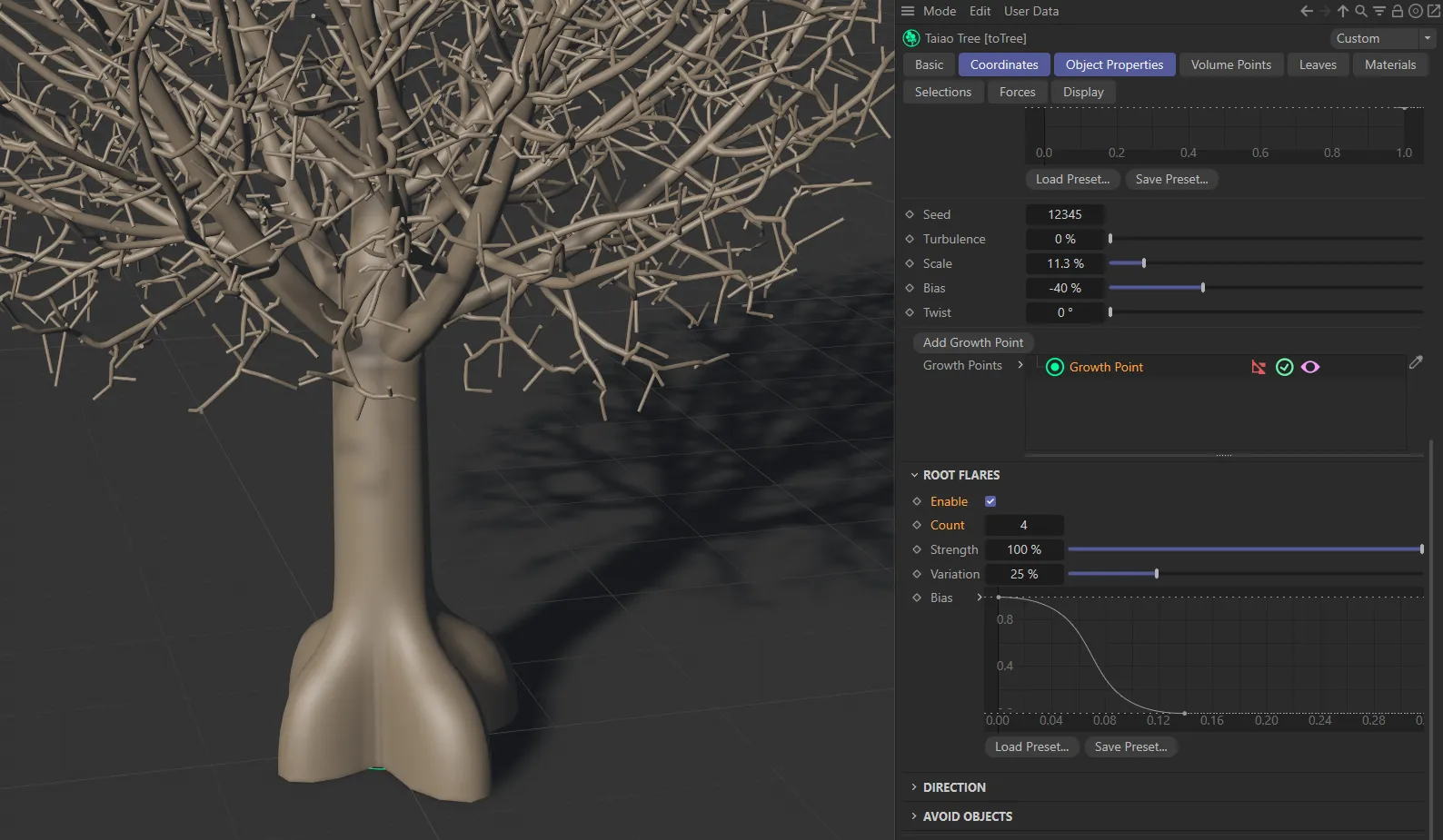
Root flares Count at 4.
In this second image, there are eight root flares, with the Count set at 8.
Strength
Section titled “Strength”Lowering this reduces the flaring all the way to 0 (zero) %, where there is no flaring at all.
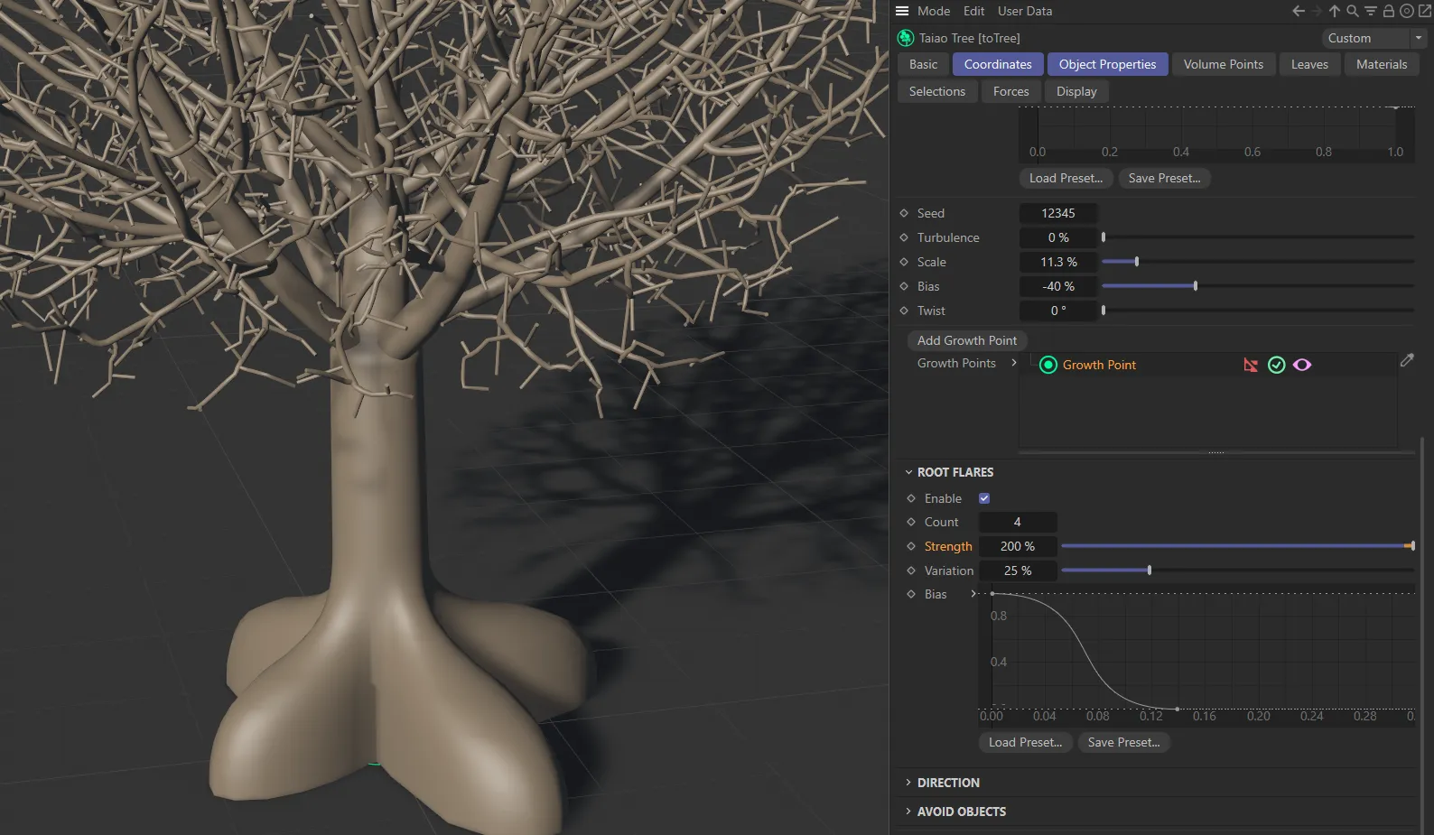
In this image, the Strength, of the root flares, is raised to 200%.
Variation
Section titled “Variation”This setting will vary each root’s flare strength.
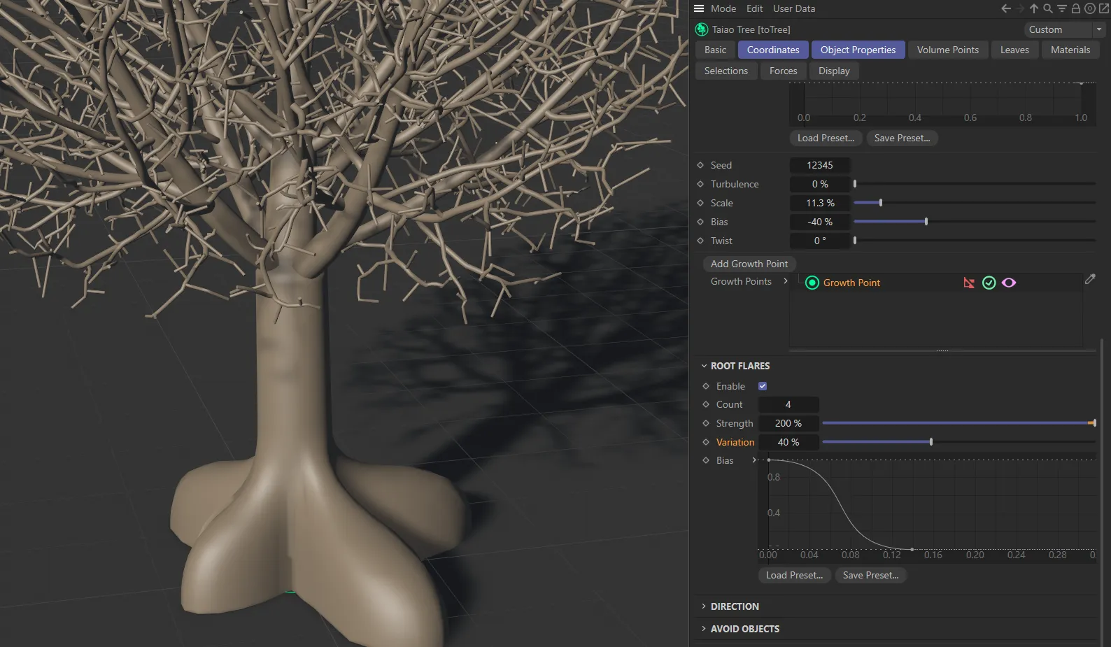
With the same settings as above, except the Variation raised to 40%.
The Bias setting can be altered using a spline curve.
The X-axis starts at the base of the trunk and moves up to the top.
The Y-axis controls the amount of flaring, mapped to the Strength percentage setting.
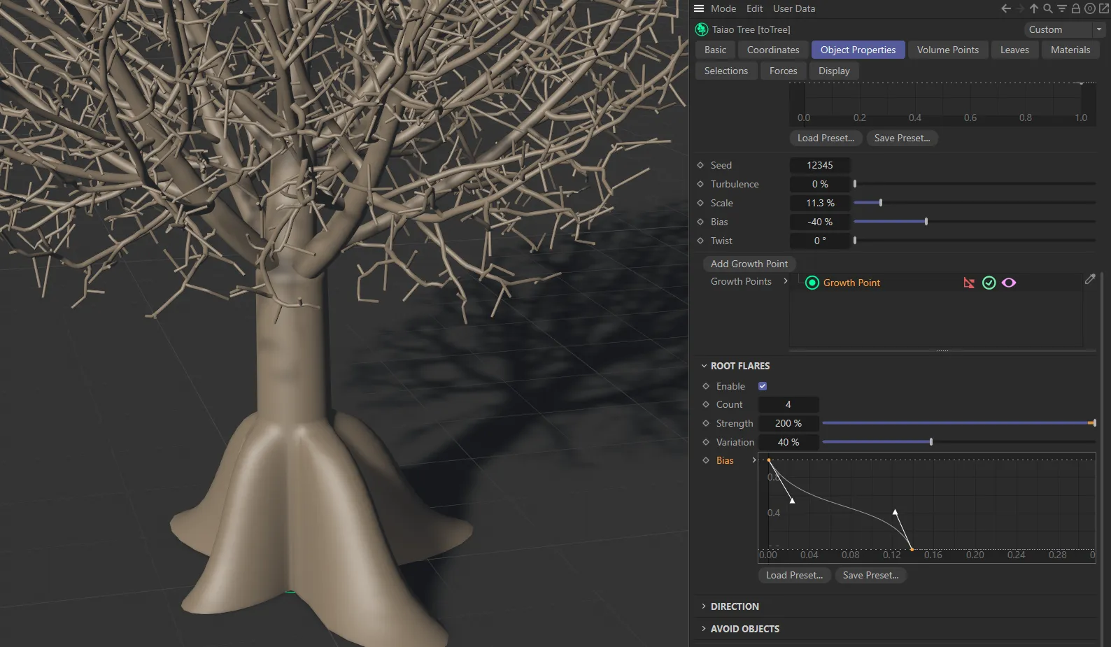
The root flares, in this image, mimic the Bias spline curve, with 40% Variation set between them.
Direction
Section titled “Direction”It is possible to get your tree to grow towards scene objects, by using the Direction settings.
Grow Towards
Section titled “Grow Towards”Dragging and dropping your object into this link field will encourage your tree to grow in the direction of this object, wherever you have placed it in the viewport.
Attraction Strength
Section titled “Attraction Strength”Raising this value will raise the level of attraction towards the object that you have put into your Grow Towards link field.
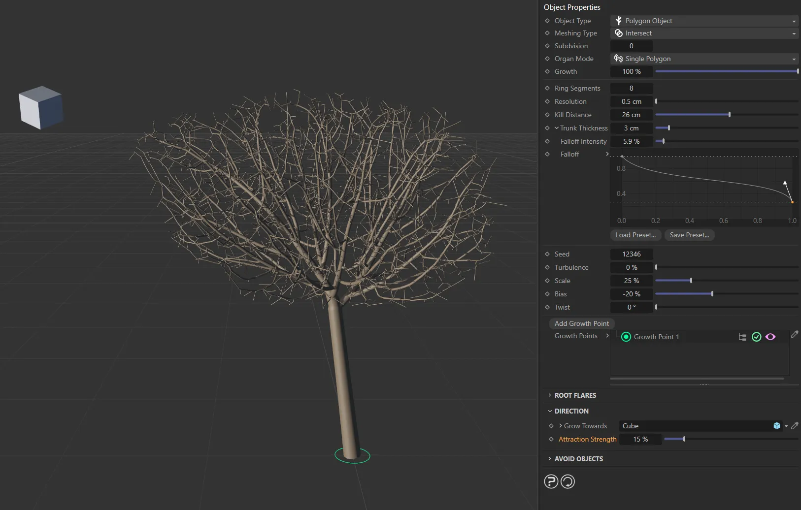
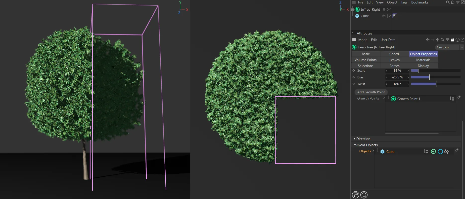
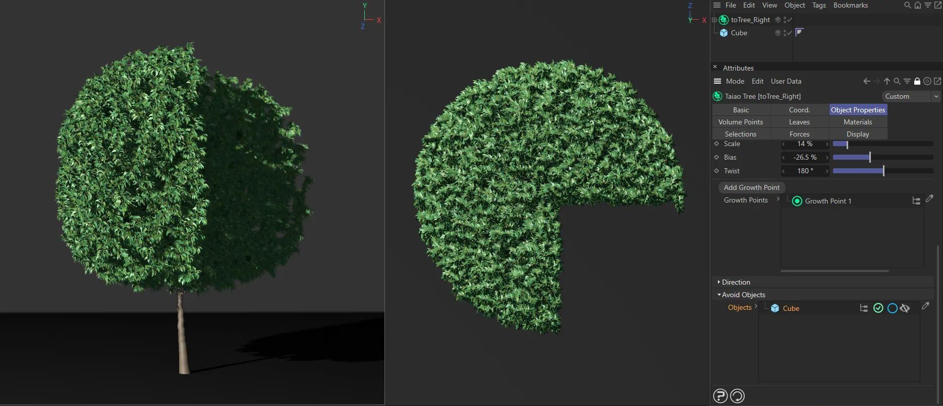
Tree growing towards a Cube with 15% Attraction Strength setting.
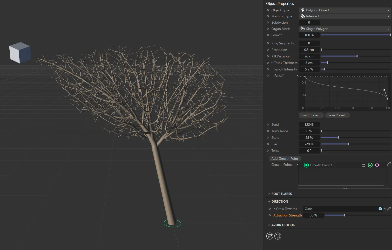
Tree growing towards a Cube with Attraction Strength set at **30%.
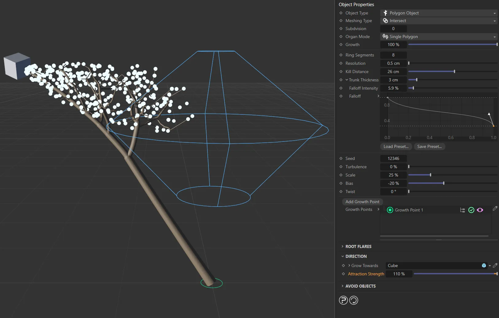
Image to demonstrate the Attraction Strength slider and the effect of exceeding the 100% value, drawing the tree through the boundaries of the Crown Mesh boundary box towards the Cube, which has been dropped into the Grow Towards link field.
Avoid Objects
Section titled “Avoid Objects”Objects
Section titled “Objects”You can set your tree to avoid scene objects, by dragging them into the Objects list.
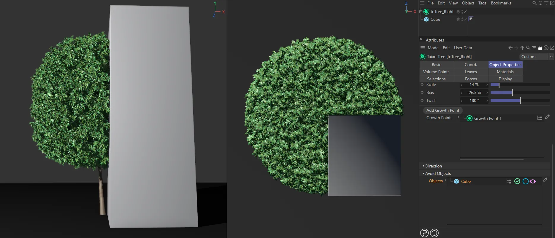
In this scene, the Cube in the Objects link field is being avoided by the tree. With the pink eye icon enabled, the Cube is visible.
Again, there are additional options available.
Clicking on the pink eye icon will turn the object invisible.
The same scene as above, with the pink eye disabled. By default, the display settings are now showing a pink wireframe Cube.
Once again, the same scene, this time with Object Wireframe disabled in the Display tab.
There are two different modes of how the Avoid Objects settings work.
To demonstrate this, the scene has been set up, in the images below, with two identical toTree rigs.
Both rigs have a cylinder positioned along the Z axis in order to ‘cut through the branches, by using the the Avoid Objects settings.
First, by default, any attraction points within the volume of the object will be culled. **
This mode can be identified by the blue circle icon in the Objects link field and is visible in the trees on the left of all three examples seen below.
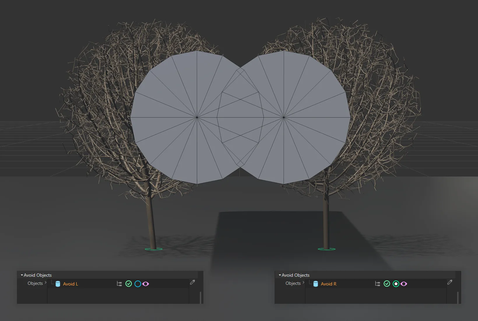
In this scene there are two toTree objects, each with a Cylinder that intersects all of the branches. The Cylinder is visible here.
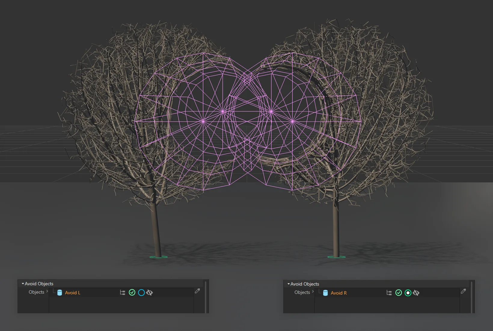
The Cylinder visibility mode has now been changed to just show the wireframe objects. The two toTree objects are clearly avoiding the Cylinders.
It is also possible to reactivate the attraction points within the object by clicking on the attraction points cull mode, blue/green circle in the Avoid Objects link field.
The tree itself will not be able to reach the attraction points, whilst still being attracted to them.
The result will be the tree growing more tightly around the scene object.
This mode has been attributed to the trees on the right side of these images.
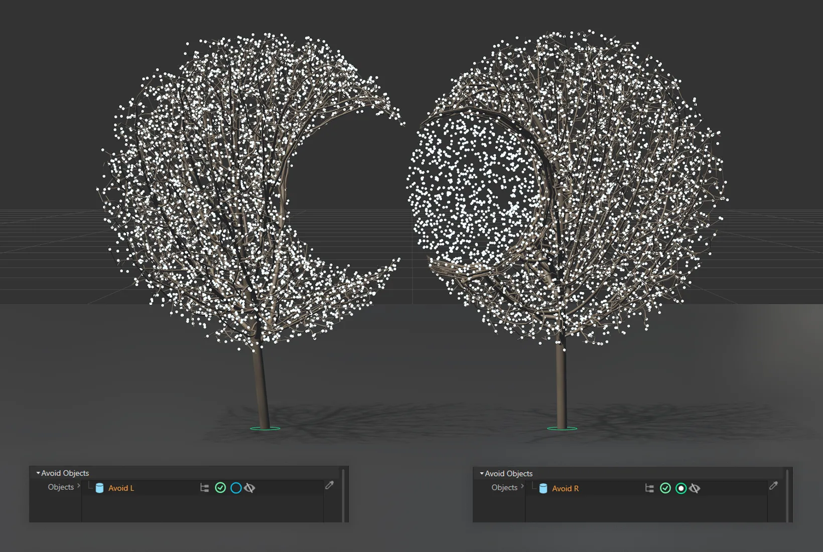
In this image, the Avoid Objects setting on the left is culling attraction points within the Cylinder object. Whereas, on the right, whilst the different setting still avoids the Cylinder object, there are still attraction points, which the tree is growing towards.
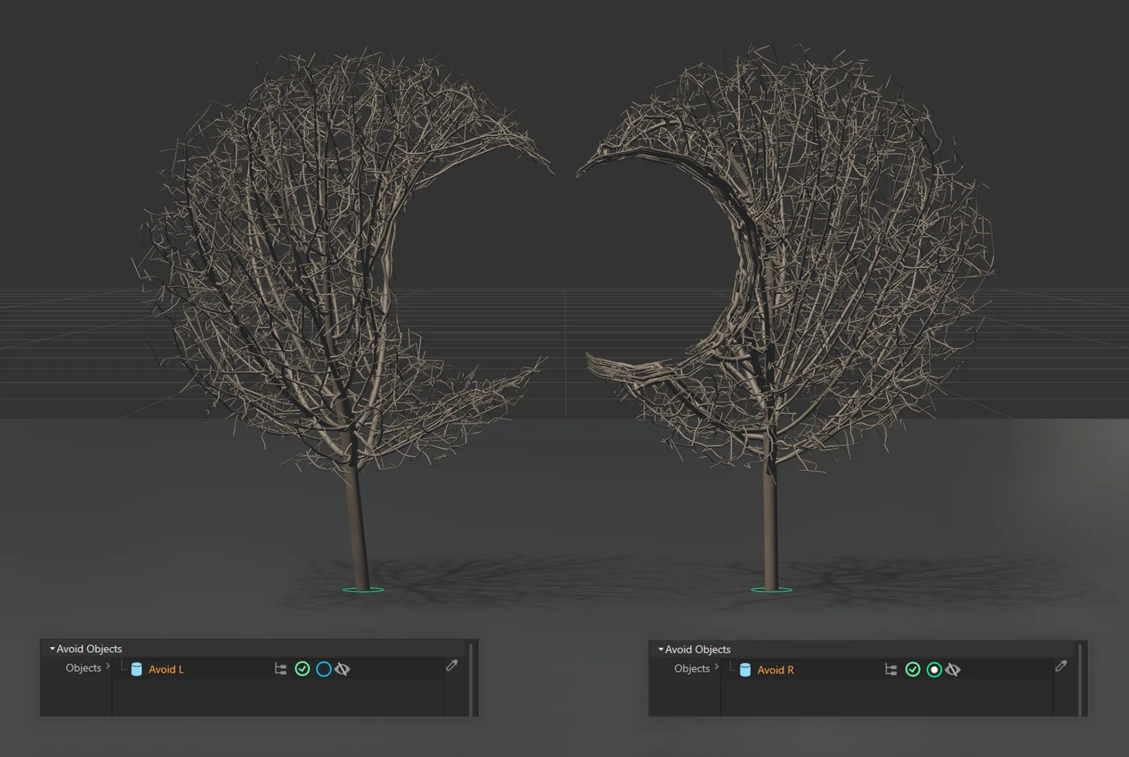
As in the image above (with the attraction points visible), in the result on the left, the branches cull as they meet the cylinder’s mesh.
On the right, with second mode activated, the attraction points still exist inside of the cylinder’s volume and therefore the branches are wrapping tightly to its surface.
Open Preset Browser
Section titled “Open Preset Browser”All objects now have an Open Preset Browser button to complement the menu option.
This will open the preset browser if it is not already open.
For further information on the Preset Browser, click the link below.
Copyright © 2026 INSYDIUM LTD. All rights reserved.