Trunk
From the Add Part drop-down box, you can select Trunk, which is added to the Objects Manager.
Highlighting it will reveal individual settings related to the Trunk layer, with three tabs: Main, Modifiers and Materials.
Main tab
Section titled “Main tab”Changing this value will give a new, random look, based on the other settings.
Height
Section titled “Height”Sets the height of the trunk.
Radius
Section titled “Radius”This sets the girth of the trunk.
Ring Segments
Section titled “Ring Segments”This option is set to 8, by default, and controls the number of segments around the trunk.
Raising this level will add to the polygon resolution.
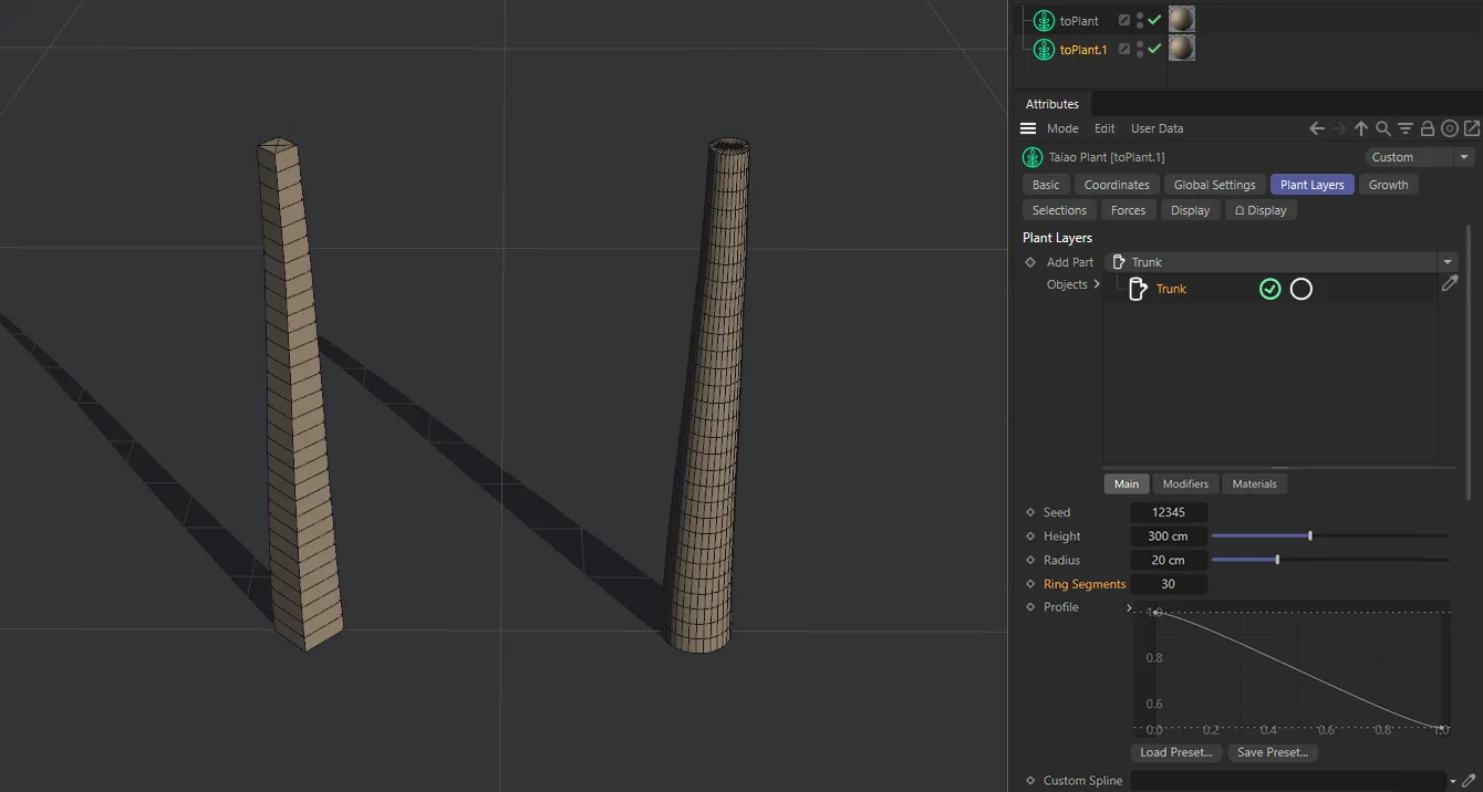
The trunk on the left has a Ring Segments setting of 4, while the trunk on the right has 30.
Until you do this, the segment height will be determined by the Segment Resolution level that is also set in the Global Settings tab.
Unchecking the Use Resolution box will reveal a separate option.
Segment Count
Section titled “Segment Count”When available, this will be set to 10, by default, and can be increased or decreased to control the number of ring segments in the height of the trunk, making it more or less detailed.
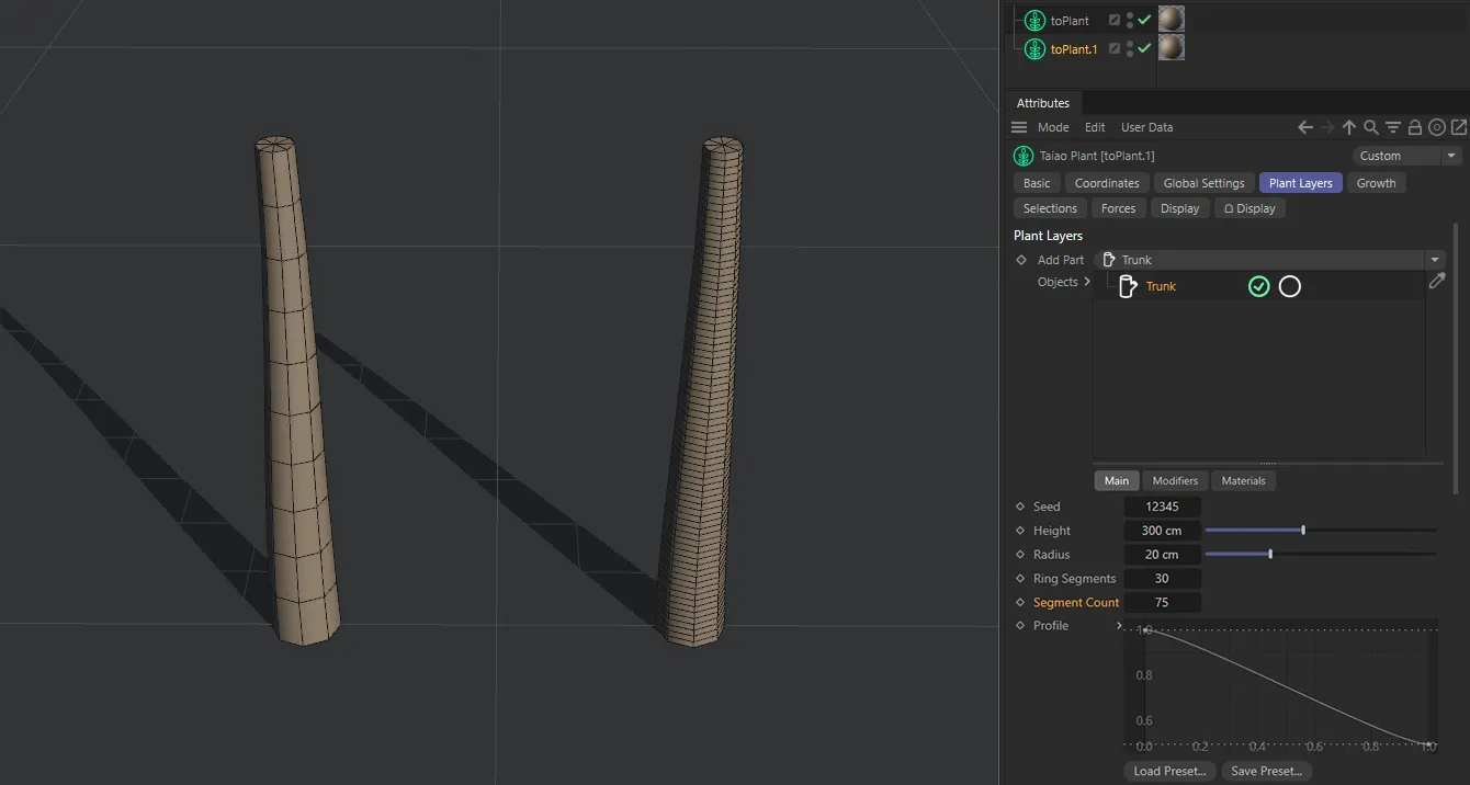
The trunk on the left has the default Segment Count setting of 10, while the trunk on the right has 75.
Profile
Section titled “Profile”Manually altering the profile spline curve will enable you to shape the trunk.
The X-axis is the length of the trunk from the bottom to the top and the Y-axis controls the Radius value.
Animation to demonstrate manipulation of the Profile spline curve to alter the shape of the trunk.
Custom Spline
Section titled “Custom Spline”There is the facility to introduce a custom spline to create a shape, as seen below.
Dragging this spline into the Custom Spline link field will result in the spline shape being used to create the trunk.
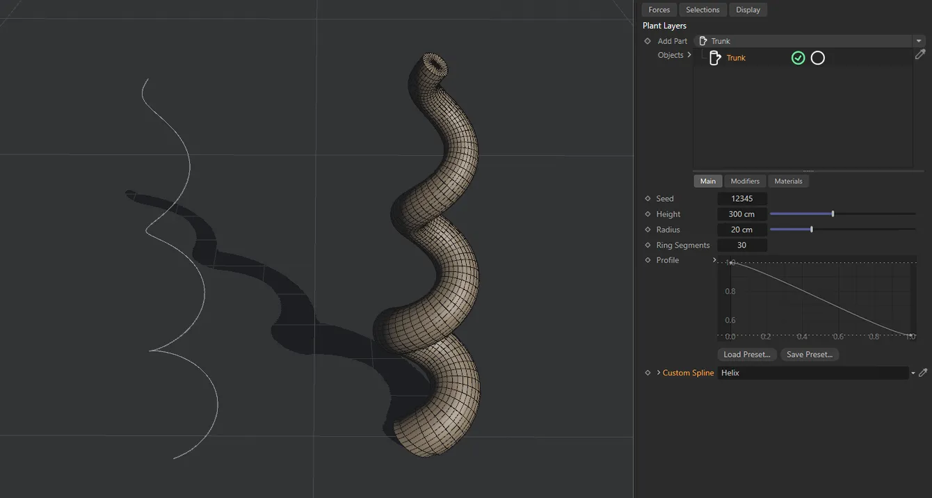
The result of the Helix spline being dragged and dropped into the Custom Spline link field.
The Ring Segments value can then be customized, as before, but the Segment Count setting for the height has been determined by the spline’s intermediate points.
This can be altered by highlighting the spline in the Objects Manager and looking in the Object tab, where the Intermediate Points are set to Uniform, by default.
There are different settings available here: None, Natural, Adaptive and Subdivided, which will all have different effects on the distribution mode of your trunk.
Modifiers tab
Section titled “Modifiers tab”Modifier
Section titled “Modifier”These settings give you the ability to deform and twist your trunk.
The available Modifier types are: Furling, Turbulence, Twist, Root Flares, Gravity, Aim, Profile and Displacer.
Each comes with its own parameter settings.
Modifier Stack
Section titled “Modifier Stack”The hierarchical list of modifiers affecting your Trunk layer.
The modifiers each come with Blend and Strength settings in common.
Set as Normal, by default, the slider controls the intensity of the modifier, blending its effects with the effects of any other modifiers that you have in the scene.
Setting it to 0 (zero) % will eliminate any effect the modifier might have.
Setting it to 100% will show the full effect.
The other options are: Min, Subtract, Multiply, Max and Add.
Normal
Section titled “Normal”In Normal mode, there is no blending happening.
The hierarchy in the Modifier Stack determines which modifier is being enabled, with the last in ‘the tree’ overriding the ones above it.
Analyzes the modifiers and uses the lowest value for each point to give the result.
Subtract
Section titled “Subtract”In this mode, the value of the modifier is subtracted from the value of the one above it.
Multiply
Section titled “Multiply”Here, the modifiers’ values are multiplied and the results give the deformation.
Analyzes the modifiers and uses the highest value for each point to give the result.
This mode takes the values from a modifier and adds them to the values of others in the scene to give the result.
Strength
Section titled “Strength”Increasing or decreasing the level on the Strength slider will raise or lower the strength of the modifier highlighted, allowing any other modifier in the scene to be apparent.
Furling modifier
Section titled “Furling modifier”The Furling settings mimic the natural curling that can occur in plants as they grow.
Animation to demonstrate the effect of increasing the Angle, to bend the trunk, and also changing the Bias, to alter where on the trunk the furling begins.
Angle, Variation
Section titled “Angle, Variation”Increasing this slider will curl the trunk in one direction and decreasing it will curl the trunk in the other.
The Variation setting will apply variety between angles, should you have more than one Trunk layer in your scene.
Bias, Variation
Section titled “Bias, Variation”This dictates where on the trunk the furling takes place.
At the default setting of 50%, the trunk is furling from the middle.
Lowering the setting sets the furling beginning lower down the trunk and raising it has the opposite effect.
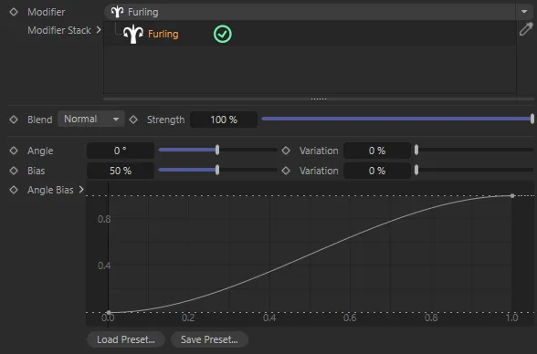
The Furling modifier UI, demonstrating the Angle Bias parameter (added with update 2024.2).
Angle Bias
Section titled “Angle Bias”This parameter (added with update 2024.2) simply acts as a multiplier to the existing bend angle along the length of the trunk.
Turbulence modifier
Section titled “Turbulence modifier”Changing the Seed value will give you a different, random, look.
Turbulence
Section titled “Turbulence”This slider controls the level of turbulence in your trunk.
Set at 0 (zero) %, you will have a perfectly straight trunk.
You can manually input a level higher than 100%, to add additional turbulence.
Animation to demonstrate the effect of the Turbulence slider, including settings over 100%.
This slider increases or decreases the scale of turbulence that you have set, with finer detail at a lower value setting.
Animation to demonstrate the effect of reducing the scale value to lower the turbulence scale.
Frequency
Section titled “Frequency”Sets the rate at which the turbulence animates.
At the default setting of 0 (zero) %, the entire trunk is affected by the turbulence.
At -100% there is no turbulence at all, then raising it will affect the trunk from the base upwards.
Over 0 (zero) %, the effect starts to occur towards the top of the trunk, with 100%, again, having no effect.
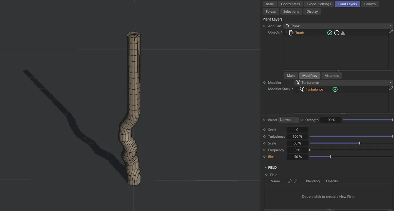
This image shows the effect of a Bias value of -50% on the lower half of the trunk.
Twist modifier
Section titled “Twist modifier”The twisting of the trunk is controlled by this slider.
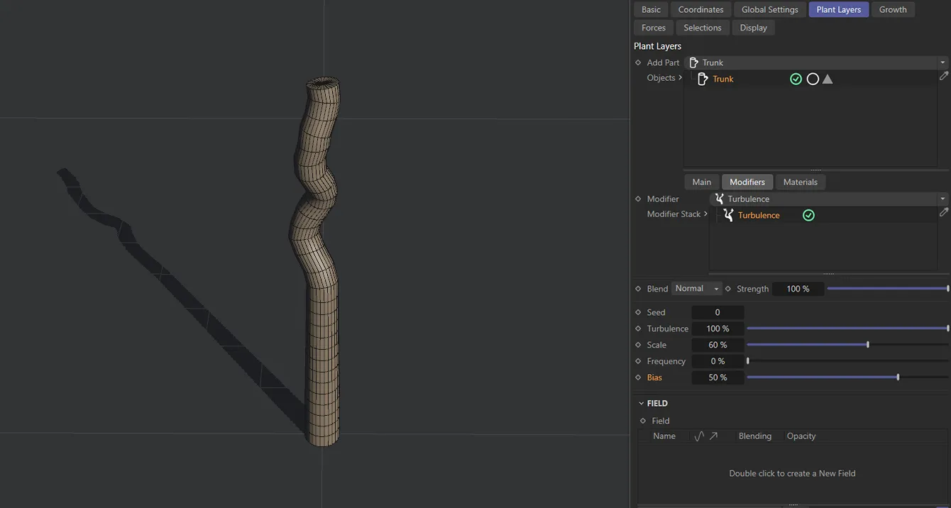
The Bias setting of 50% has this effect on the upper half of the trunk.
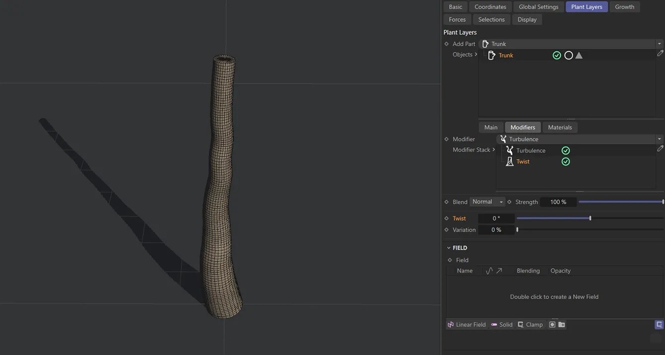
Twist setting of 0 (zero) %.
Variation
Section titled “Variation”Applies a degree of variation, should you have more than one Trunk layer in your scene.
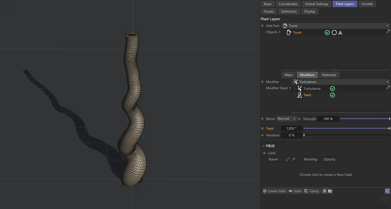
This trunk is subject to a Twist setting of 1205%.
Root Flares modifier
Section titled “Root Flares modifier”These settings flare out the roots of your trunk.
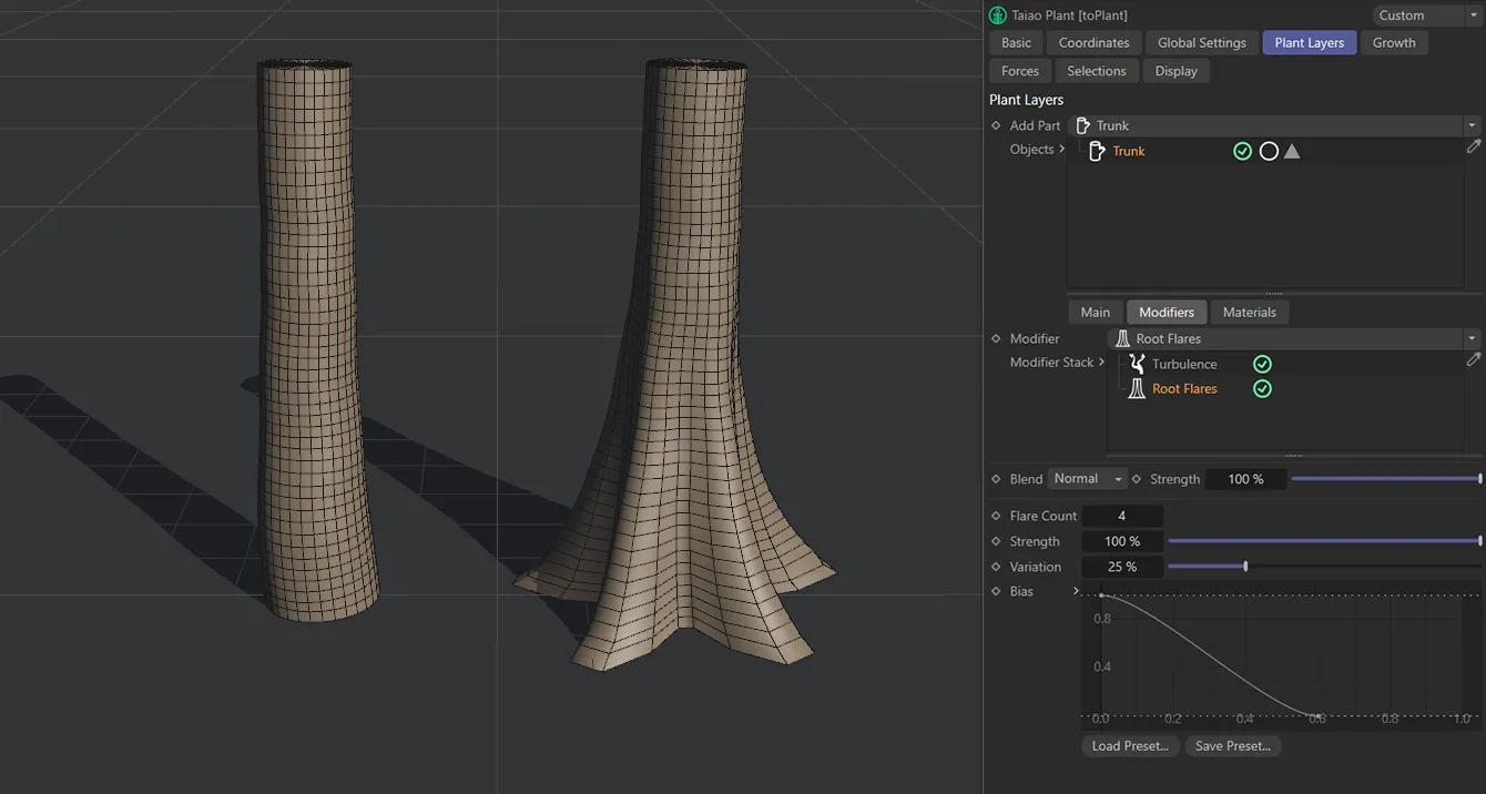
The trunk on the left has Enable Root Flares disabled, while the trunk on the right has it enabled.
Flare Count
Section titled “Flare Count”Set to 4 by default, but can be lowered or raised, as required.
Animation to show the effect of an increase in the Flare Count setting.
Strength
Section titled “Strength”Lowering this reduces the flaring all the way to 0 (zero) %, where there is no flaring at all.
Variation
Section titled “Variation”This setting will vary each root’s flare strength.
Animation to demonstrate the effects of increasing the Variation slider to randomly resize each flare.
The Bias setting can be altered using a spline curve.
The X-axis starts at the base of the trunk and moves up to the top.
The Y-axis controls the amount of flaring, mapped to the Strength percentage setting.
Animation to demonstrate the effect of the Bias slider.
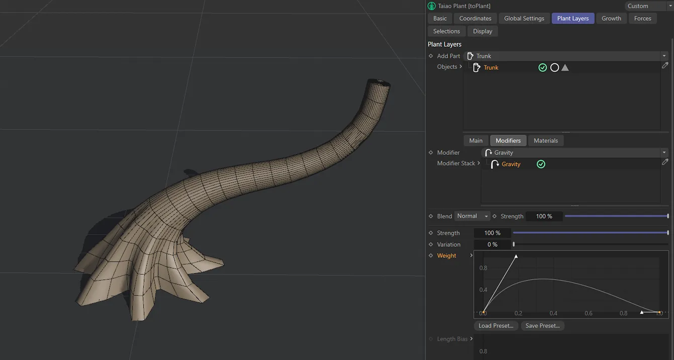
Gravity modifier
Section titled “Gravity modifier”These settings simulate the effects of gravity, as the trunk is growing.
It is important to note that the gravitational force always takes effect in the +X direction.
Strength
Section titled “Strength”Increasing this percentage will have a greater gravitational pull on the trunk.
Animation to demonstrate the effect of the Strength slider on the Trunk layer.
Variation
Section titled “Variation”This slider is most effective when you have multiple trunks in your scene and, by raising the slider, you will see a different effect on each trunk.
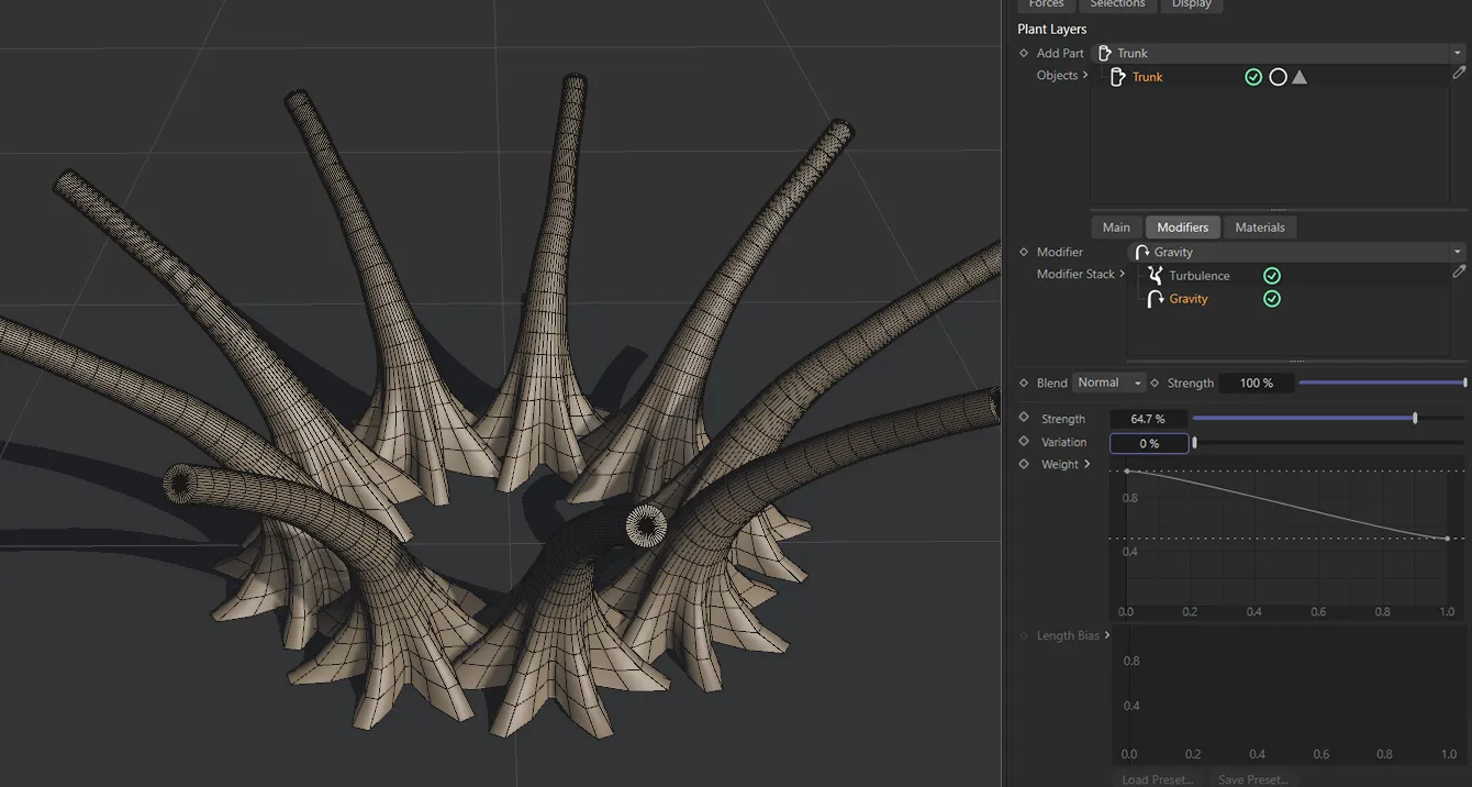
Variation is at 0 (zero) % here, with all trunks being affected by the same gravity Strength setting of 64.7%.
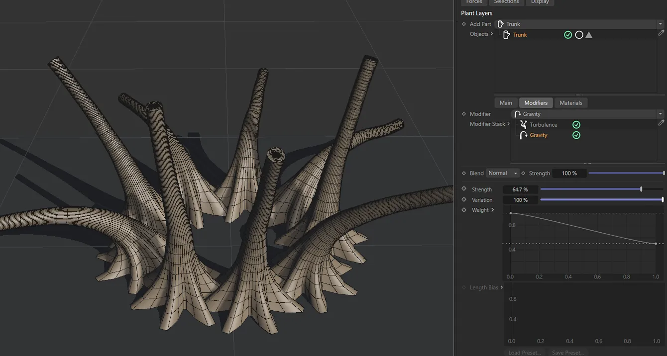
In this second image, the Variation setting is 100%, giving each trunk a completely varied amount of gravity up to the Strength value of 64.7%.
Weight
Section titled “Weight”This curve enables you to adjust the gravitational weight along the trunk.
The X-axis representing the length of the trunk and the Y-axis being the strength of the gravitational effect.
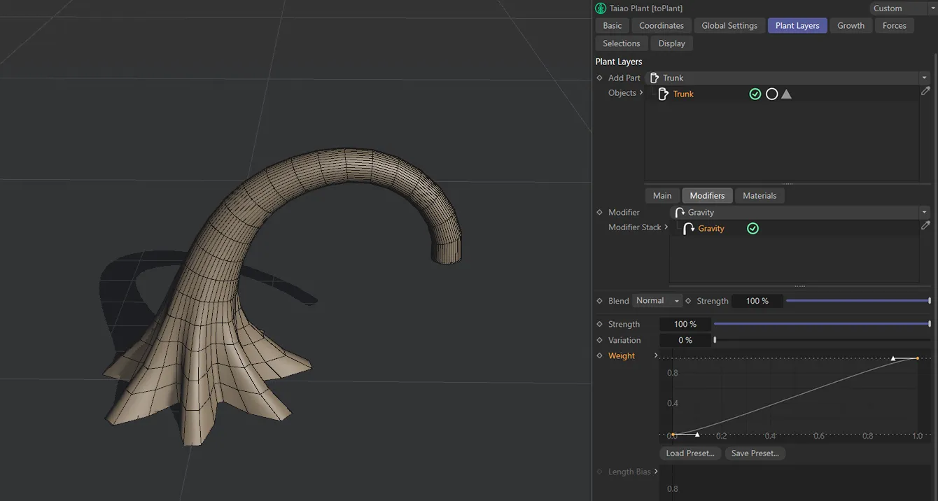
Here the Weight spline rises from 0 (zero) to 100 % on the Y-axis, resulting in rising gravitational strength as it climbs the trunk; the top of the trunk is at full strength.
This Weight spline produces 0 (zero) % gravity at both the base and the tip of the trunk, with 100% gravity affecting the lower section.
Aim modifier
Section titled “Aim modifier”Direction
Section titled “Direction”Set as Y+ (World), by default, this aims the Trunk layer in a direction along the named axis.
The alternatives are Y- (World), Y+ (Local), Y- (Local) and Object.
Object
Section titled “Object”Drop a scene object into this field for it to become a target for the Trunk layer.
Use this spline curve to customize the aim along the length of the layer.
Profile modifier
Section titled “Profile modifier”This modifier allows you to introduce a custom spline to shape the Trunk layer.
Profile Spline
Section titled “Profile Spline”Dragging and dropping a spline into the Profile Spline link field will result in the spline shape being used to create the Trunk layer.
Scale X, Variation
Section titled “Scale X, Variation”Scales the trunk on the X-axis of the layer.
Variation allows you to apply some variation over the height of the trunk.
Scale Y, Variation
Section titled “Scale Y, Variation”Scales the trunk on the Y-axis of the layer.
Variation allows you to apply some variation over the height of the trunk.
Use this spline curve to customize the profile along the length of the layer
Displacer modifier
Section titled “Displacer modifier”This modifier lets you bring in a Shader or a Texture to shape the plant layer.
Selecting this modifier will give you the usual additional options to be able to import your Shader or Texture into the scene, including parameters for Channel and Tolerance settings.
You have access to the usual field objects, which can be used to drive the modifiers in your scene.
Materials tab
Section titled “Materials tab”These settings enable you to apply a material to an individual layer, without the need to generate selections.
Materials
Section titled “Materials”Drag and drop a material into the Materials list to apply the material to a layer.
You can select multiple materials and drag them in or, alternatively, use the eyedropper tool to swatch them directly from the Cinema 4D Material Manager.
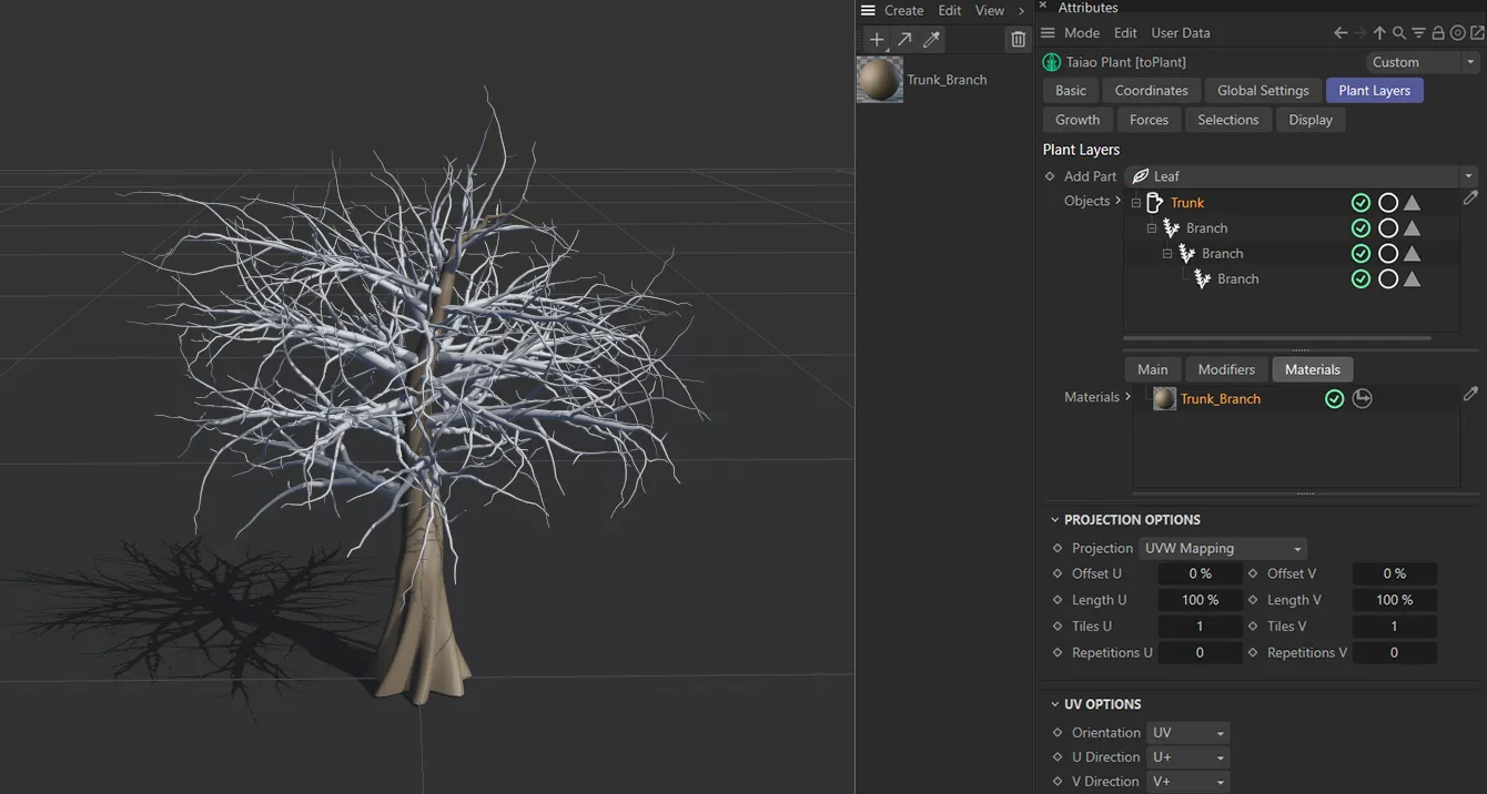
Material added to Trunk layer alone.
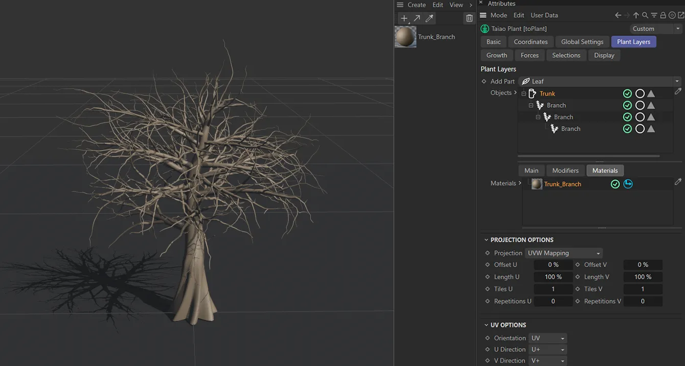
Hierarchy enabled, applying the material to all child Branch layers.
Activating the Hierarchy button (it turns blue when activated), seen enabled in the image below, will attribute the material to relevant child parts.
The single material attributed in the Trunk layer’s Materials link field is now shading all child Branch layers.
Projection Options
Section titled “Projection Options”You can use these options to choose the projection mapping of the texture used.
Offset and Length settings allow you to control the global scale and offsets of the material, while the Tile and Repetition values set how many times the image will tile.
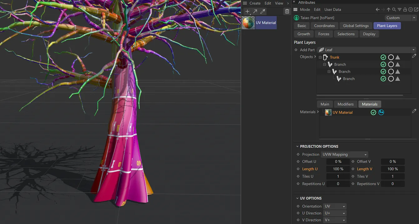
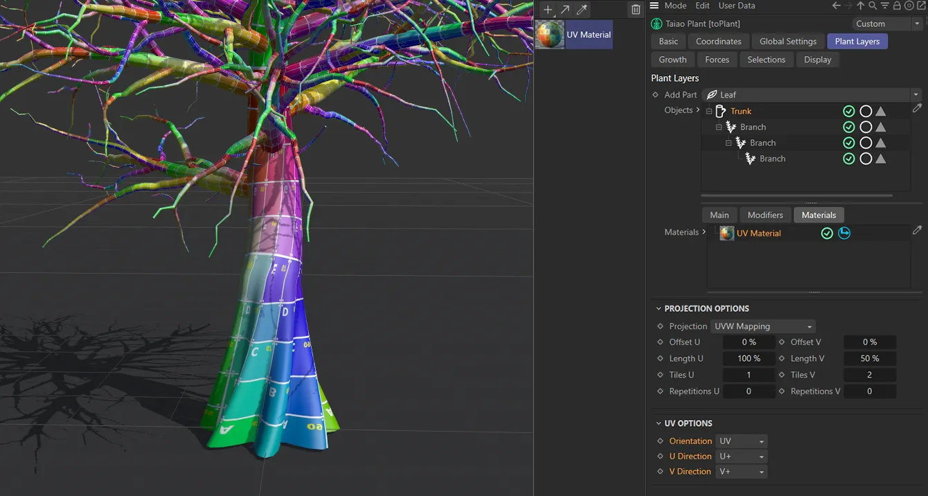
Trunk layer with UV Material applied, with the default Length U and Length V both at 100%.
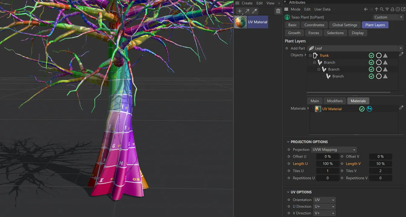
Trunk layer with UV Material applied, but here the Length V is lowered to 50%.
UV Options
Section titled “UV Options”These options will enable you to orientate a correct projection for your scene.
Change the UV directions separately to adjust UV map orientation.
Phong Options
Section titled “Phong Options”These options allow you to adjust the smooth shading between neighboring polygons.
Smooth shading can be applied across all polygons, or it can be restricted using the Angle Limit and Phong Angle settings. **
Angle Limit
Section titled “Angle Limit”When activated, this will use the Phong Angle value to **restrict where smoothing occurs. **
Phong Angle
Section titled “Phong Angle”You can change this to set the angle limit, up until which the neighboring surfaces will be smoothed.
Copyright © 2026 INSYDIUM LTD. All rights reserved.