Growth Point
The growth point will create multiple versions of a given object.
If you add a Growth Point layer to an existing object, you will see that white dots appear inside the green circle.
Changing the hierarchy to make the object a child of that Growth Point layer, will create clones from those white dots (or growth points).
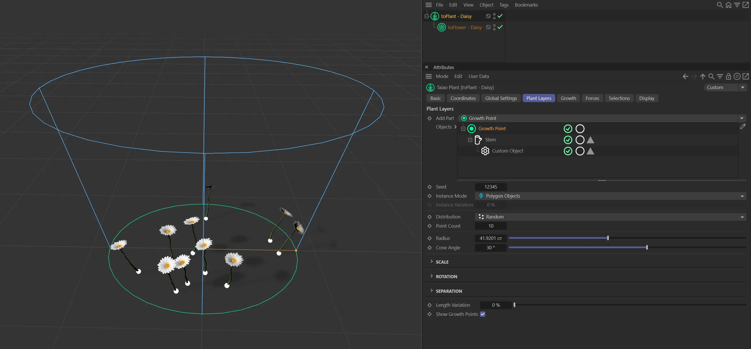
Daisy clones generated as a child of the growth points.
In this image, the Point Count of 10 is creating 10 trees from the Growth Point layer.
Changing the Seed value will give you a different, random, distribution of the points.
Instance Mode
Section titled “Instance Mode”Sets the type of copy to generate.
This can be one of: Polygon Objects, Render Instances or Multi Instances.
Instance Variation
Section titled “Instance Variation”A value from 0 (zero) - 100% that controls what percentage of the copies are different (not clones).
This allows you to take advantage of the speed of render and multi-instances while still maintaining some variation in the clones.
Distribution
Section titled “Distribution”By default, this is set to Random, but there are other modes: Radial, Object Vertices and Object Surface.
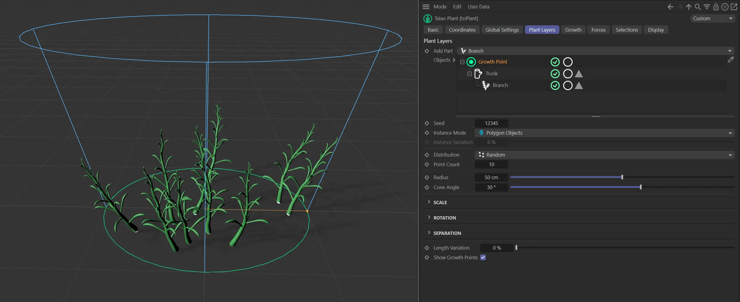
Random mode
Section titled “Random mode”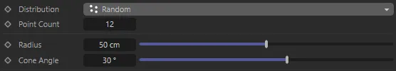
Distribution in Random mode, with parameter options.
In this mode, the growth points are randomly distributed within the green circle, as seen above.
Point Count
Section titled “Point Count”You can increase or decrease the number of points that you are creating.
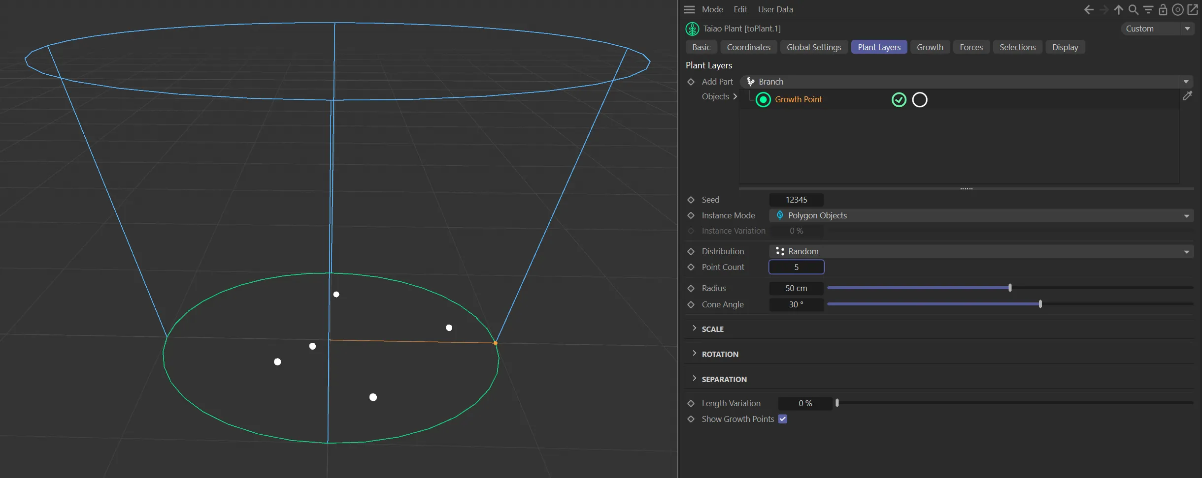
Growth Point layer with a Point Count value of 5.
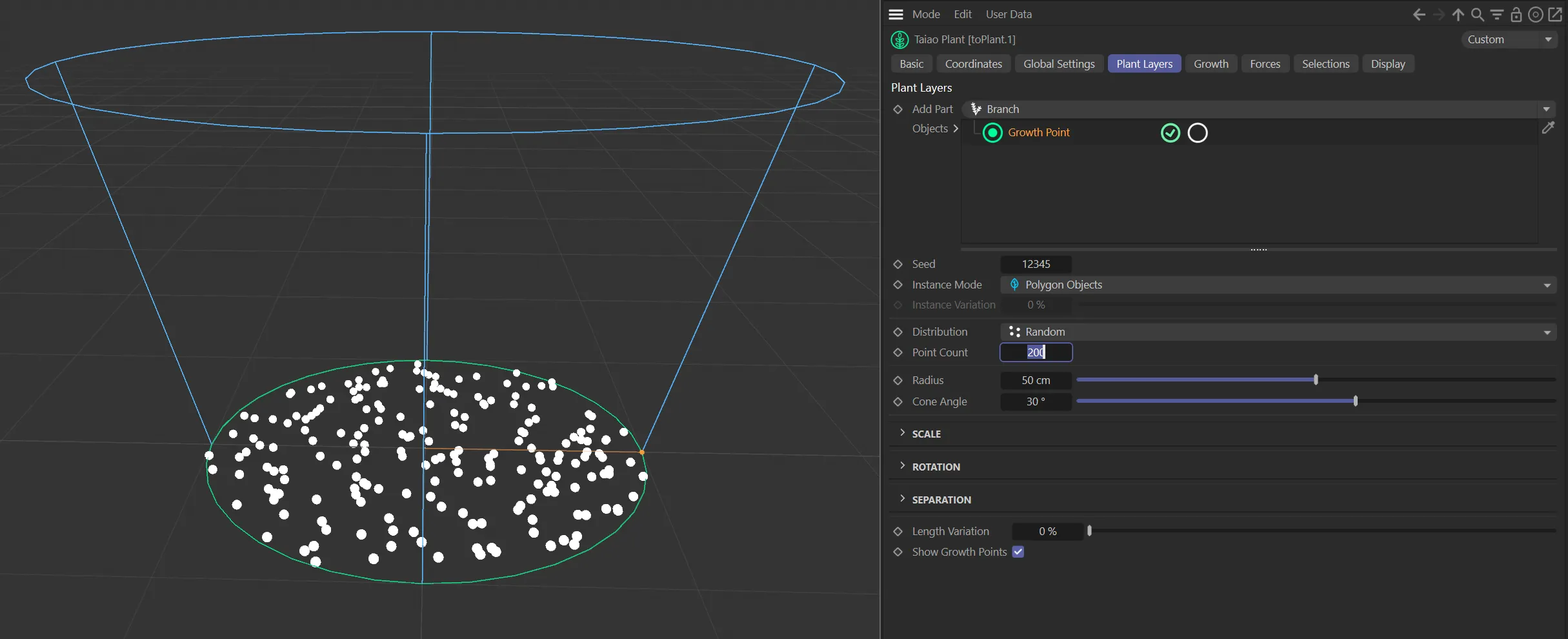
Growth Point layer with a Point Count value of 200.
Radius
Section titled “Radius”The radius of the green circle can be increased or decreased, making the area you are populating larger, or smaller, respectively.
Animation to demonstrate the use of the Radius slider.
Cone Angle
Section titled “Cone Angle”This setting changes the angle of the blue cone, which will, in turn, alter the angle of the clones.
Animation demonstrating the Cone Angle setting changing the angle of the blue cone, in turn, altering the angle of the clones.
Radial mode
Section titled “Radial mode”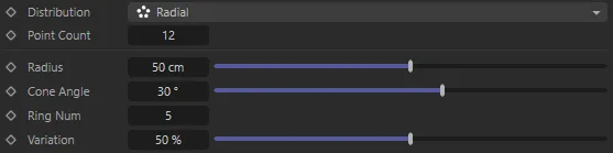
Distribution in Radial mode, with parameter options.
In this mode, the points are distributed in a radial pattern.
At a low Point Count setting, this can be difficult to see, especially if the Ring Number and Variation values are both set higher.
There are two additional parameters available in this mode.
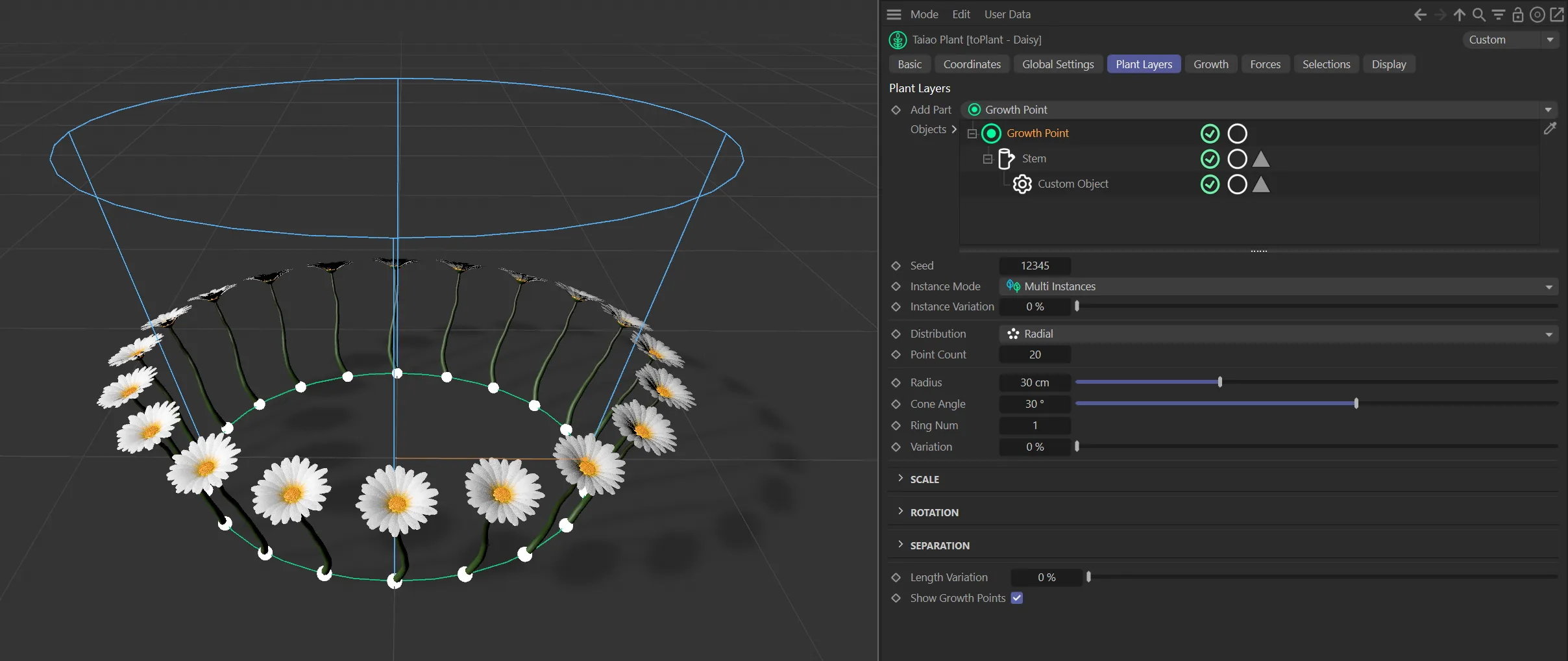
In the Distribution mode of Radial, with a Ring Num value of 1 and a Variation setting of 0 (zero) %. The Point Count of 20 is generating a clear ring pattern.
Ring Num
Section titled “Ring Num”Sets the number of rings that the points are populated in.
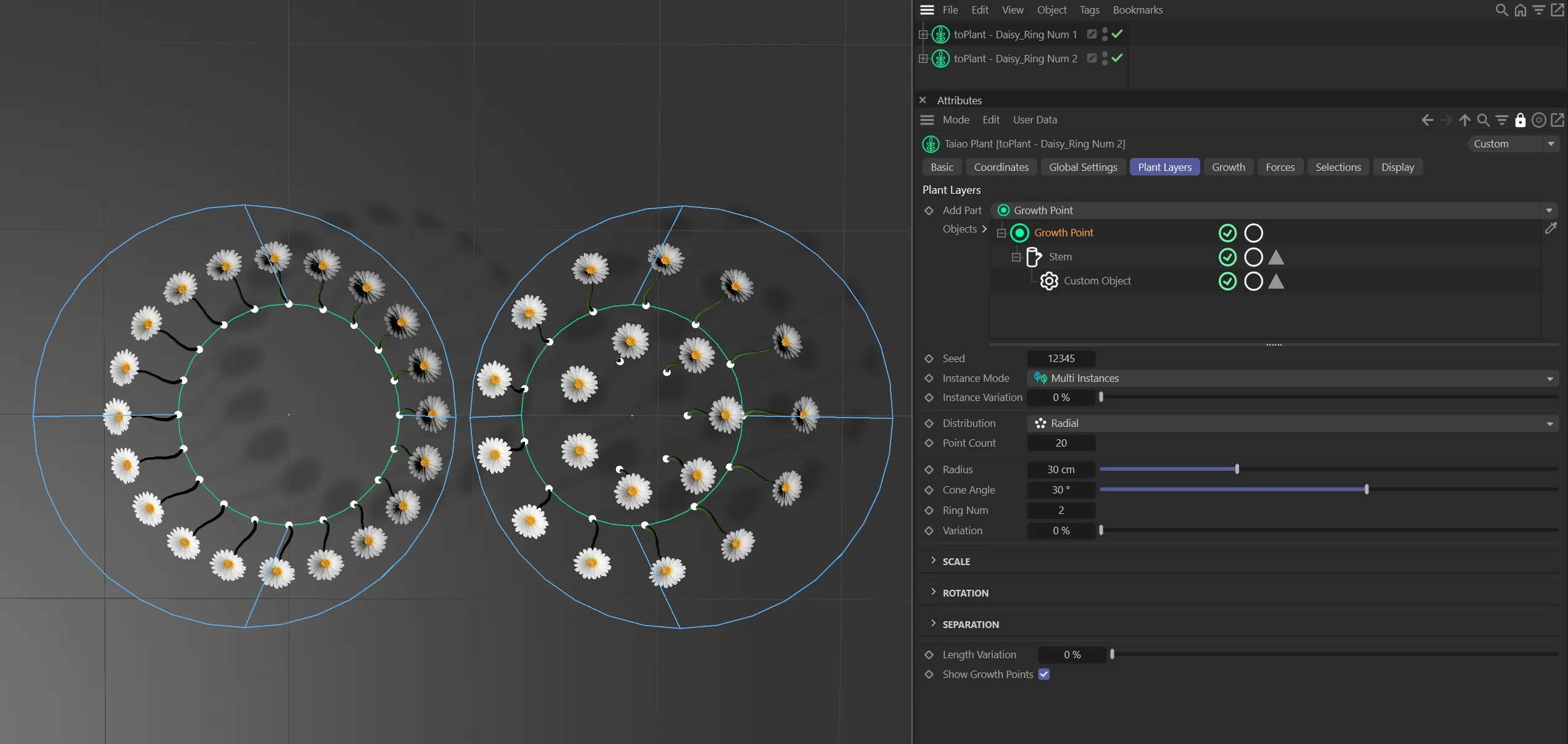
Ring Num of 1 on the left and Ring Num of 2 on the right.
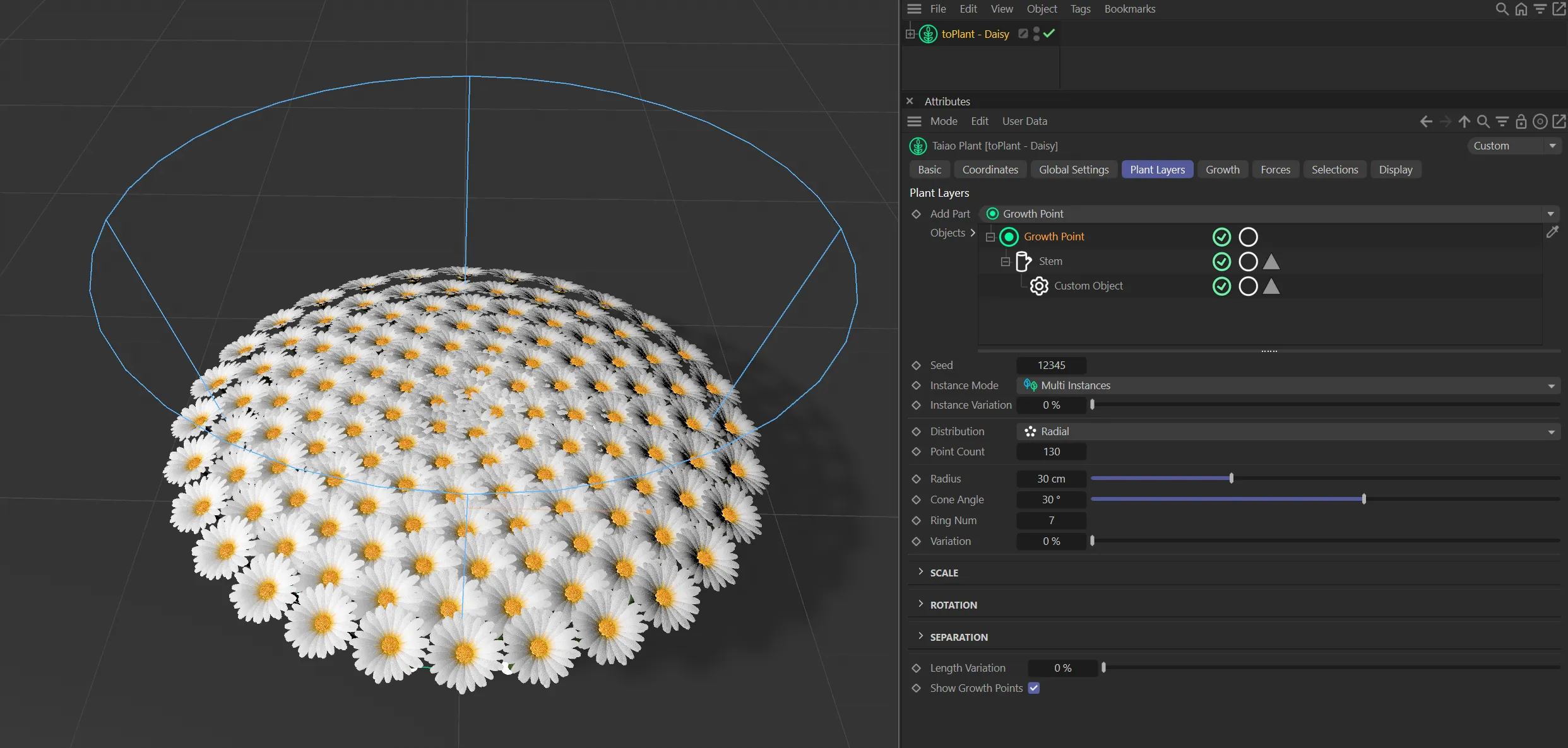
A Point Count of 130 and a Ring Num setting of 7 is generating this image.
Variation
Section titled “Variation”Increasing the percentage on the slider increases the variation.
A high percentage value gives each growth point variation in its position, providing a more natural outcome.
Animation to demonstrate the effect of the Variation slider.
Object Vertices mode
Section titled “Object Vertices mode”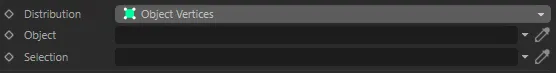
Distribution in Object Vertices mode, with parameter options.
In this mode, you can use scene geometry to clone your plant.
Object
Section titled “Object”Drag your scene geometry into this field, in order to use it as a base for growth points.
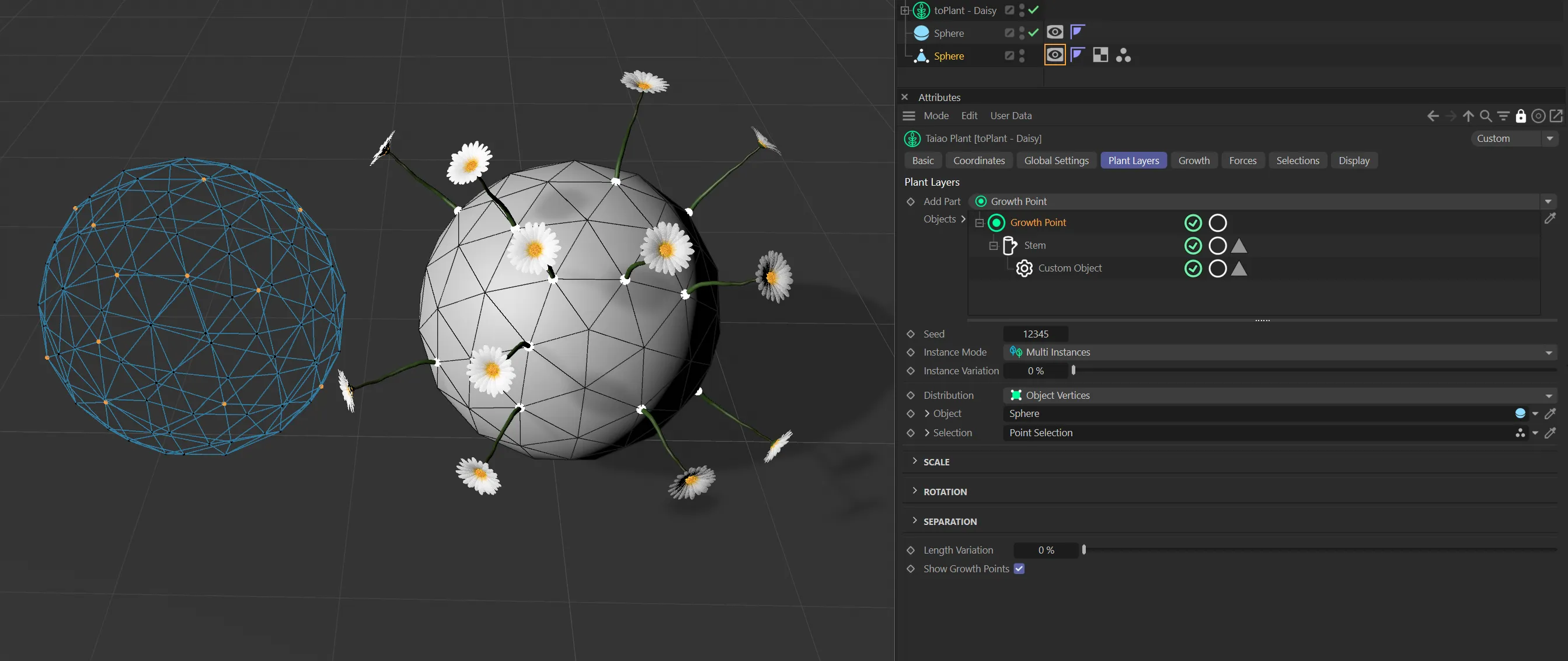
By changing the Distribution mode to Object Vertices and importing the Sphere into the Object link field (below), you will see that it has been used as the base geometry for the Growth Point layer.
A growth point has been established on each vertex of the Sphere (you will need to change the Display settings for the Sphere to Shading with Lines, to view this).
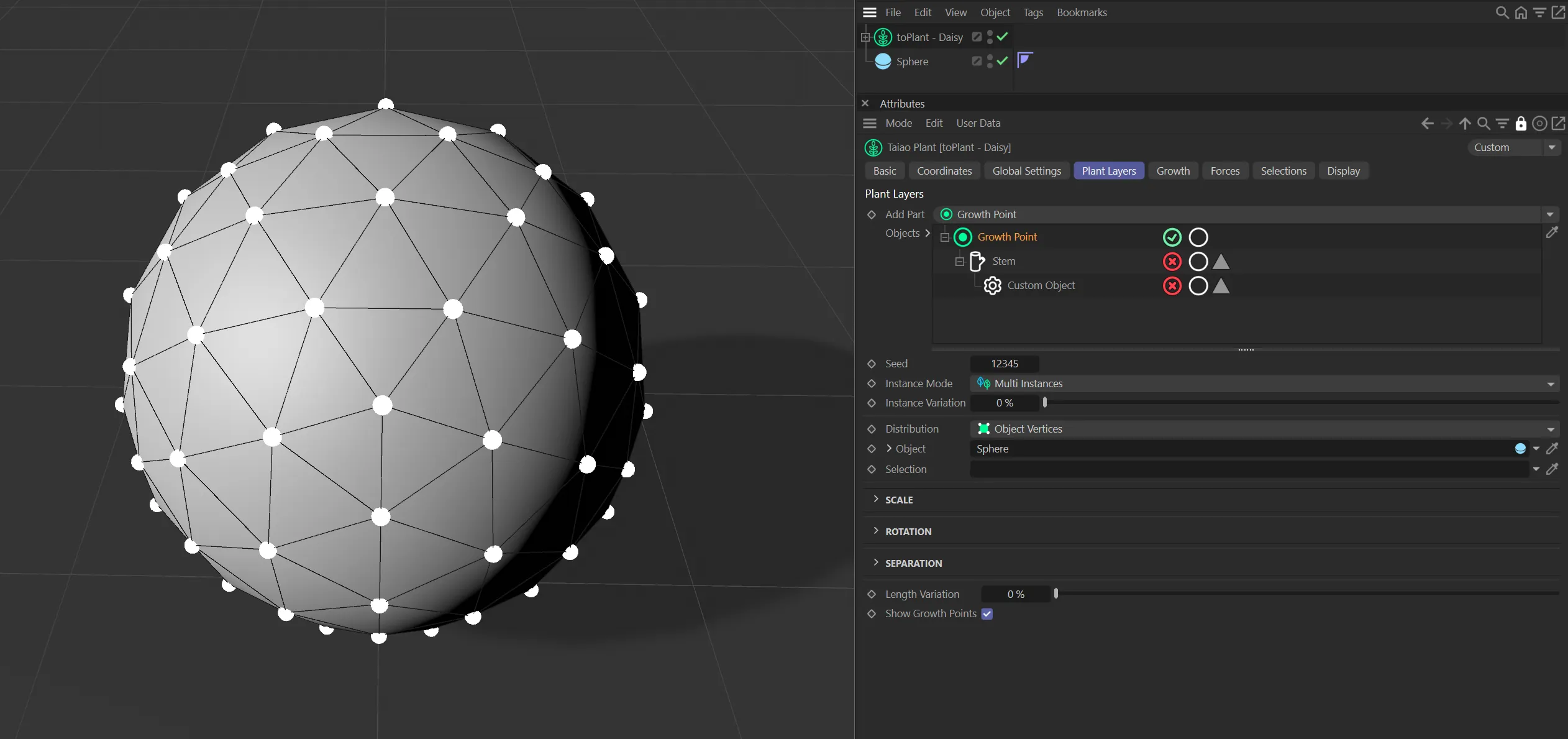
Sphere being used as base geometry for the Growth Point layer, with a growth point on each vertex.
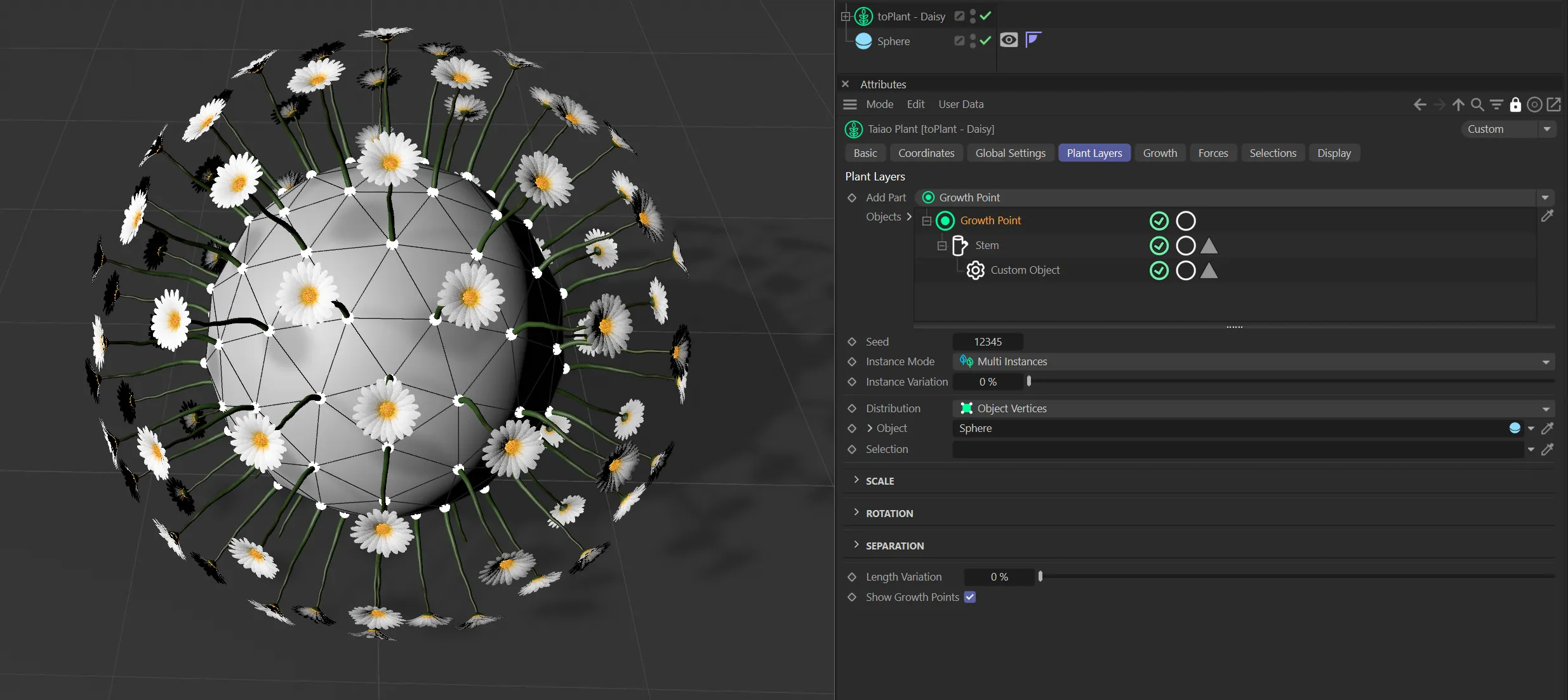
With plants activated.
Selection
Section titled “Selection”You can import selection tags into this field, to dictate where on your geometry growth points are generated.
You can also use vertex maps to do the same thing.
The selection tag has been dragged and dropped into the Selection link field.
Here you can see the active point selection in the Sphere on the left and the results on the right.
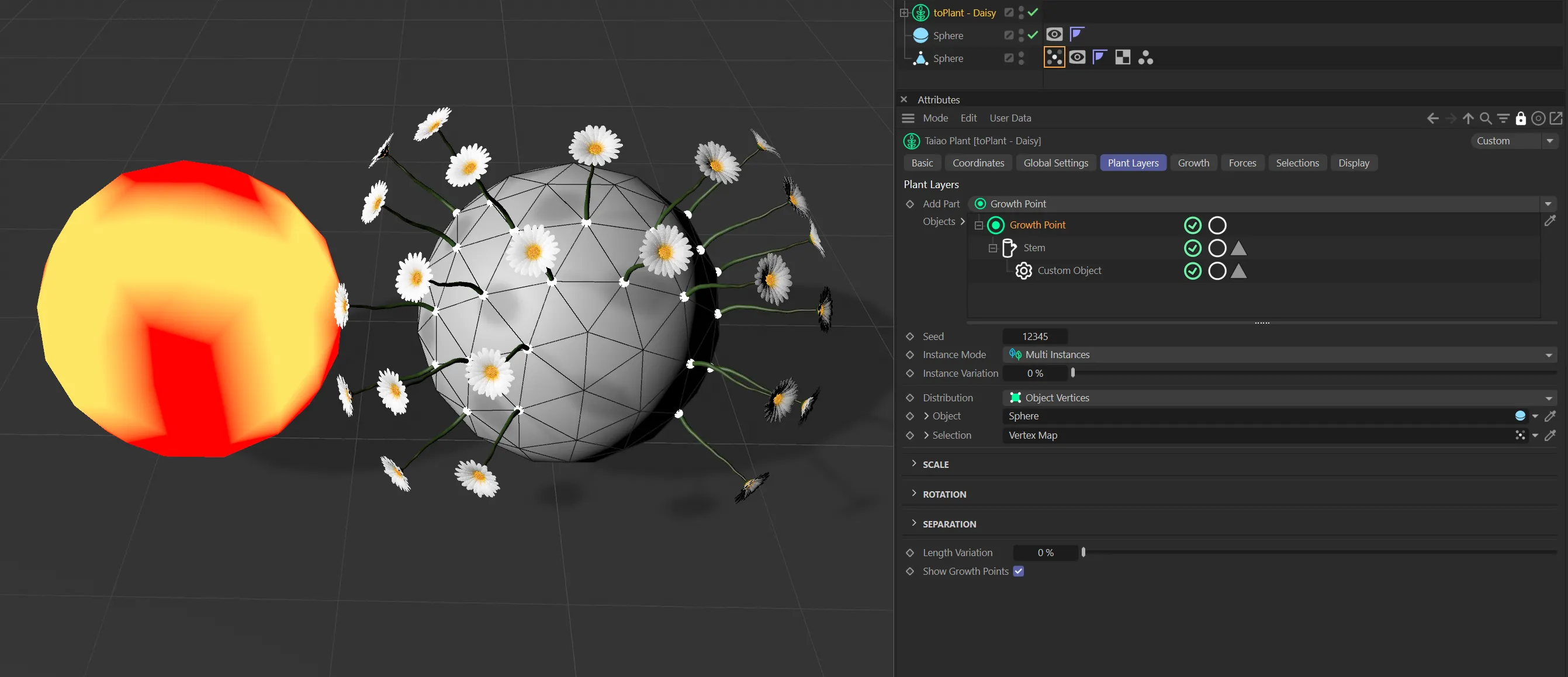
The results here are driven by the vertex map weighting, with the flower disabled on the left and enabled on the right.
Object Surface mode
Section titled “Object Surface mode”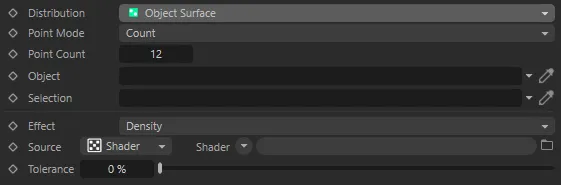
Distribution in Object Surface mode, with parameter options.
Use this mode for a random distribution of points over an object’s surface.
The parameter, Point Mode becomes available in this mode.
Point Mode
Section titled “Point Mode”There are two settings: Count and Density.
Count mode
Section titled “Count mode”This gives you a specific number of points, which you can alter in the Point Count parameter.
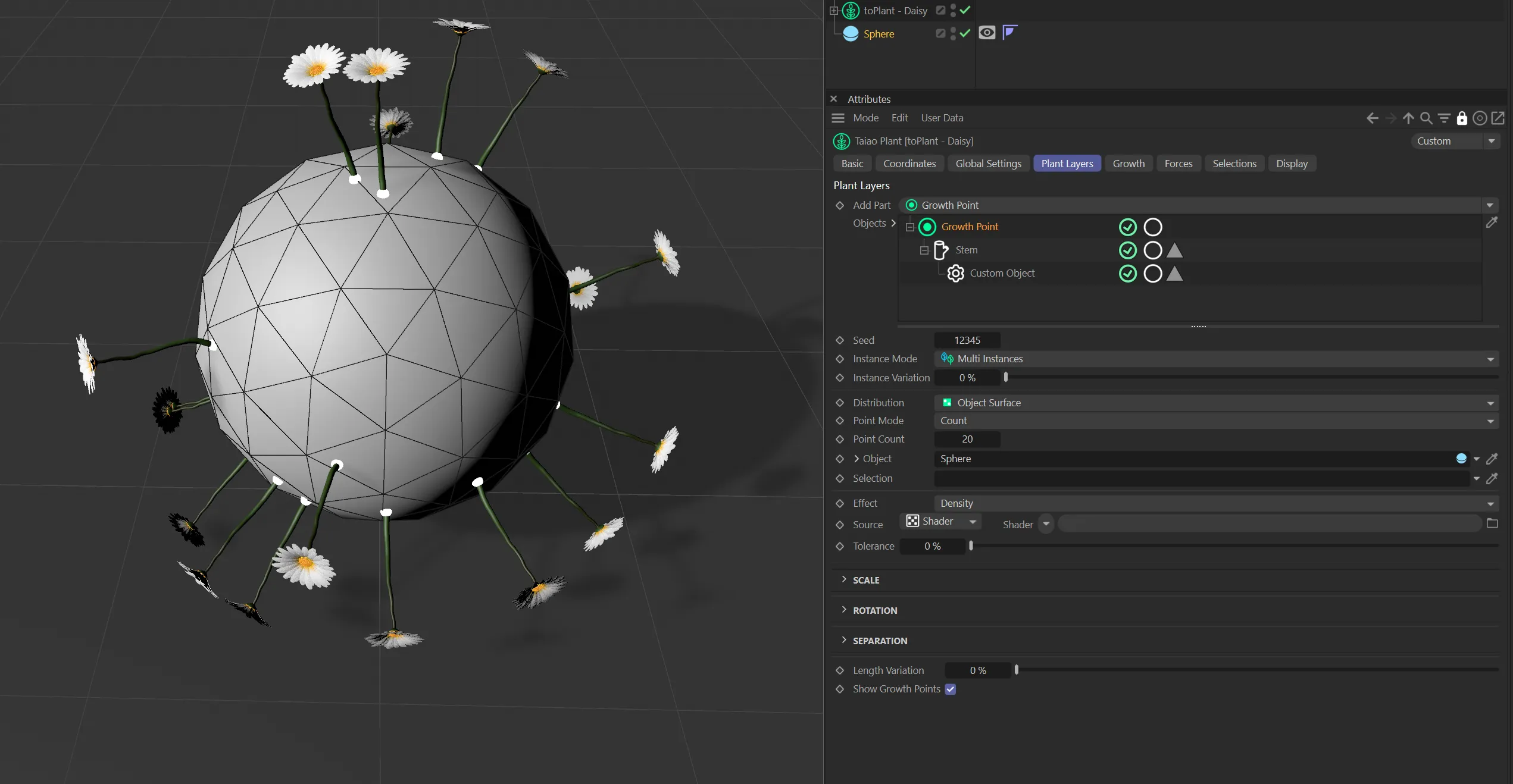
Point Mode in Count setting with a Point Count value of 20.
Point Count
Section titled “Point Count”The number of growth points on the surface of the object.
This can be altered with the slider, or by manually inputting a number.
Density mode
Section titled “Density mode”Using the Density mode gives you the option to decide on the density of growth points on the surface of your object.
Point Density
Section titled “Point Density”The Point Density slider works on a percentage scale, the higher the percentage, the greater the density of points.
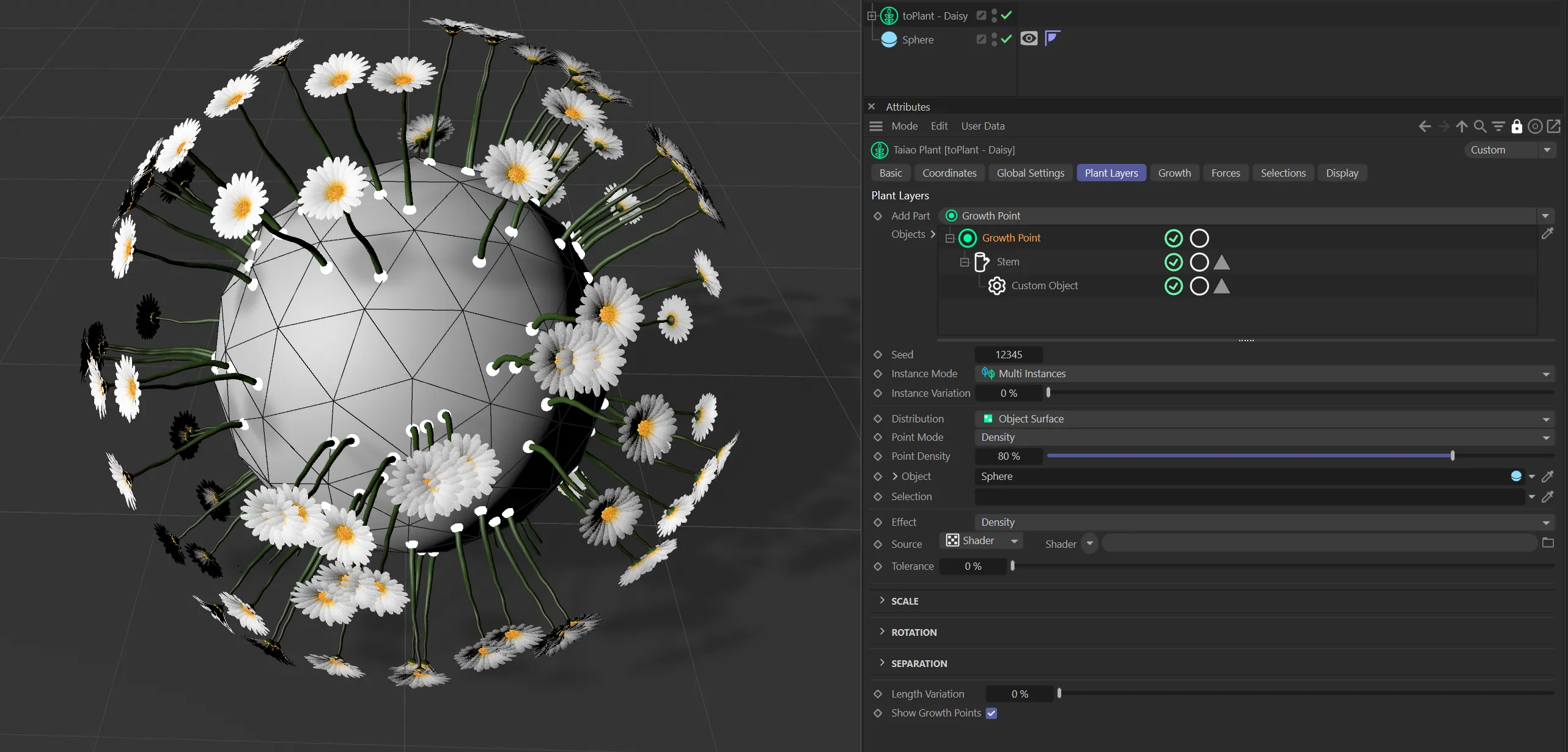
Point Mode in Density setting with a Pont Density value of 80%.
Object
Section titled “Object”Drag your scene geometry into this field, in order to use it as a base for growth points (as explained in Object Vertices mode, above).
Selection
Section titled “Selection”As with the Object Vertices mode, you can drag a vertex map or a selection tag into this field, to specify where you would like the growth points to be placed.
Effect
Section titled “Effect”Determines how the linked texture or shader is applied to the growth point generation.
Using Density will have higher density for brighter parts of the texture; using Scale will scale the size of the clone based on the brightness of the texture at that point.
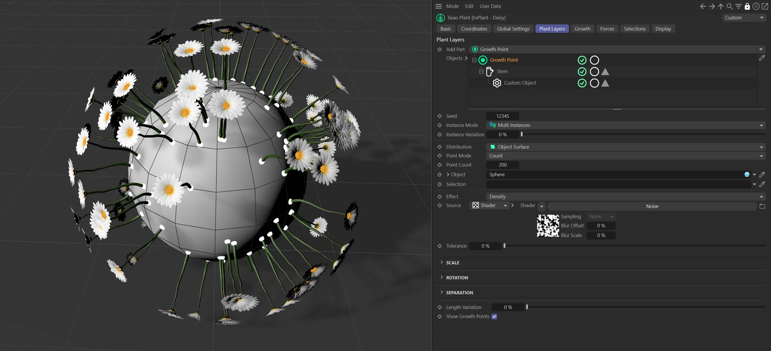
Effect set to Density using a Cinema4D noise
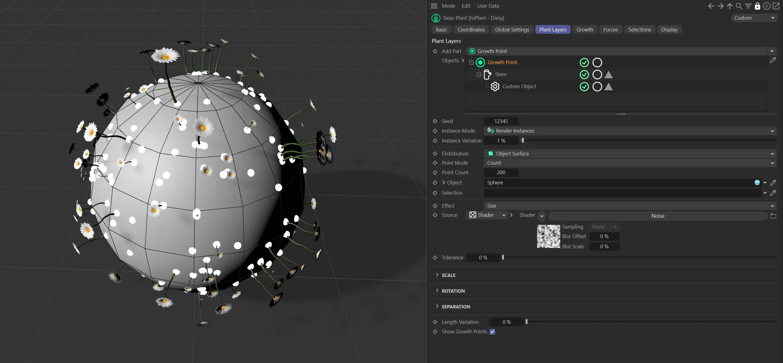
Effect set to Size using a Cinema4D noise
Source
Section titled “Source”Whether to use a texture or shader.
Tolerance
Section titled “Tolerance”The Tolerance setting controls the amount of growth points generated, by using the slider.
A high tolerance value will utilize only the brightest areas, generating a low count.
Any points on the texture darker than the Tolerance level will be treated as zero.
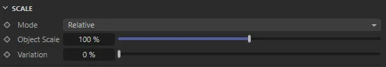
Scale parameter options.
Sets the mode of scaling, either Relative or Absolute.
Relative scaling uses a single percentage to scale the objects, whereas Absolute scaling gives you control over the scaling in the x, y and z directions.
Object Scale
Section titled “Object Scale”The percentage scale factor that will be applied to the objects.
This animation shows a demonstration of the Object Scale slider.
Variation
Section titled “Variation”Adds some random variation on the scale across the objects.
The maximum/minimum scale for this variation is the scale percentage plus/minus the variation value.
With the Object Scale set at 100%, this animation demonstrates the effect of the Variation slider.
Rotation
Section titled “Rotation”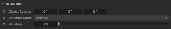
Rotation parameter options.
Object Rotation
Section titled “Object Rotation”Gives a HPB (Heading, Pitch or Bank) rotation to apply to all objects.
In this animation, the values in the Heading, Pitch and Bank are all demonstrated, before the Variation slider is increased up to 100% variation on the Object Rotations set.
Variation Mode
Section titled “Variation Mode”Sets the type of variation to apply, either Relative or Absolute.
Relative variation will vary the rotation in each axis by plus/minus the percentage given of the applied rotation.
Absolute variation will vary the rotation by plus/minus an angle given for each axis.
Variation
Section titled “Variation”Either a percentage value for Relative variation or the HPB angles for the variation in Absolute mode.
Separation
Section titled “Separation”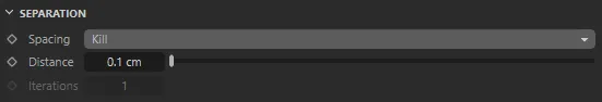
Separation parameter options.
In this scene, with Spacing set to Push, the effect of the Distance slider is shown.
Spacing
Section titled “Spacing”The spacing mode can be set as either None, Kill or Push.
None will have no effect.
Kill will remove points so that the minimum distance between any two points is greater than the specified Distance parameter.
Push will iteratively push any points in the Distance range apart.
Distance
Section titled “Distance”The distance parameter used by the Kill and Push separation methods.
Iterations
Section titled “Iterations”The number of iterations to run the push apart procedure.
Only applicable to the Push mode.
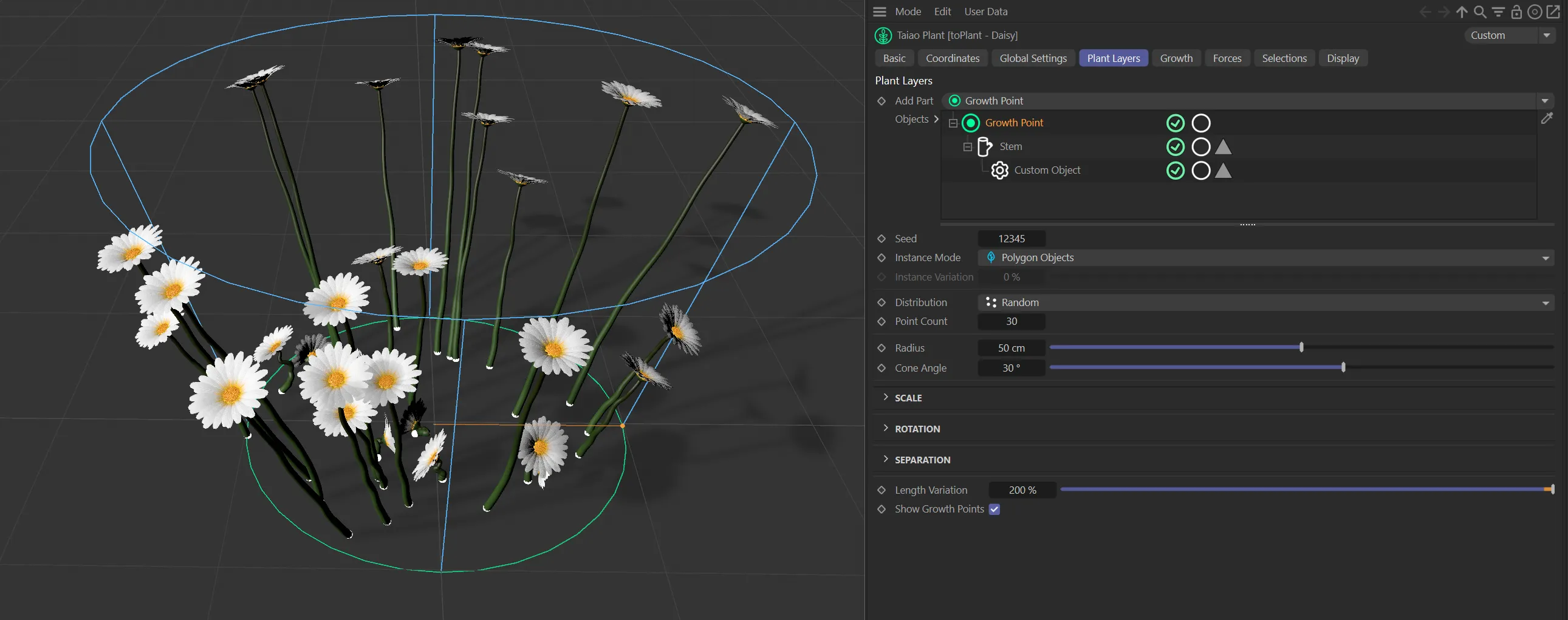
Length Variation
Section titled “Length Variation”This option adds variety to the length of the plants that you have cloned.
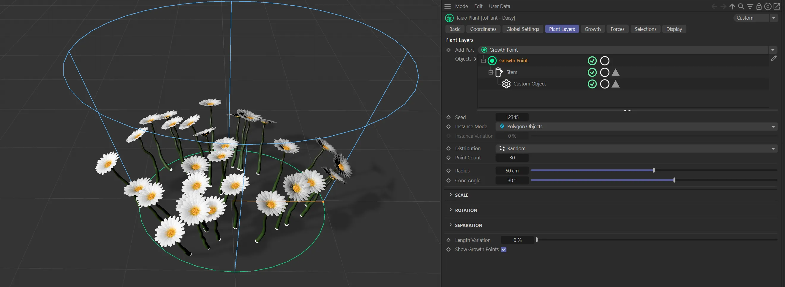
Show Growth Points
Section titled “Show Growth Points”This is enabled, by default.
Simply clicking this, to disable it, will hide the growth points (and cone) from the scene.
Copyright © 2026 INSYDIUM LTD. All rights reserved.