Branch
Adding a branch, in the Plant Layers menu, can be done by highlighting Trunk, then selecting the Branch layer from the Add Part drop-down menu.
By highlighting the Branch layer, you will access the individual settings, with the four tabs: Main, Modifiers, Distribution and Materials.
Animation to show the addition of the Branch layer from the Add Part menu.
Main tab
Section titled “Main tab”Branch Count
Section titled “Branch Count”Here you can increase, or decrease, the number of branches on your trunk.
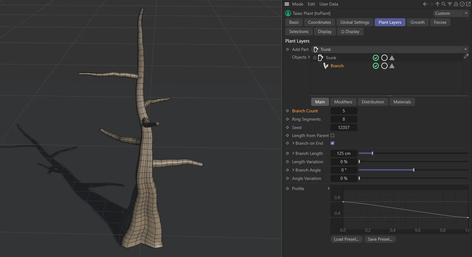
Branch Count value of 5.
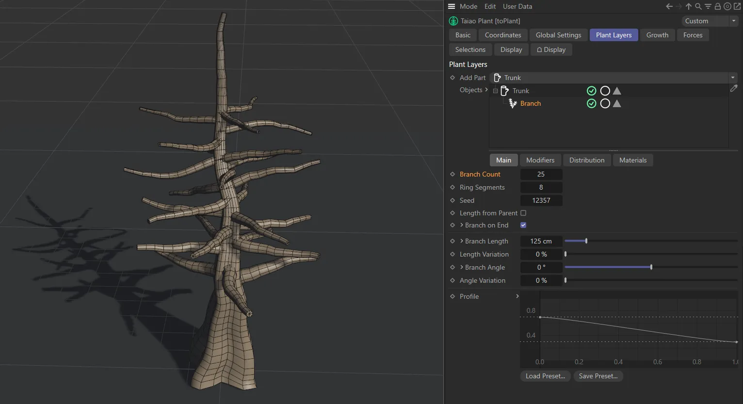
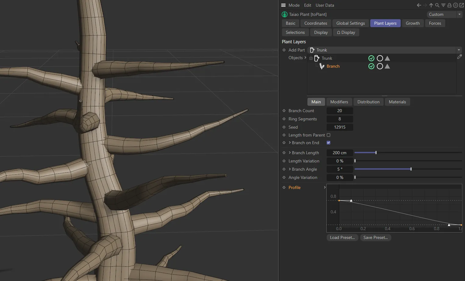
The Branch Count in this image is 25.
Length Segments
Section titled “Length Segments”This option is only visible if the Use Resolution box is unticked in the Global Settings tab.
It controls the number of length segments you have in your Branch layer - the higher the number, the better the resolution will be.
If Use Resolution is ticked in the Global Settings tab, then there will be a length segment every 10cm (by default), unless the Segment Resolution value is changed.
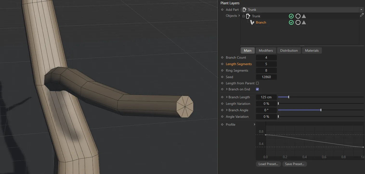
Branch with a Length Segments setting of 5, giving 5 length segments.
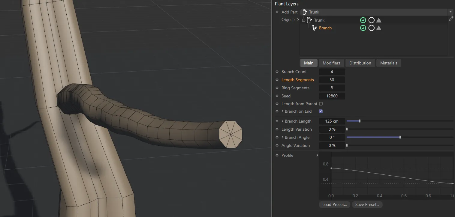
Branch with an increased Length Segments setting of 30.
Ring Segments
Section titled “Ring Segments”Controls the number of segments in each ring.
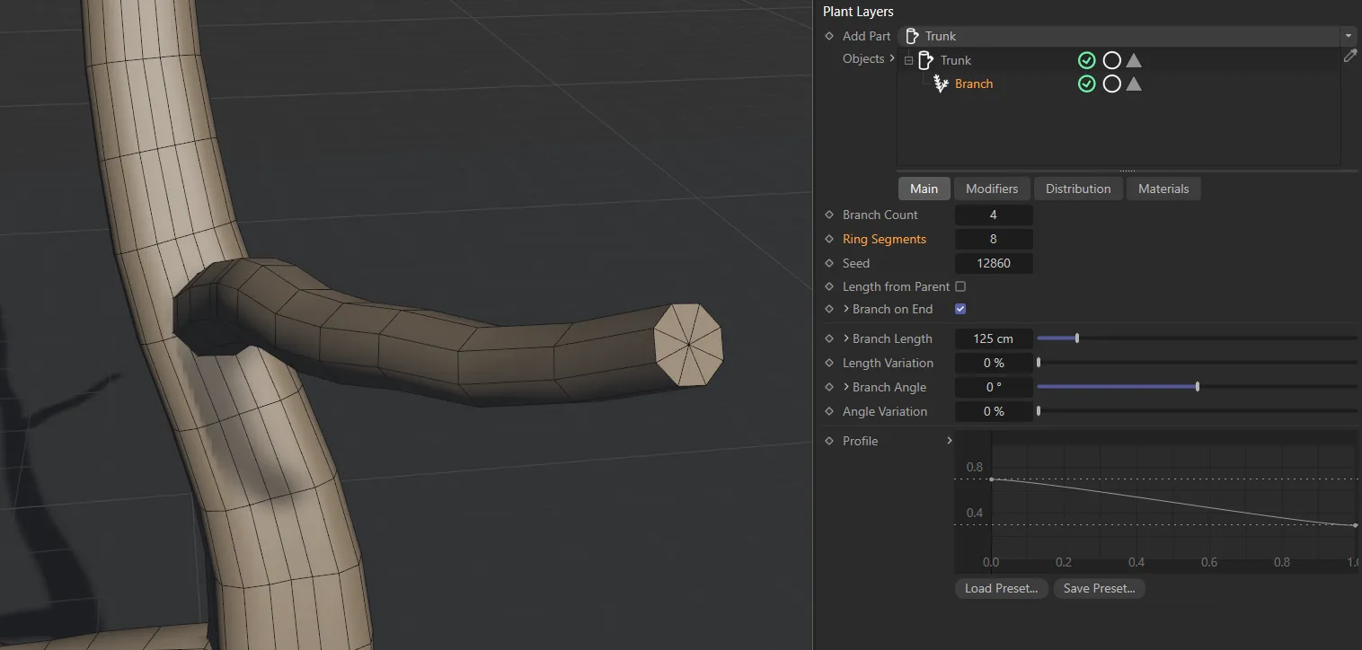
Branch layer with Ring Segments set at 8.
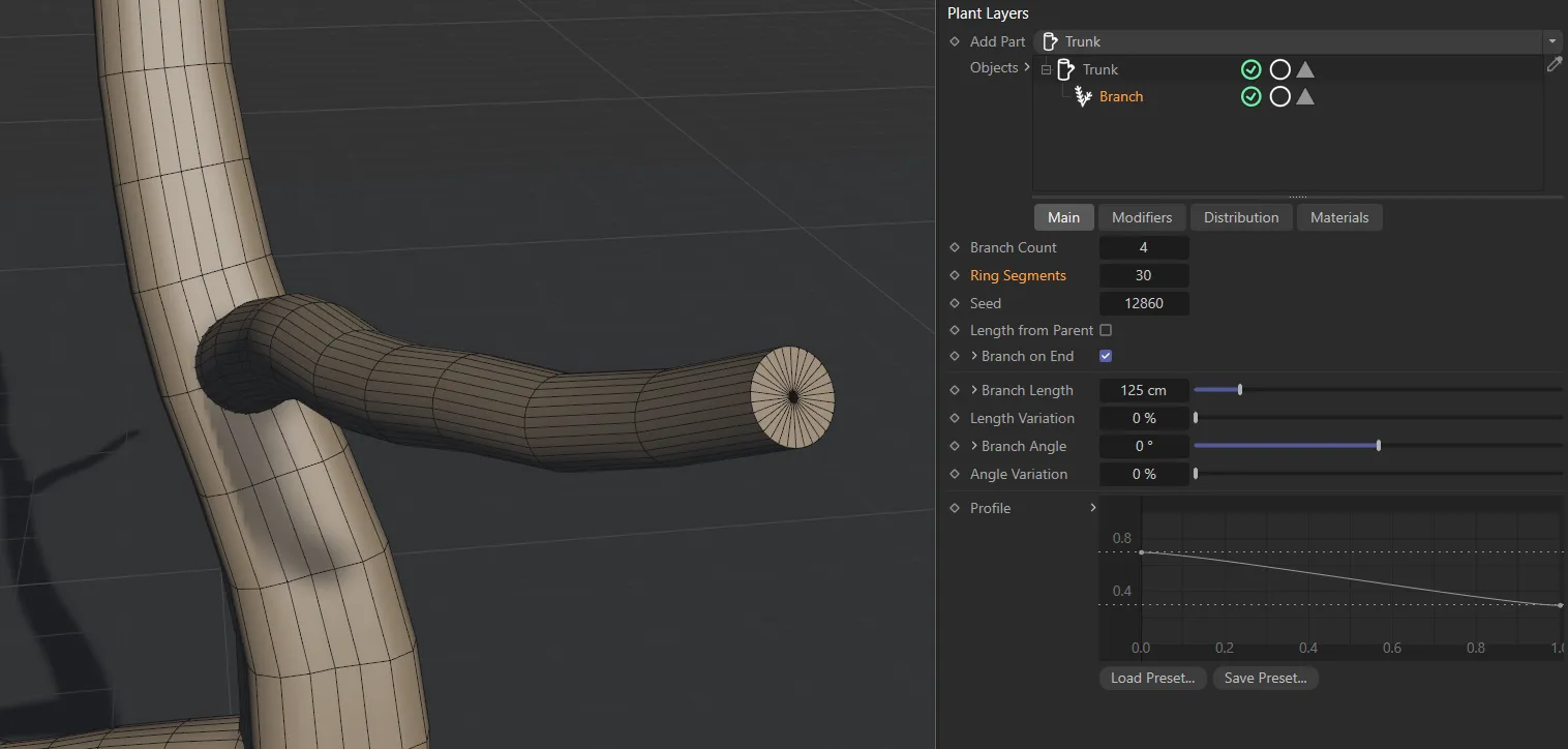
Branch layer with Ring Segments set at 30.
This will slightly change the distribution of your branches, to give a different looks.
Length from Parent
Section titled “Length from Parent”Activating this parameter will change the branch length to a percentage value of the parent layer’s length.
This percentage will then be controlled by the Branch Length slider setting.
Branch on End
Section titled “Branch on End”Switched on, by default, this adds a branch on the end of the parent layer.
Clicking on the drop-down arrow, next to this parameter, will open up a Length option.
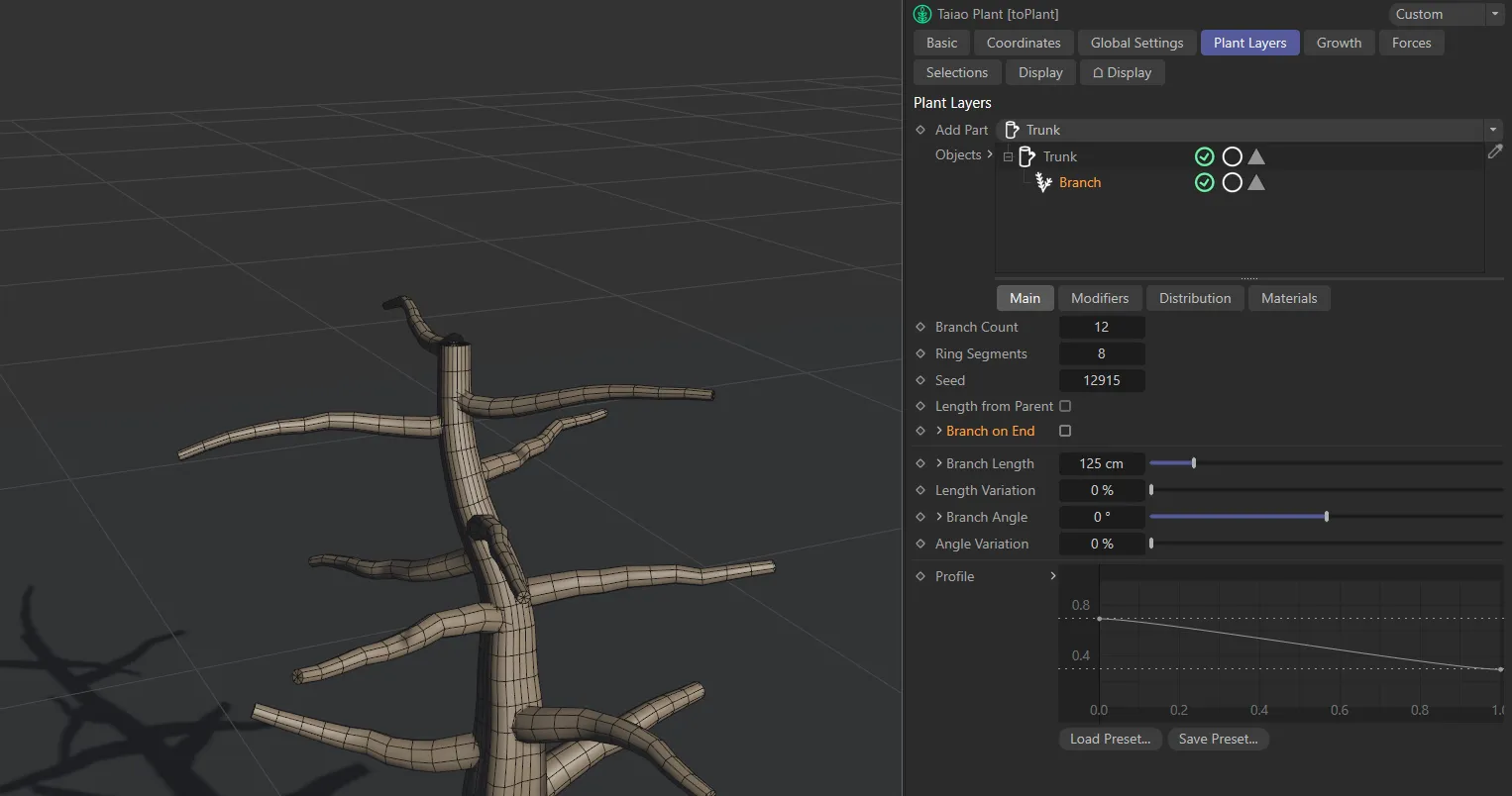
Branch on End switched off.
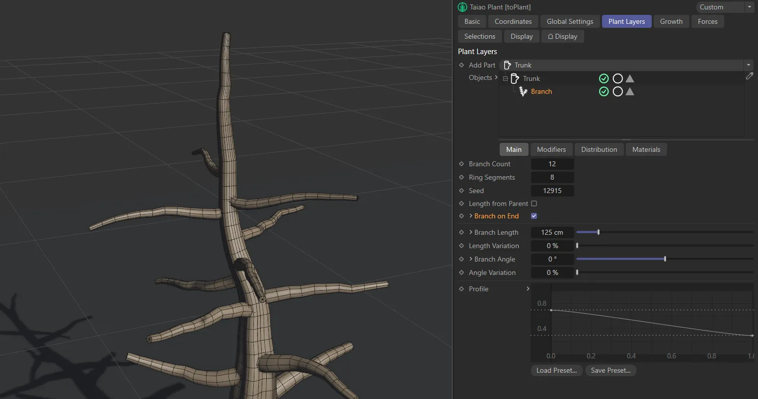
Branch on End switched on.
Length
Section titled “Length”This controls the length of the branch on the end of the parent layer.
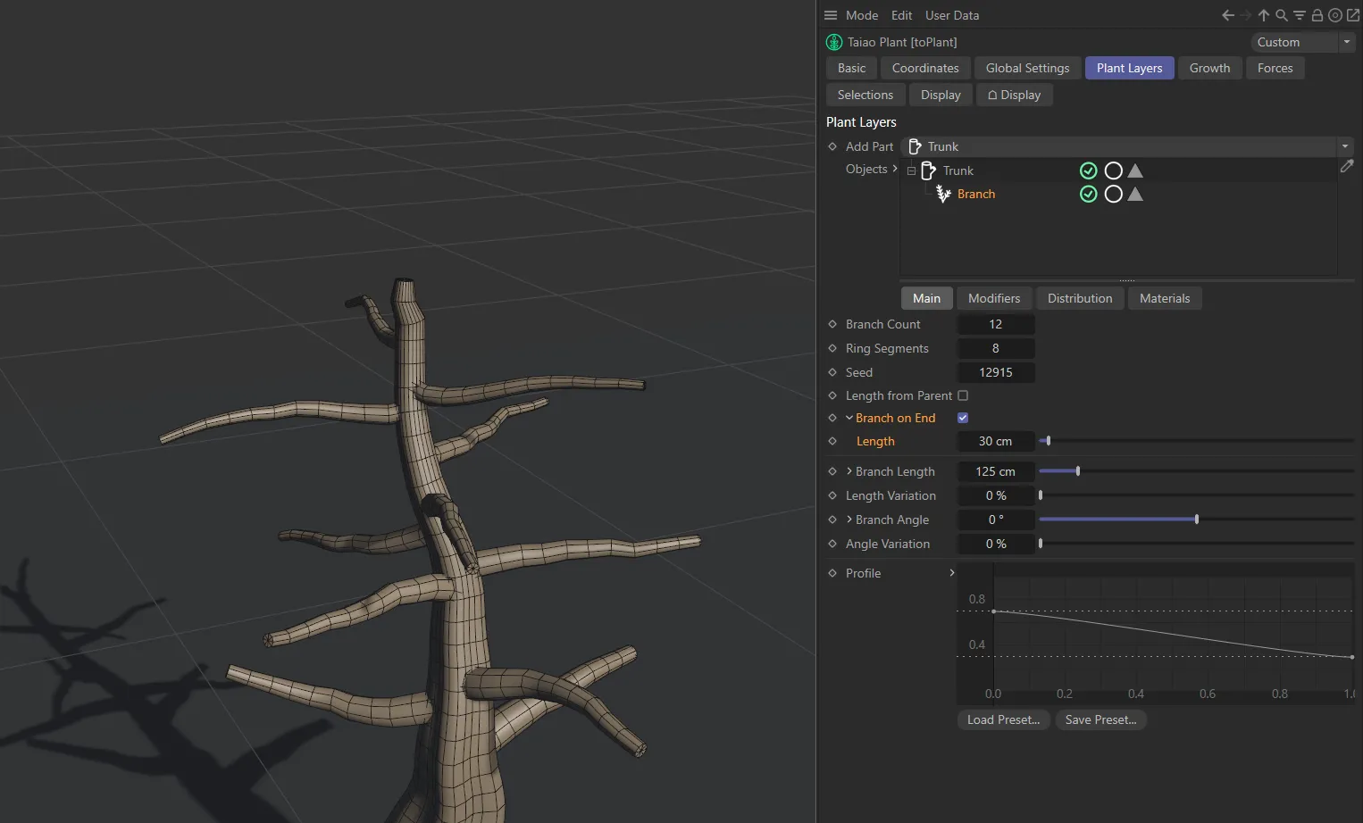
Branch on End enabled, with the Length option unfolded and set at a value of 30cm.
Branch Radius
Section titled “Branch Radius”This option is only visible if you have Use Parent Radius unchecked in the Global Settings tab.
It gives you the ability to change the radius from its default setting of 1cm, to make it a larger radius than is possible with the Use Parent Radius switched on.
The Profile of the branch can then be set using the spline curve, described in the option below.
Branch Length
Section titled “Branch Length”Can be increased, or decreased, to set the length of your branches.
In addition, clicking on the drop-down arrow will open a Length Along Branch display.
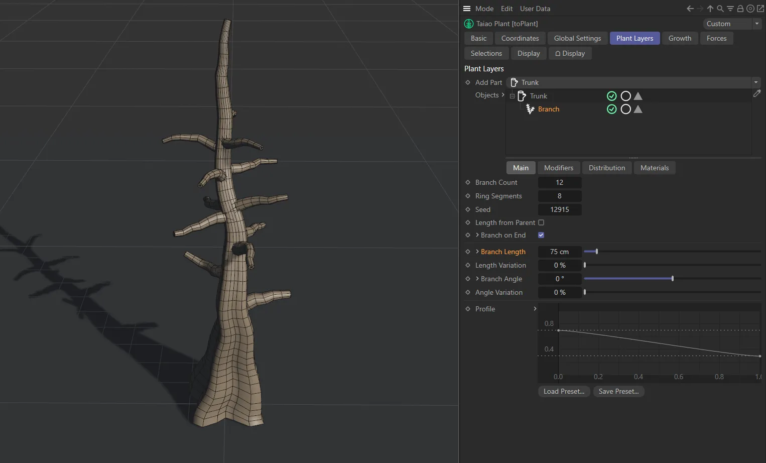
Branch Length set to 75cm.
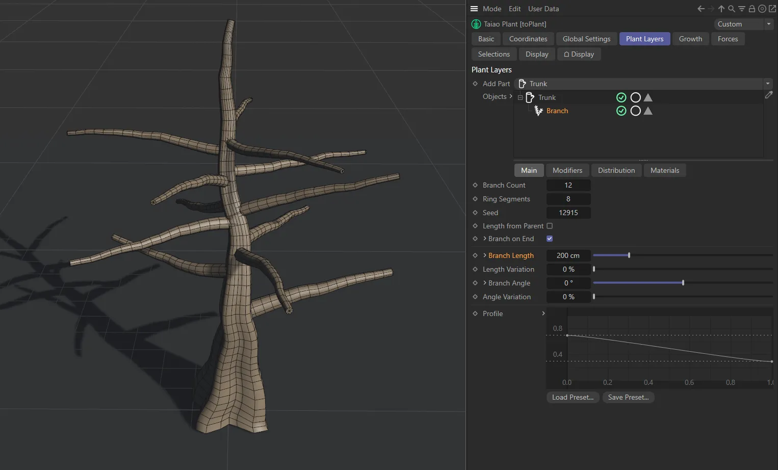
Branch Length at 200cm.
Length Along Branch
Section titled “Length Along Branch”Manipulating this spline will allow you to design your own profile for the branches, with the X-axis representing the length of the trunk and the Y-axis being the length of the branch.
By pulling down the spline at the right end (as below), you will have longer branches at the bottom of the trunk and shorter ones higher up.
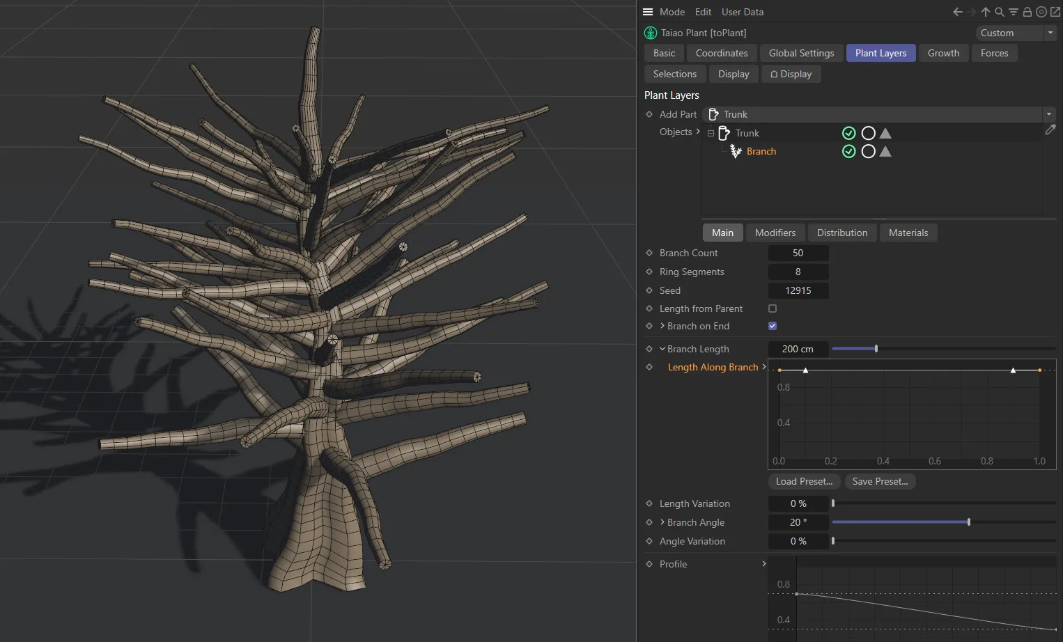
In this image, with the spline curve at maximum, the branches are all at the Branch Length setting of 210.1 cm.
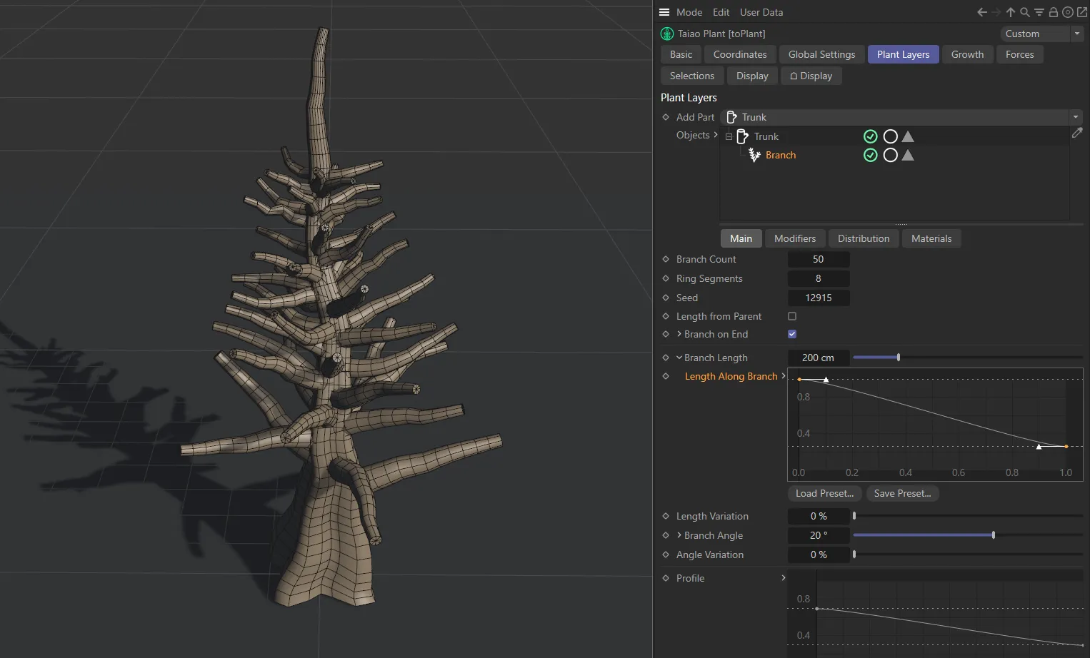
Here the Length Along Branch has a linear falloff on the X-axis from the maximum, 210.1cm Branch Length setting, at the bottom of the trunk.
Length Variation
Section titled “Length Variation”This percentage slider adds variation to the length of the branches.
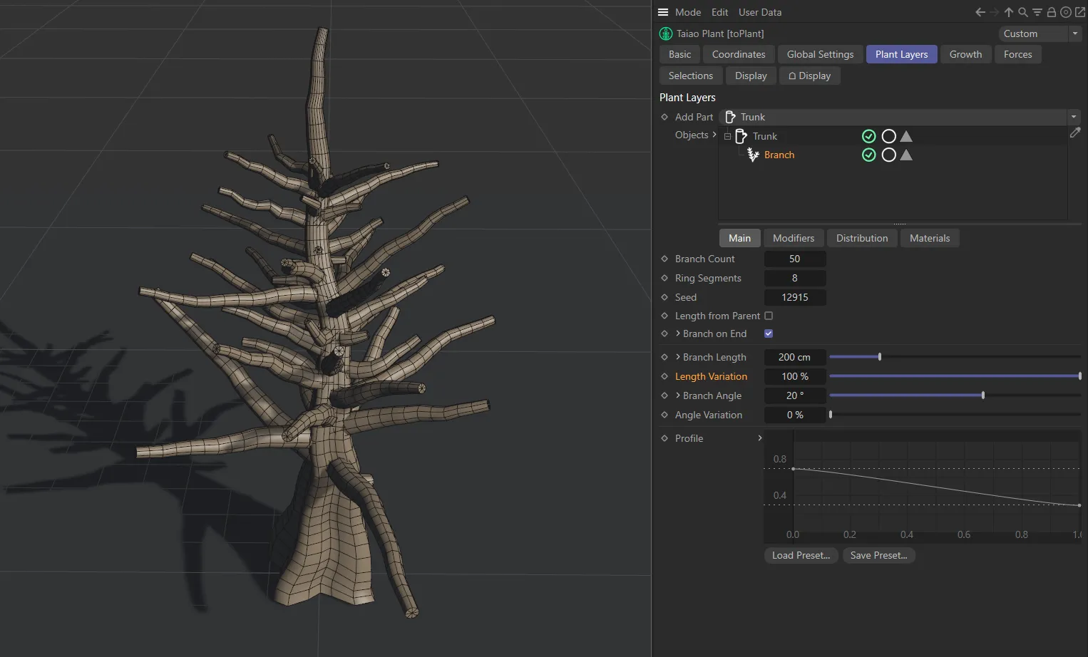
In this image, the Length Variation is set to 100%, making every branch a different length, up to the 200cm set in Branch Length.
Branch Angle
Section titled “Branch Angle”By default, your branches will be set at 0 (zero) degrees, which is at 90 degrees to the Trunk layer.
You can adjust this slider to raise or lower this angle.
Clicking the drop-down arrow will reveal a further option: Bias.
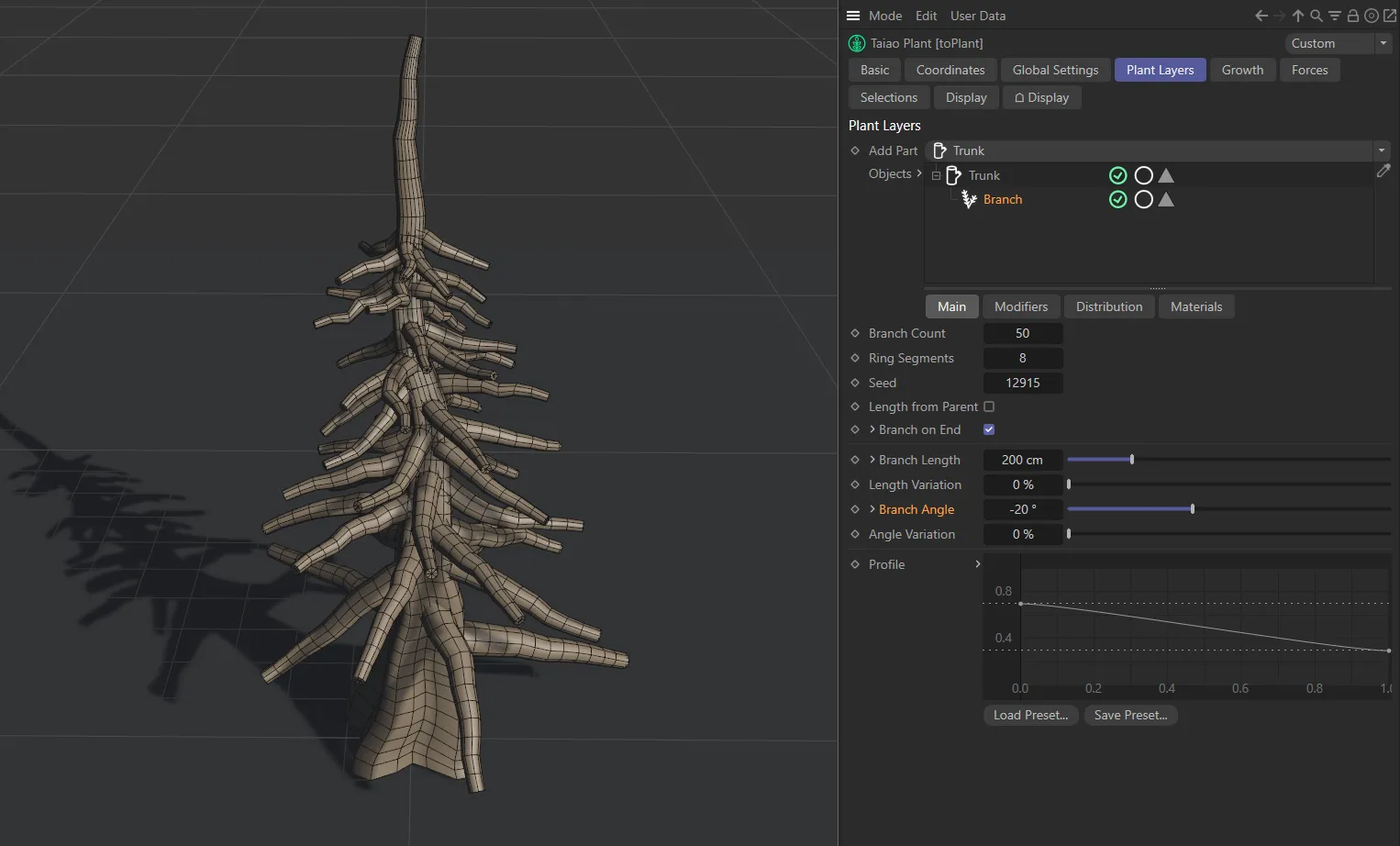
Here, the Branch Angle is set at (negative) -20 degrees.
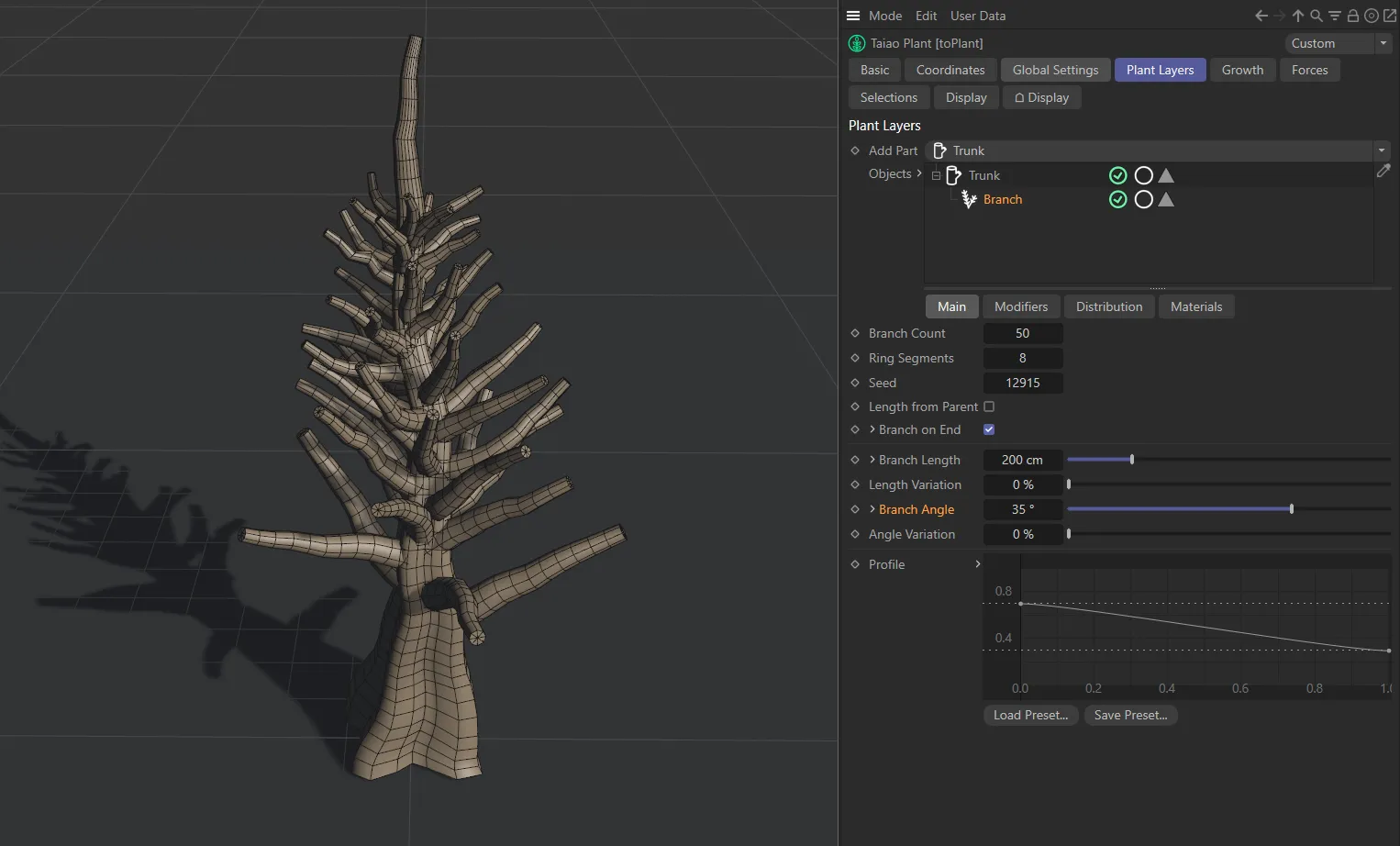
Branch Angle set at 35 degrees.
Set, by default, so that the branches, all the way up the trunk, are at the same angle.
As above, the X-axis represents the length of the trunk, but here the Y-axis is the angle size, so it is possible to set a bespoke change of angles up the length of the trunk.
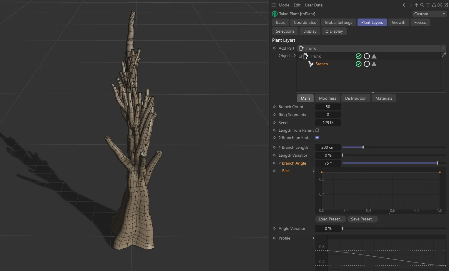
In this image, with the default Bias graph, all branches retain the same angle along the trunk length.
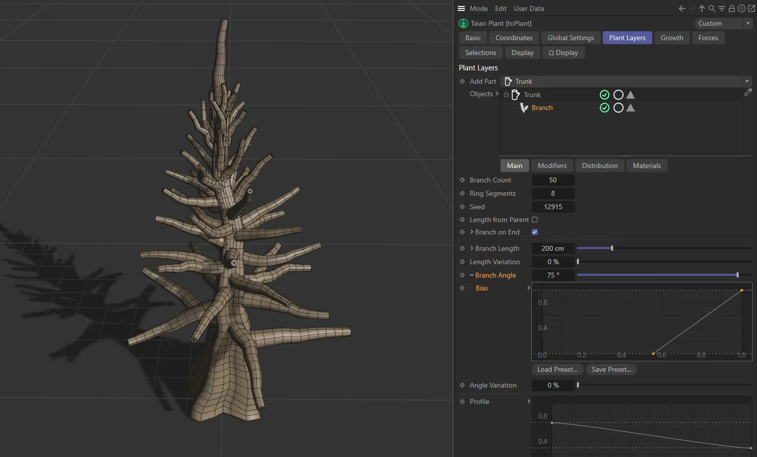
In the image above, you can see a linear increase from 0 (zero) degrees at the lowest branch, up to the full Branch Angle amount of 75 degrees at the top of the tree.
Angle Variation
Section titled “Angle Variation”Use this slider to achieve a more natural, realistic look, applying a variation to the angles of the different branches.
With the Angle Variation set to 100%, each branch will be designated an angle value between 0 (zero) and 90 degrees.
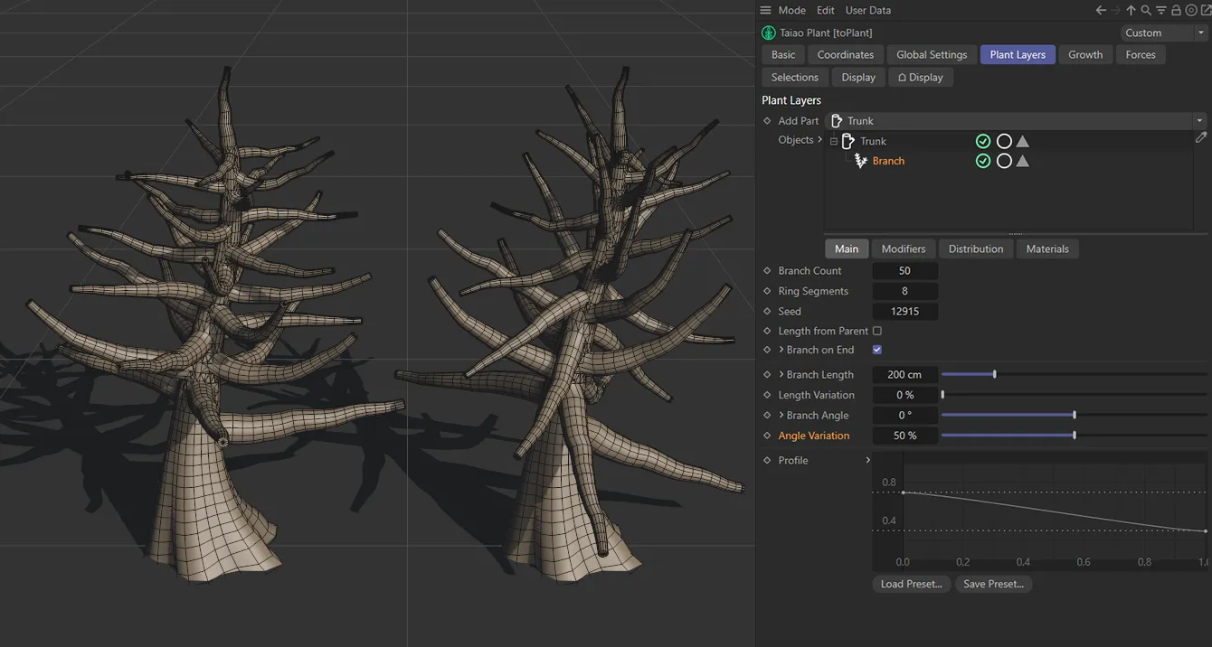
The tree on the left has an Angle Variation value of 0 (zero) %, whilst on the right there is a 50% Angle Variation setting.
Profile
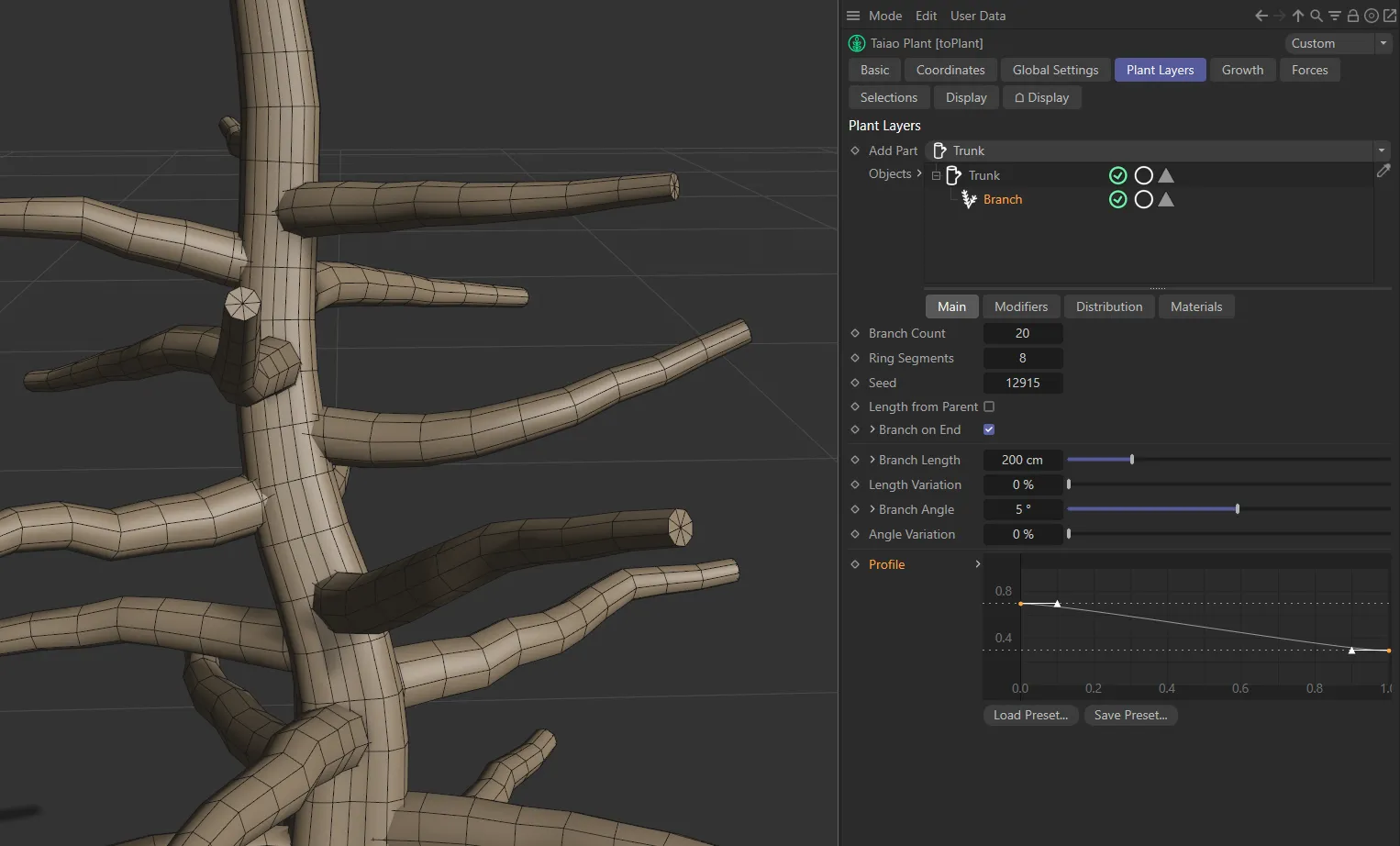
Section titled “Profile”The shape of the branch is set with a default curve, so that branches are wider at the trunk and narrow towards the tip.
It is possible to move this, to make your own setting by manipulating the spline curve.
In this animation, the Profile spline is being manipulated, to drive the branch angles.
Modifiers tab
Section titled “Modifiers tab”Modifier
Section titled “Modifier”These settings give you the ability to deform and twist your branch.
The available Modifier types are: Furling, Turbulence, Twist, Gravity, Aim, Profile and Displacer.
Each comes with its own parameter settings.
Modifier Stack
Section titled “Modifier Stack”The hierarchical list of modifiers affecting your Branch layer.
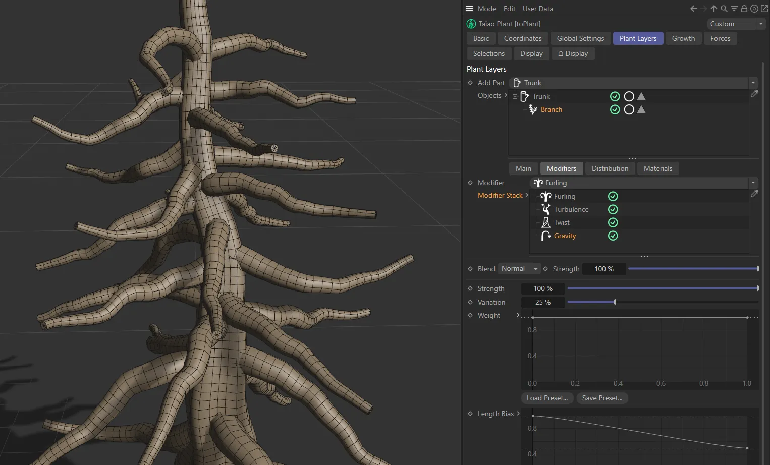
The branches, in this image, have a four different modifiers, stacked up, all affecting the Branch layer.
The modifiers each come with Blend and Strength settings in common.
Set as Normal, by default, the slider controls the intensity of the modifier, blending its effects with the effects of any other modifiers that you have in the scene.
Setting it to 0 (zero) % will eliminate any effect the modifier might have.
Setting it to 100% will show the full effect.
The other options are: Min, Subtract, Multiply, Max and Add.
Normal
Section titled “Normal”In Normal mode, there is no blending happening.
The hierarchy in the Modifier Stack determines which modifier is being enabled, with the last in ‘the tree’ overriding the ones above it.
Analyzes the modifiers and uses the lowest value for each point to give the result.
Subtract
Section titled “Subtract”In this mode, the value of the modifier is subtracted from the value of the one above it.
Multiply
Section titled “Multiply”Here, the modifiers’ values are multiplied and the results give the deformation.
Analyzes the modifiers and uses the highest value for each point to give the result.
This mode takes the values from a modifier and adds them to the values of others in the scene to give the result.
Strength
Section titled “Strength”Increasing or decreasing the level on the Strength slider will raise or lower the strength of the modifier highlighted, allowing any other modifier in the scene to be apparent.
Furling modifier
Section titled “Furling modifier”The Furling settings mimic the natural curling that can occur in plants as they grow.
Angle, Variation
Section titled “Angle, Variation”Increasing this slider will curl the branches in one direction and decreasing it will curl the branches in the other.
The Variation parameter will apply a variety between the branches.
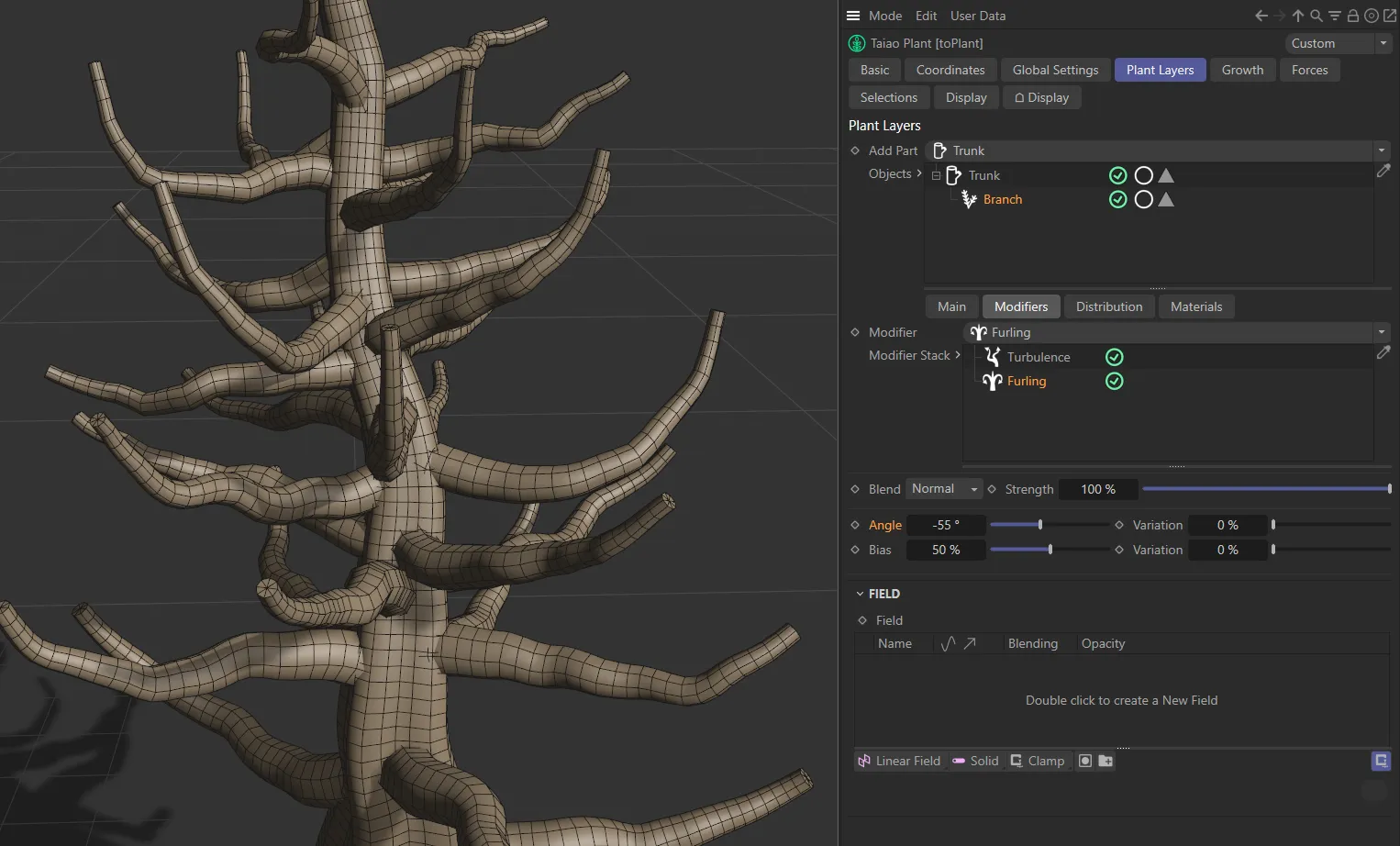
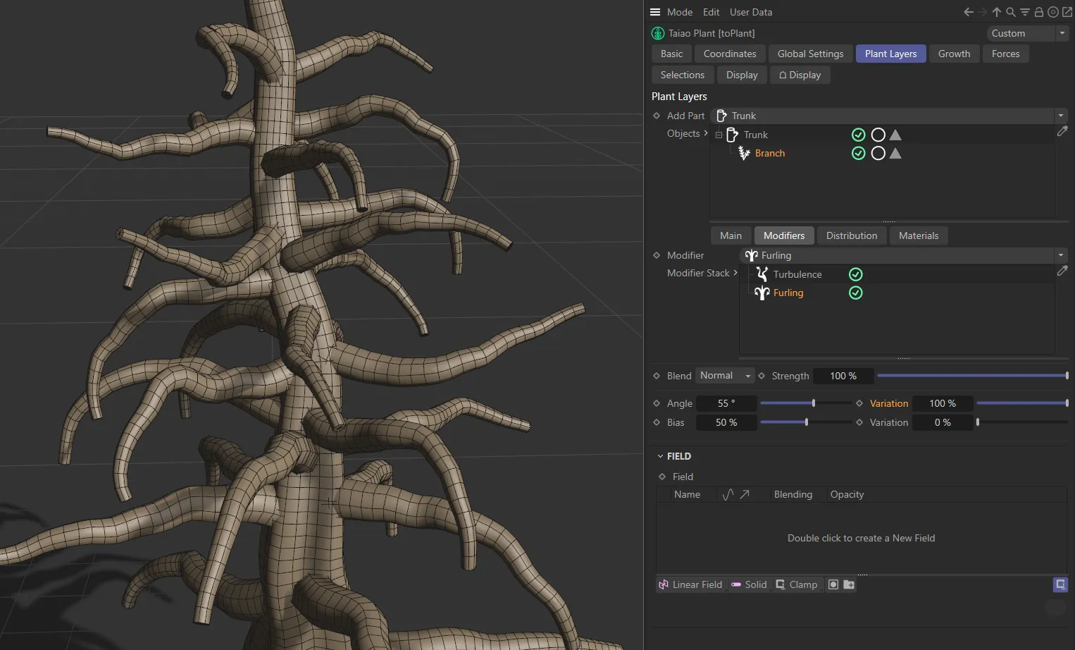
The Angle setting on the branches is (negative) -55 degrees.
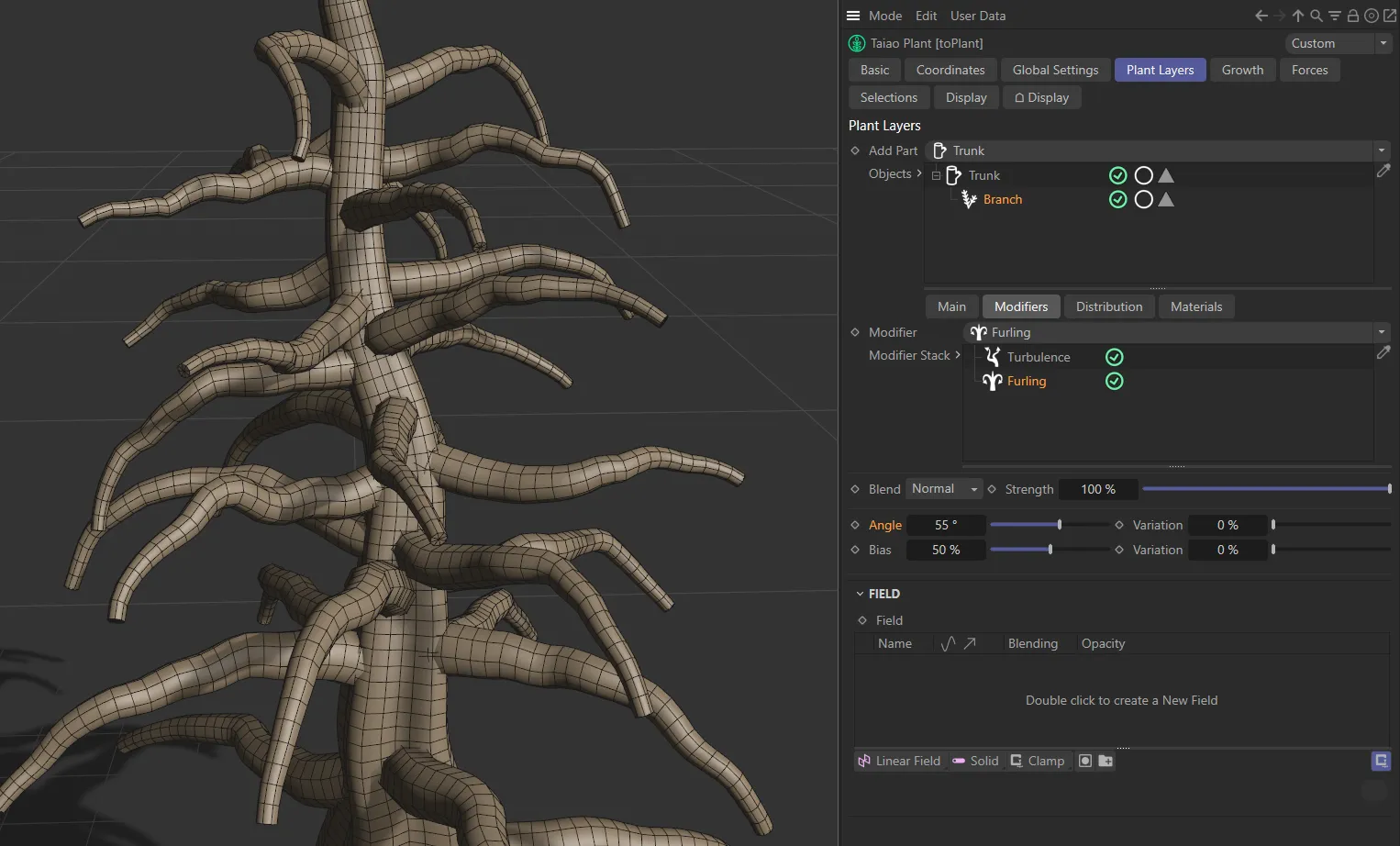
In this second image, the Angle is now set at 55 degrees.
In this final image, the Angle remains at 55 degrees, but the Variation is now set to 100%.
Bias, Variation
Section titled “Bias, Variation”This dictates where on the branch furling takes place.
At the default setting of 50%, furling occurs from the middle of the branch towards the end.
Lowering the setting sets the furling beginning nearer the trunk and raising it has the opposite effect.
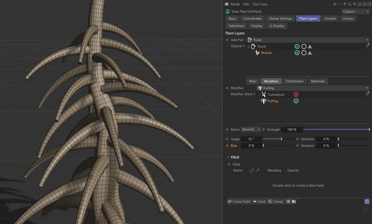
In this image, with Bias at 0 (zero) %, the entire branch is furled.
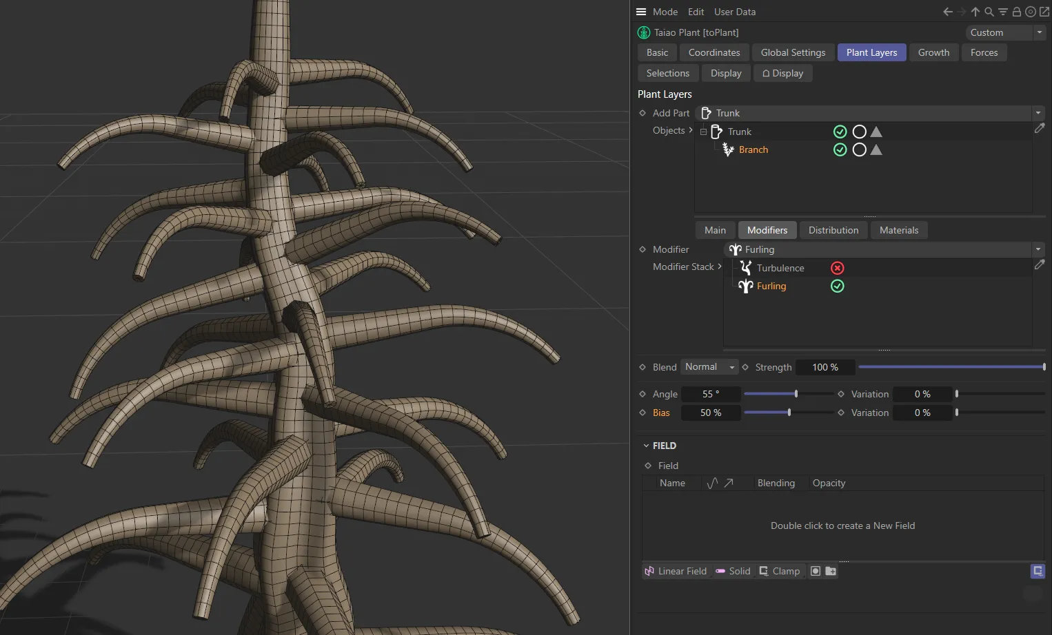
Here, the Bias is now at 50%, furling the branch from halfway along.
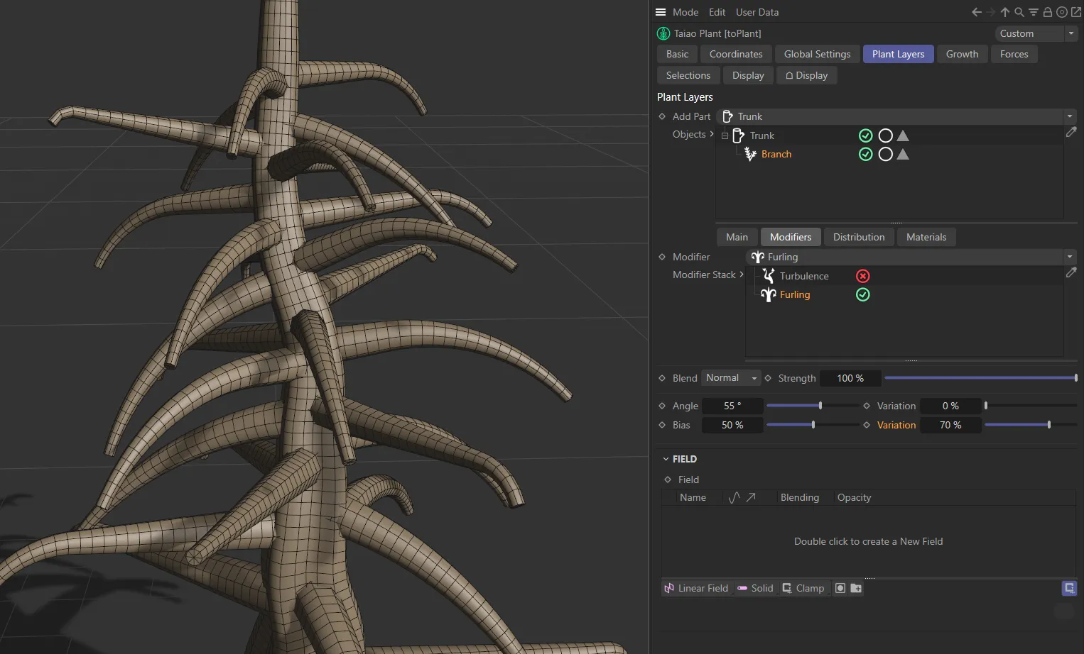
As above, the Bias is set at 50%, but here there is a Variation of 70%, giving a more organic look.
Angle Bias
Section titled “Angle Bias”This setting (added with update 2024.2) simply acts as a multiplier to the existing bend angle along the length of the branch.
The Furling modifier UI, demonstrating the Angle Bias (added with update 2024.2) parameter.
Turbulence modifier
Section titled “Turbulence modifier”Changing the Seed value will give you a different, random, look.
Turbulence
Section titled “Turbulence”Turbulence is set, at a default strength of 50%.
You can increase or decrease this, to your taste, either by using the slider to 100% or manually inputting a higher value to further increase the deformation.
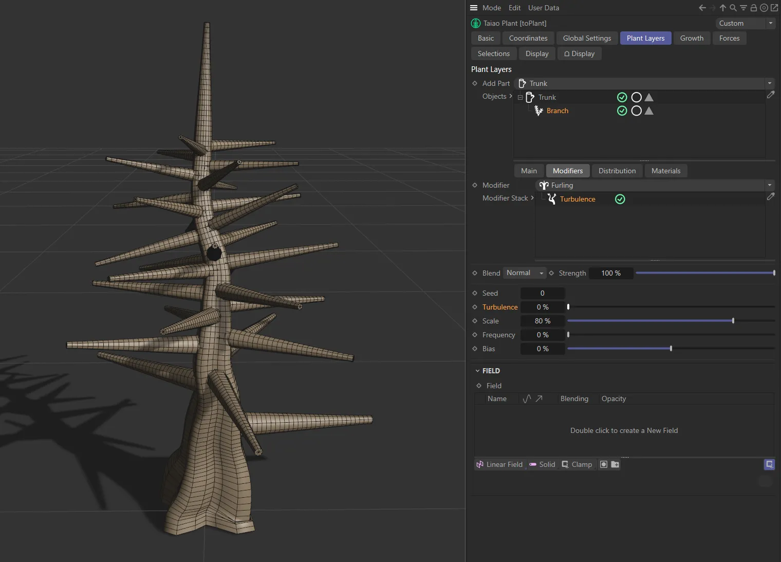
In this first image there is a 0 (zero) % Turbulence setting.
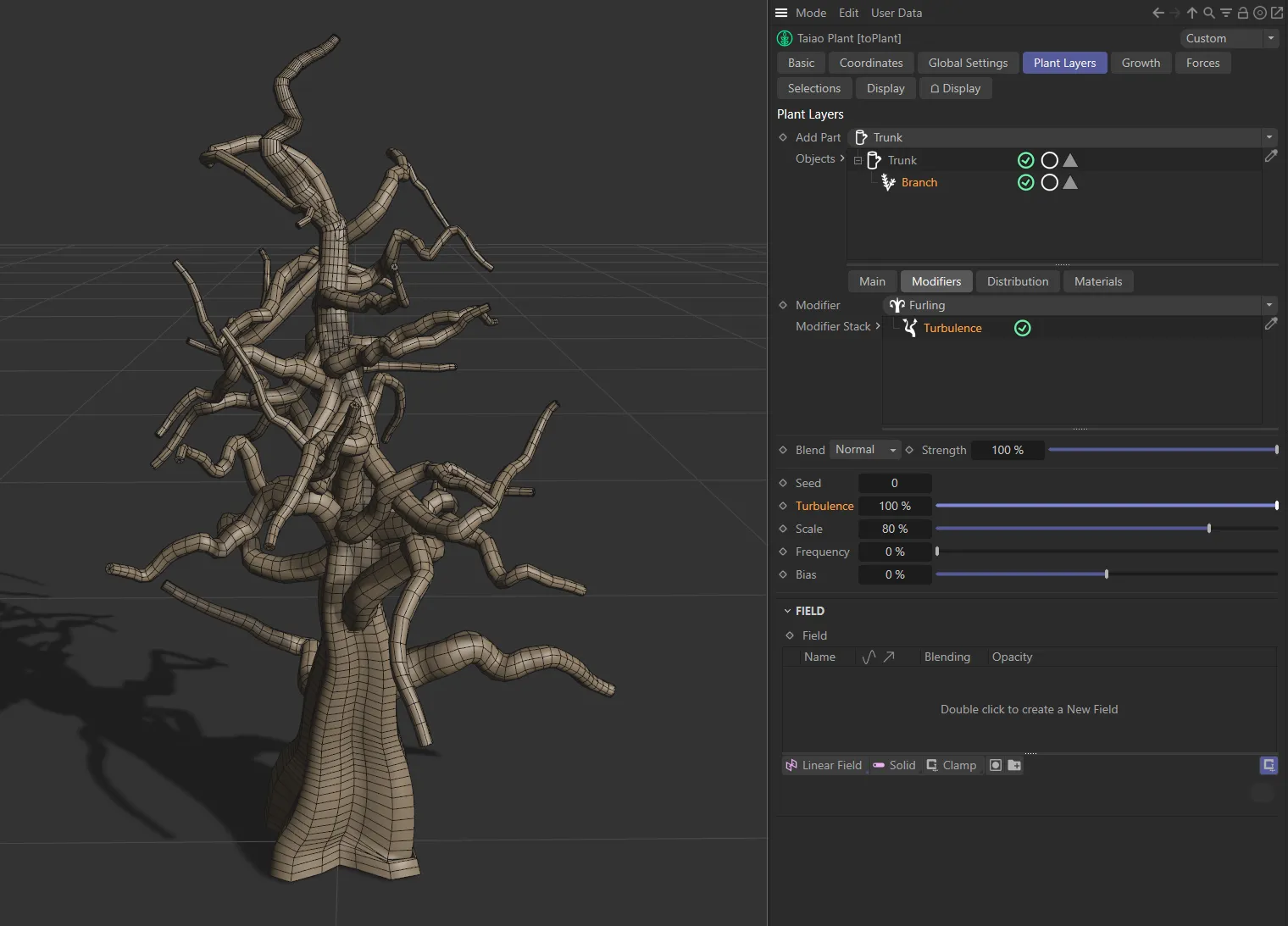
The Turbulence setting here has been manually input at a value of 100%.
This slider increases or decreases the scale of turbulence that you have set, with much more detailed noise deformation at lower value settings.
Frequency
Section titled “Frequency”Sets the rate at which the turbulence animates.
At 0 (zero) %, the turbulence will remain static.
The Bias slider setting dictates where along the branch the deformation begins.
At the default setting of 0 (zero) %, the entire branch is affected by the turbulence and at 100% there is no turbulence at all.
A negative bias value will isolate the deformation to affect the base of the branch, whereas a positive bias value will isolate the deformation to affect the tip(s) of the branch(es).
Twist modifier
Section titled “Twist modifier”Twisting of the branch is controlled by this slider, with higher values available by manual input.
Variation
Section titled “Variation”This percentage slider will vary the effect of the twisting from branch to branch.
Gravity modifier
Section titled “Gravity modifier”These settings simulate the effects of gravity on the branches.
Strength
Section titled “Strength”You can use the slider to affect the branches in the strength of the gravitational pull.
Variation
Section titled “Variation”Adds more, or less, variety in how the different branches are affected.
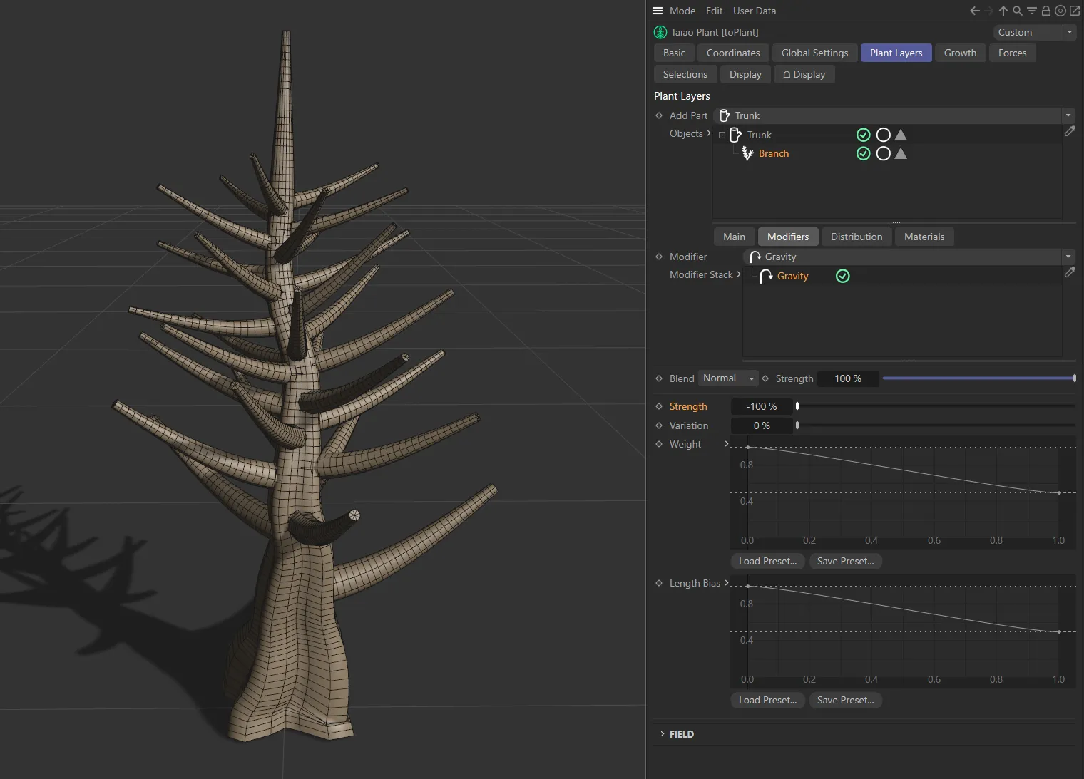
Strength set at (negative) -100%.
Here, the Strength value is 100%, giving maximum gravity on the branches.
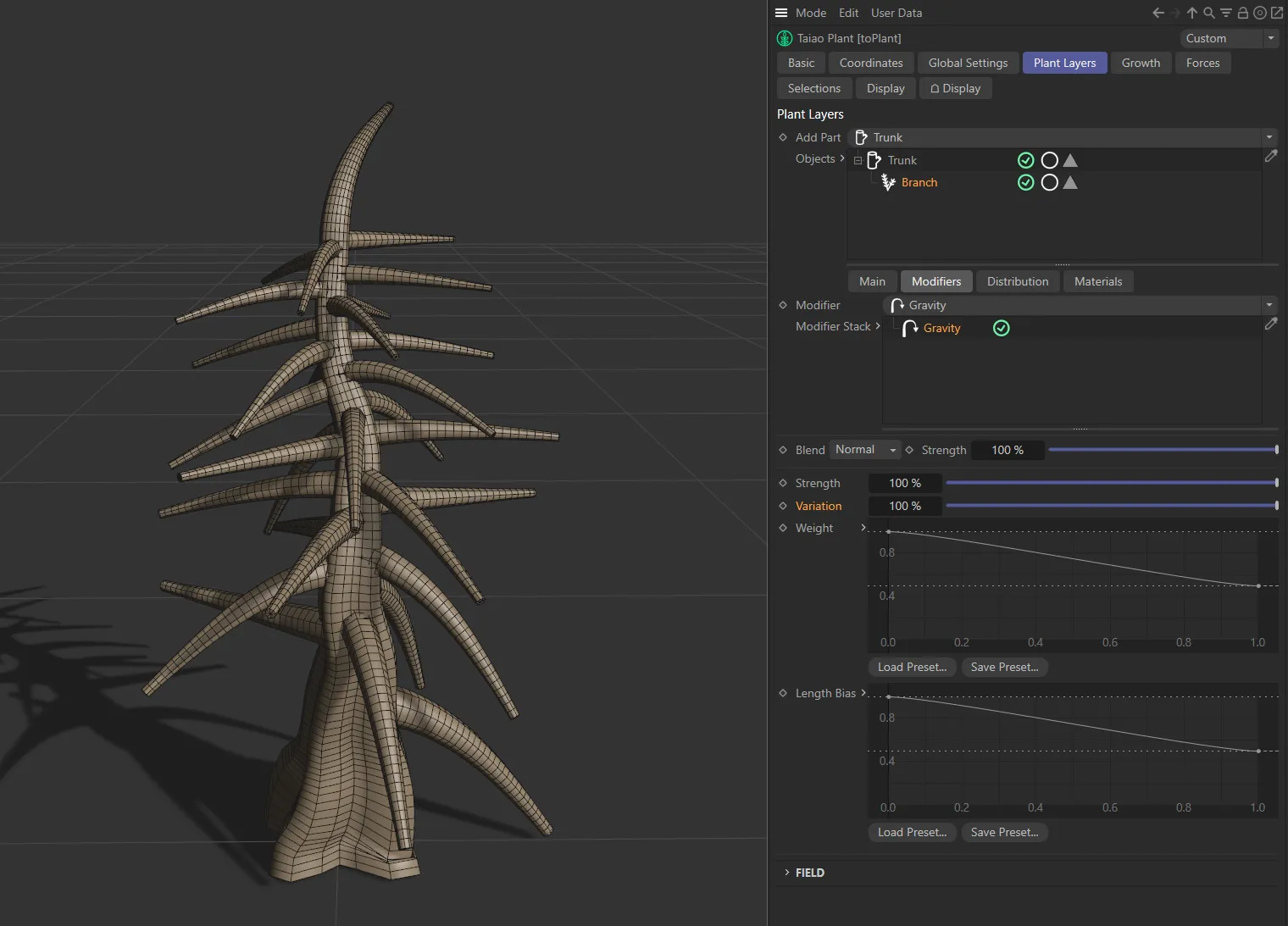
In this final image, the Strength is still at 100%, but there is a Variation of 100%, meaning the gravity setting is different for each branch.
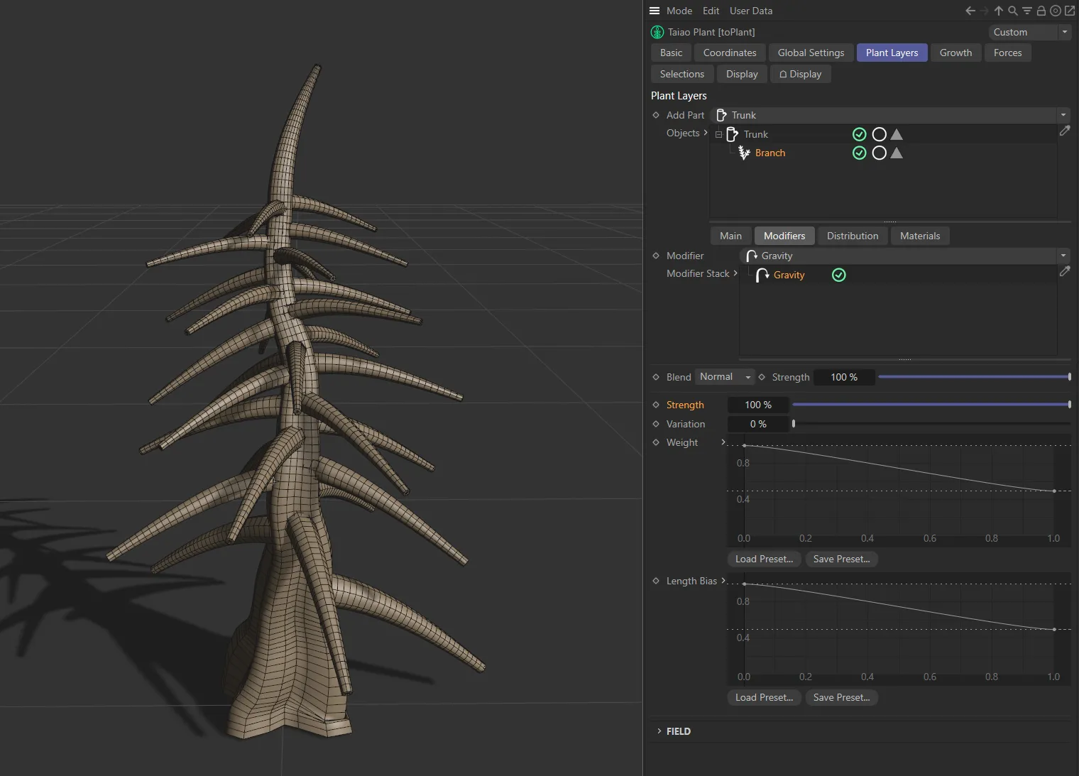
Weight
Section titled “Weight”This enables you to map the gravity strength along the length of the branches themselves.
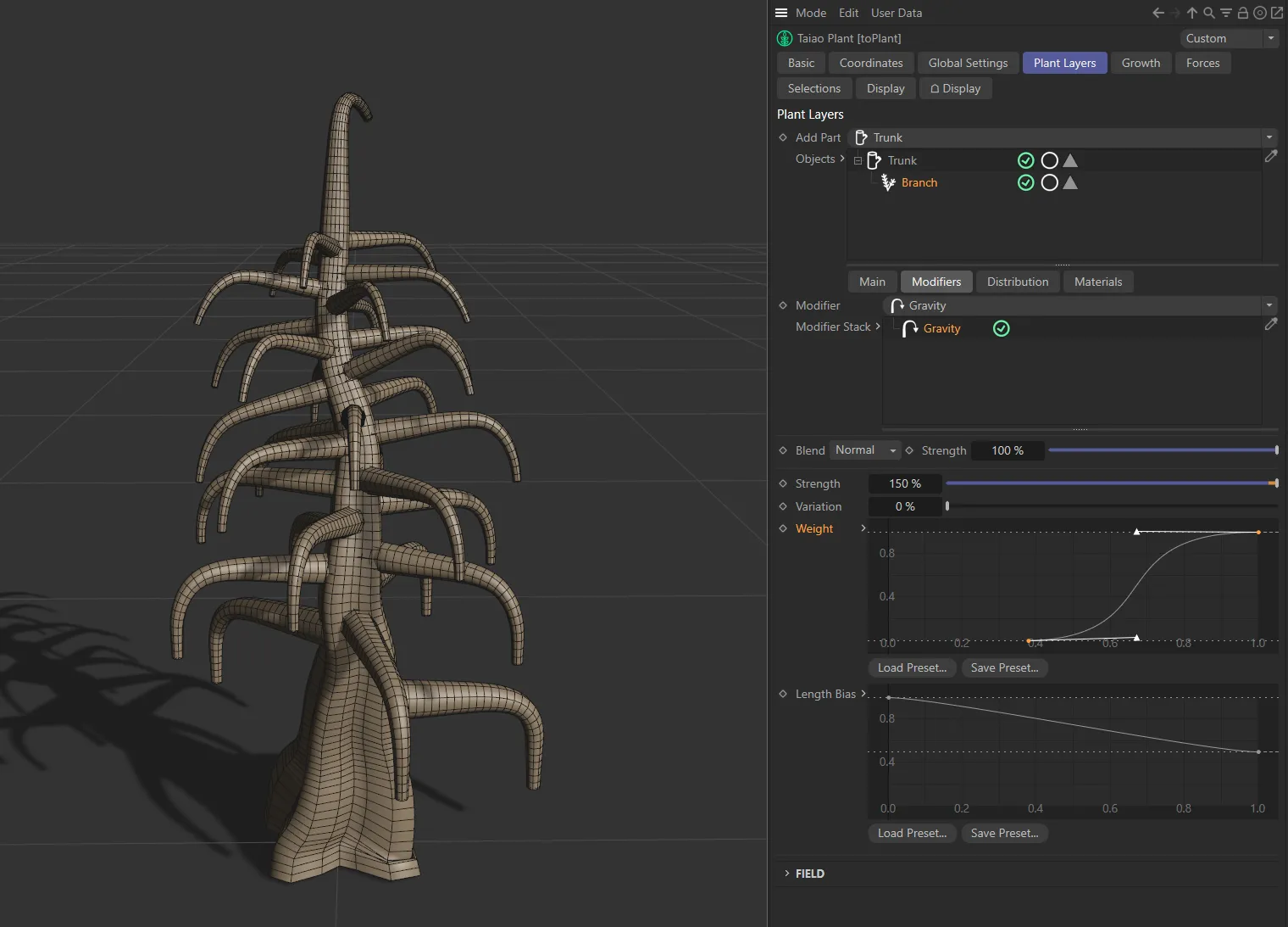
The image above shows the Weight spline curve increasing sharply, from minimum to maximum along the second half of the X-axis (which represents the branch length) affecting gravity towards the end of the branches.
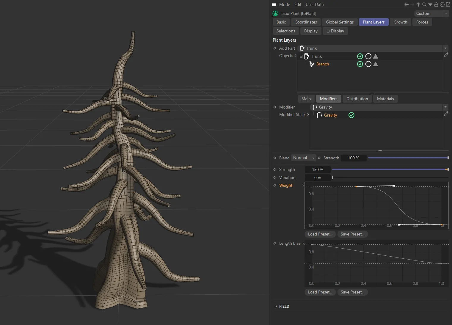
In this image, the inverted weight curve is producing rising branch tips.
Length Bias
Section titled “Length Bias”Dictates the gravity along the length of the parent (Trunk) layer.
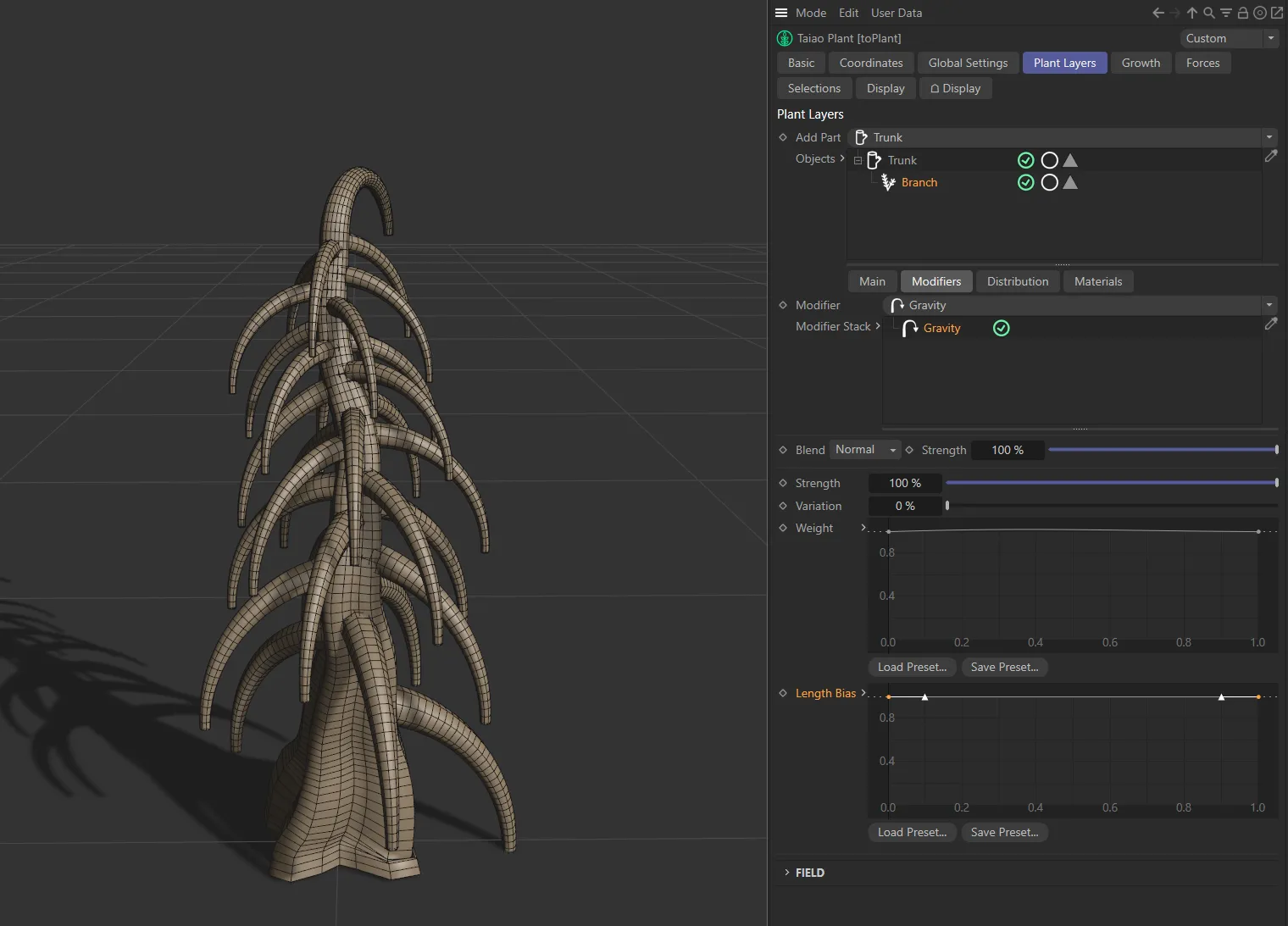
The image here, with Length Bias spline points at the maximum Y-axis level, demonstrates gravity affecting each branch, at the 100% Strength setting.
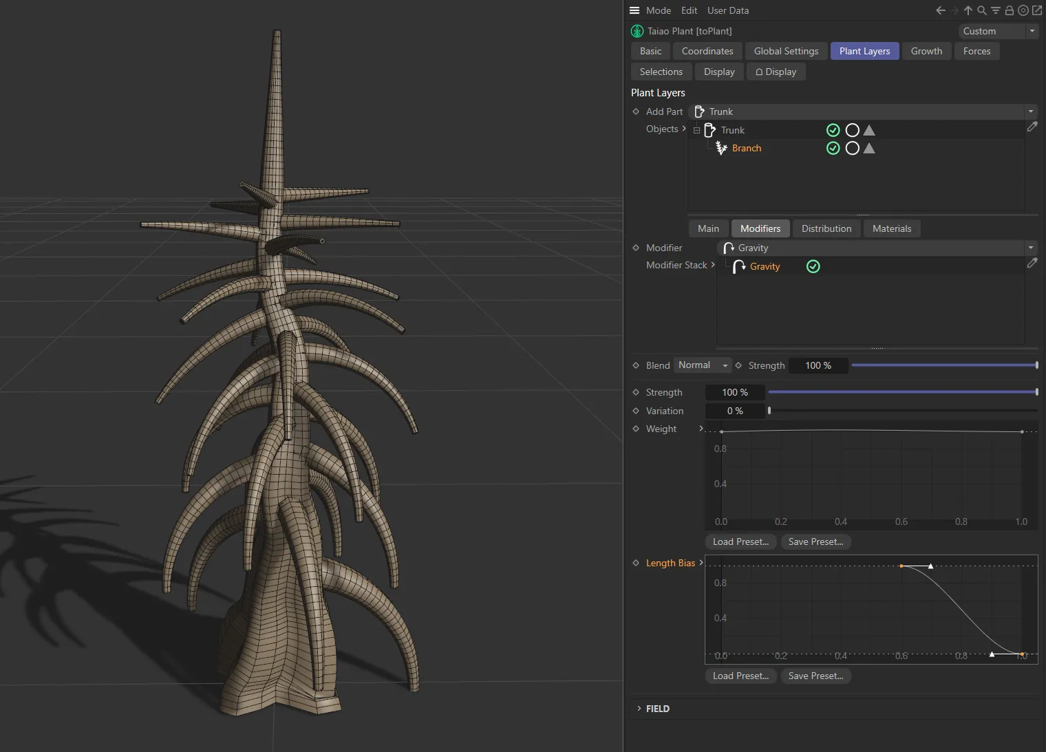
In this second image, the custom Length Bias curve decreases branch gravity along the trunk length (represented by the X-axis on the Length Bias setting).
Aim modifier
Section titled “Aim modifier”This modifier aims the plant layer in a set direction.
Direction
Section titled “Direction”Set as Y+ (World), by default, this aims the Branch layer along a direction on the named axis.
The alternatives are Y- (World), Y+ (Local), Y- (Local) and Object.
Object
Section titled “Object”Drop a scene object into this field for it to become a target for the Branch layer.
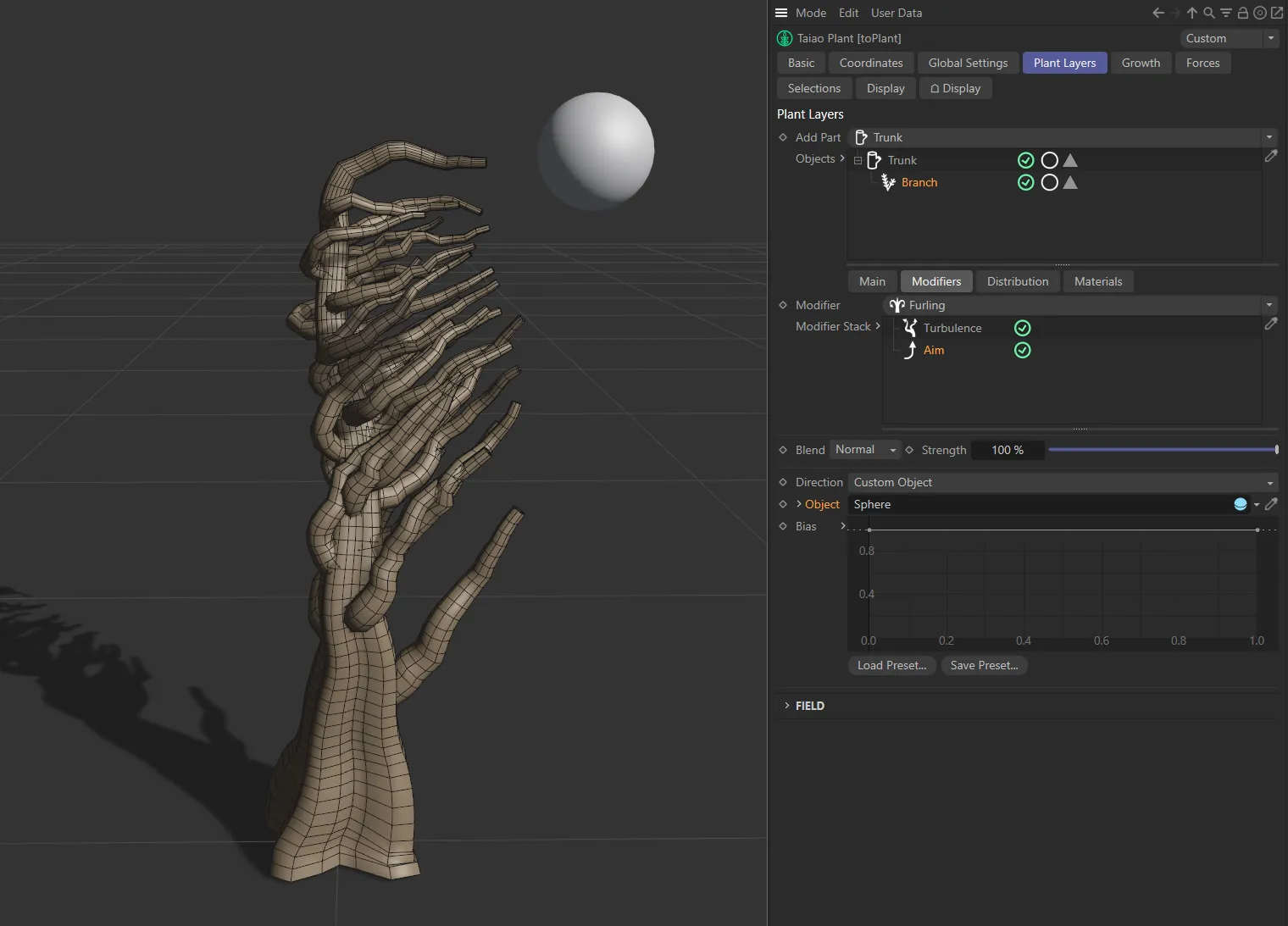
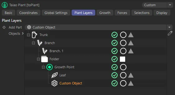
With the Aim modifier enabled, the Direction setting here is Custom Object and a Sphere has been dropped into the Object field as a target for the branches to aim at.
Use this spline curve to customize the aim along the length of the layer.
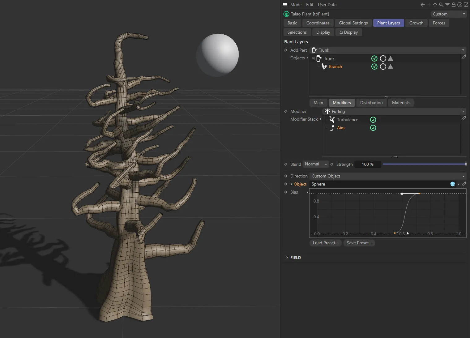
These are the same settings as above, except for the Bias curve setting, which has been adjusted so that only the branch tips are aiming towards the Sphere.
Profile modifier
Section titled “Profile modifier”This modifier allows you to introduce a custom spline to shape the Branch layer.
Profile Spline
Section titled “Profile Spline”Dragging and dropping a spline into the Profile Spline link field will result in the spline shape being used to create the Branch layer.
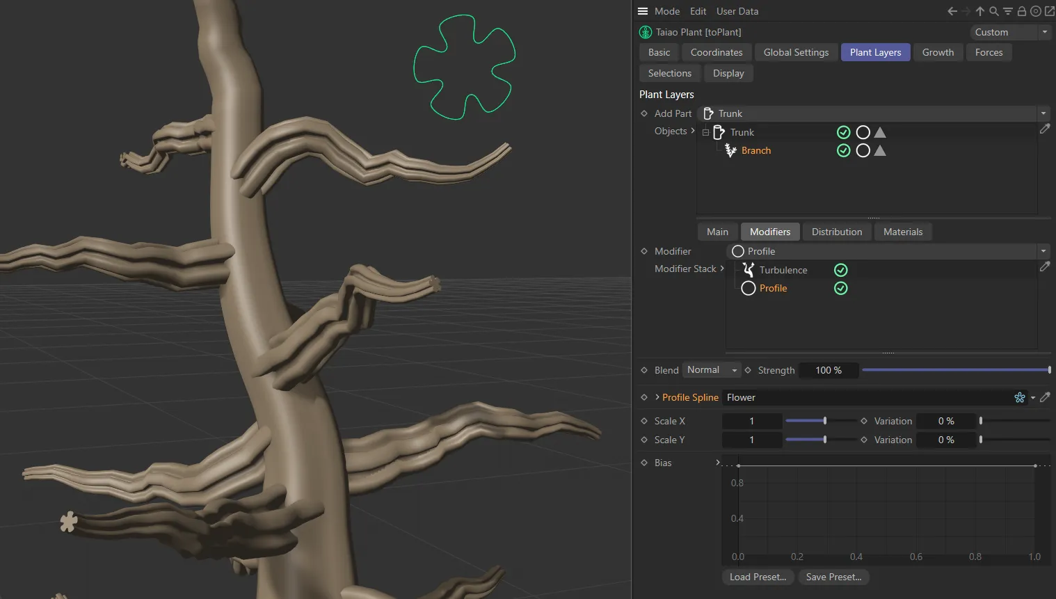
The image above illustrates the Profile modifier, with the Flower spline (shown in green) having been dropped into the Profile Spline field, shaping the Branch layer.
Scale X, Variation
Section titled “Scale X, Variation”Scales the trunk on the X-axis of the layer.
Variation allows you to apply some variation over the length of the branch.
Scale Y, Variation
Section titled “Scale Y, Variation”Scales the trunk on the Y-axis of the layer.
Variation allows you to apply some variation over the length of the branch.
Adjusting the spline curve gives you control over the shaping of the branch, with maximum adherence to the Profile Spline at the top of the Y-axis and the X-axis representing the branch length.
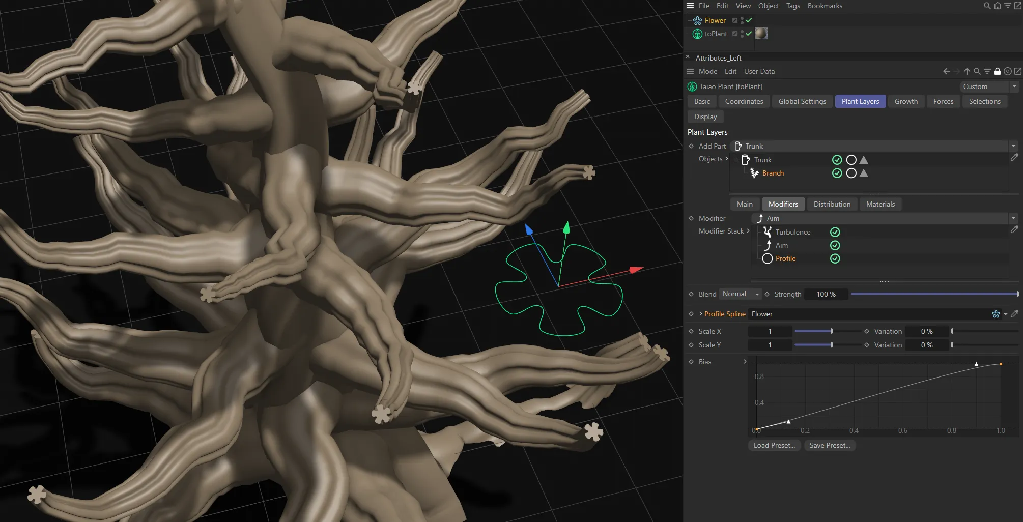
With the same settings as above, except the Bias spline curve setting has been adjusted so that the branch shapes more to the Profile Spline as it goes along its length.
Displacer modifier
Section titled “Displacer modifier”This modifier lets you bring in a Shader or a Texture to shape the plant layer.
Selecting this modifier will give you the usual additional options to be able to import your Shader or Texture into the scene, including parameters for Channel and Tolerance settings.
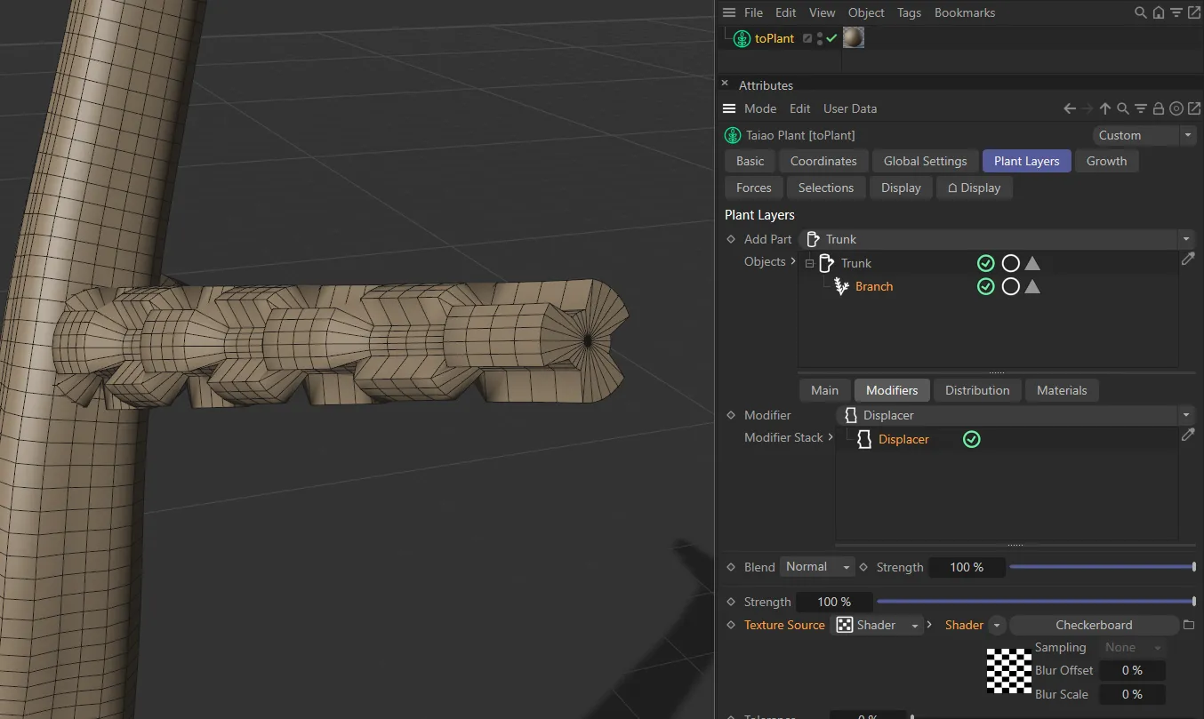
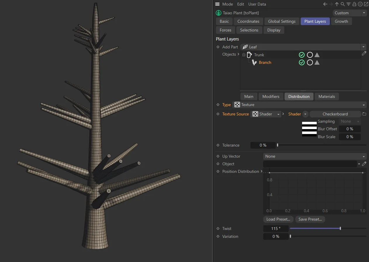
Here, the Displacer modifier has a Texture Source of Shader, with a Checkerboard shader applied.
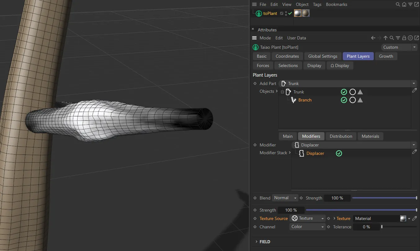
In this second image, the Texture Source is set to Texture. The Cinema 4D material tag - coloring the branch - is also being used to displace the branch, where black gives no displacement and white gives full displacement.
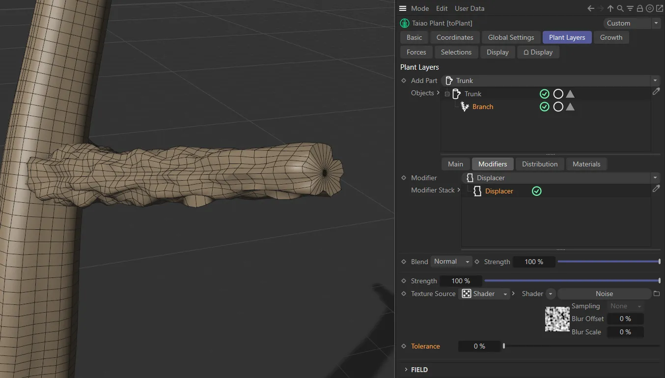
The Texture Source is Shader, here, with a Noise shader displacing the branch.
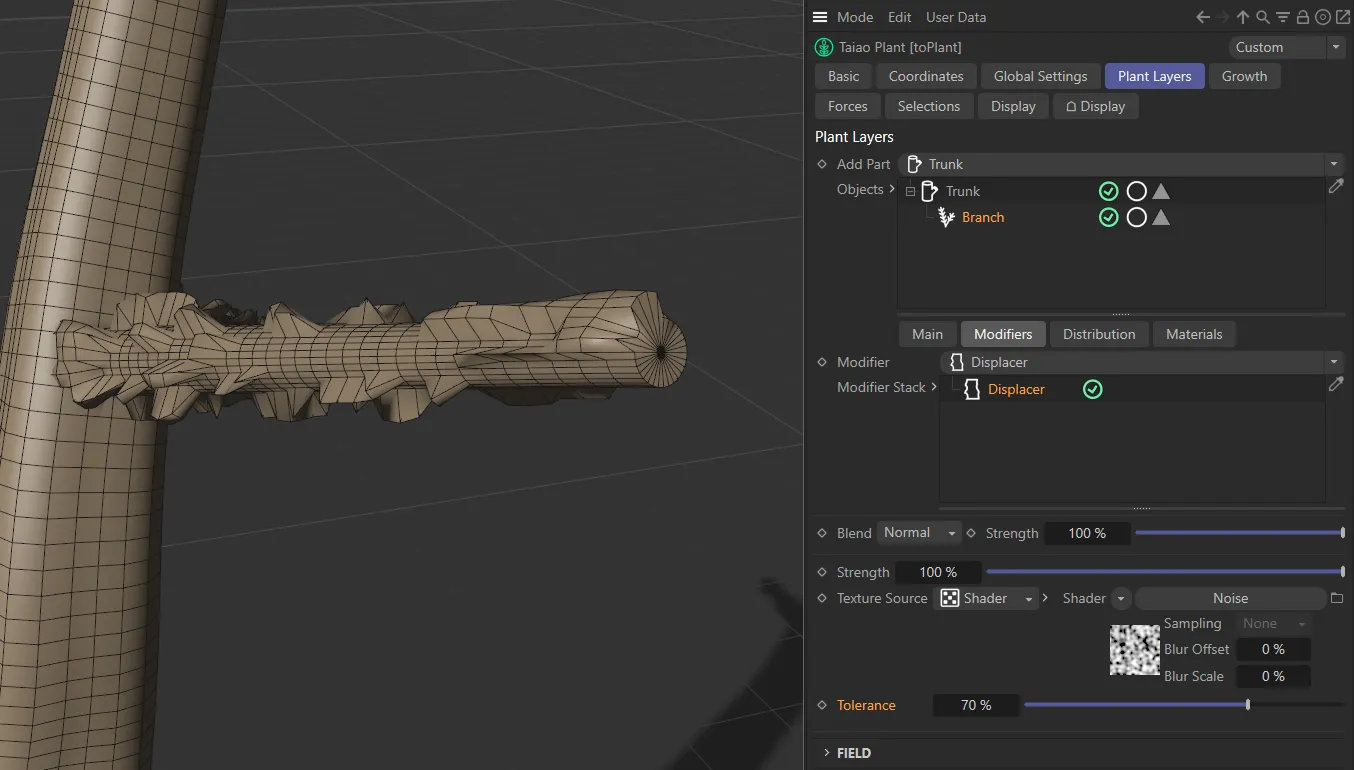
This final Displacer image shows the Noise shader being restricted by a Tolerance value of 70%.
You have access to the usual field objects, which can be used to drive the modifiers in your scene.
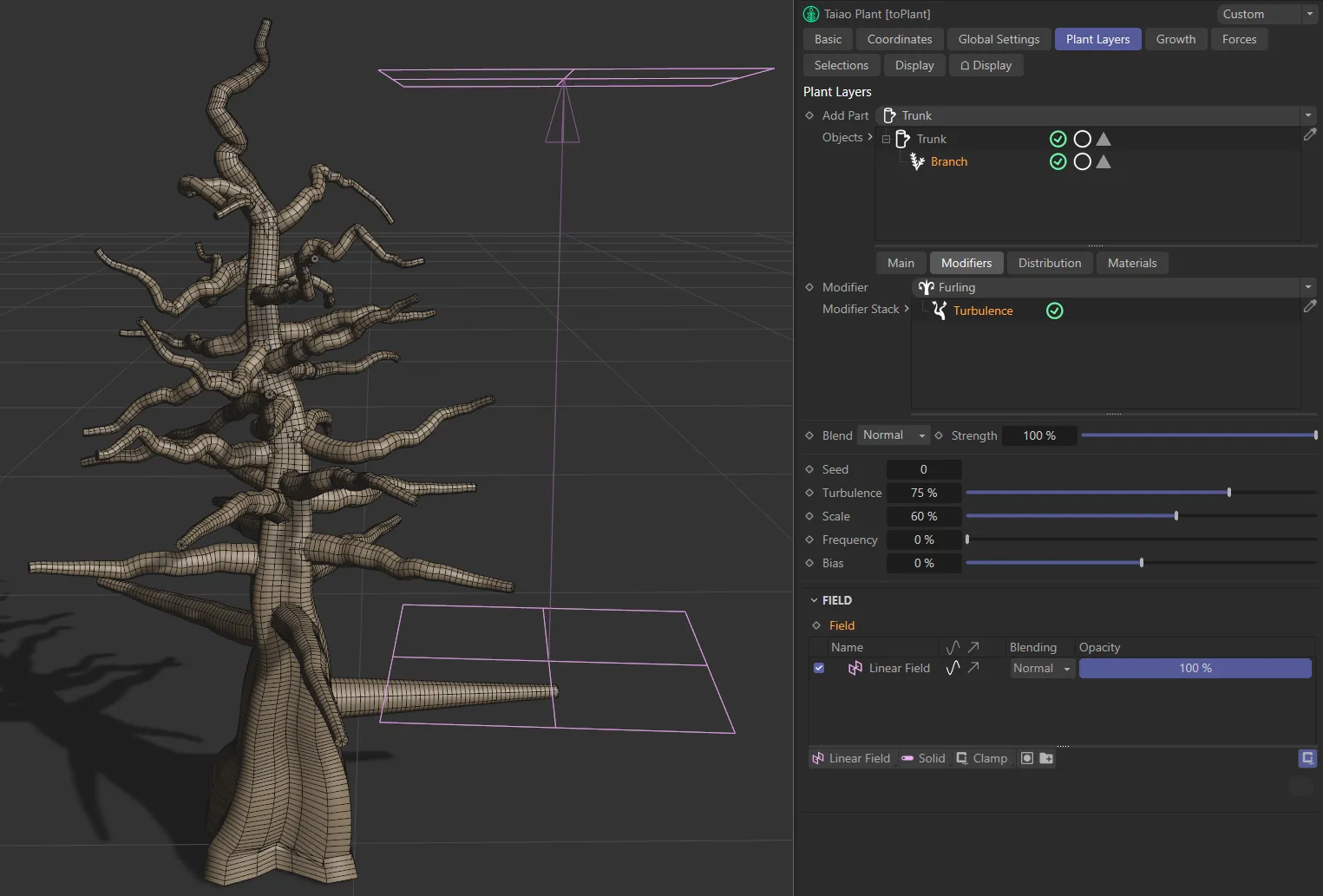
Here, a Linear field is being used to give more turbulence higher up the tree.
Distribution tab
Section titled “Distribution tab”Powerful settings, that will give you degrees of control.
By default, this is set to Spiral, but there are nine settings: Random, Alternate, Distichous, Unilateral, Spiral, Whorled, Decussate, Tricussate and Texture, all of which imitate real-life, natural variations.
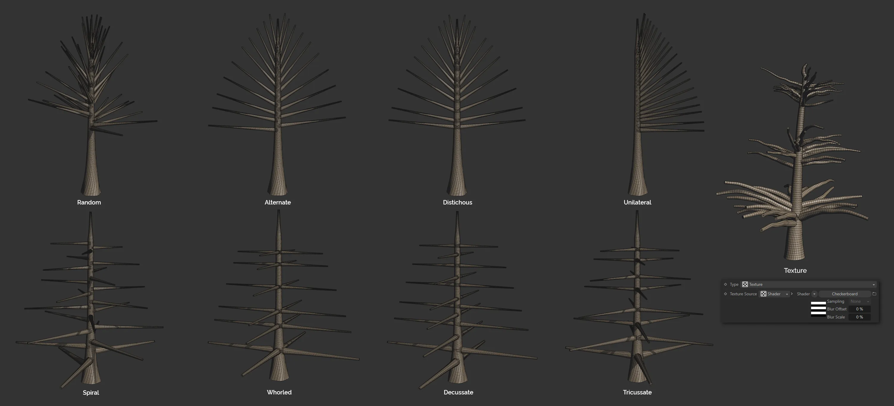
Image to show the nine Type settings available in the Distribution tab settings.
Random
Section titled “Random”Randomly generates and distributes the branches.
Changing the Seed generates a new random pattern.
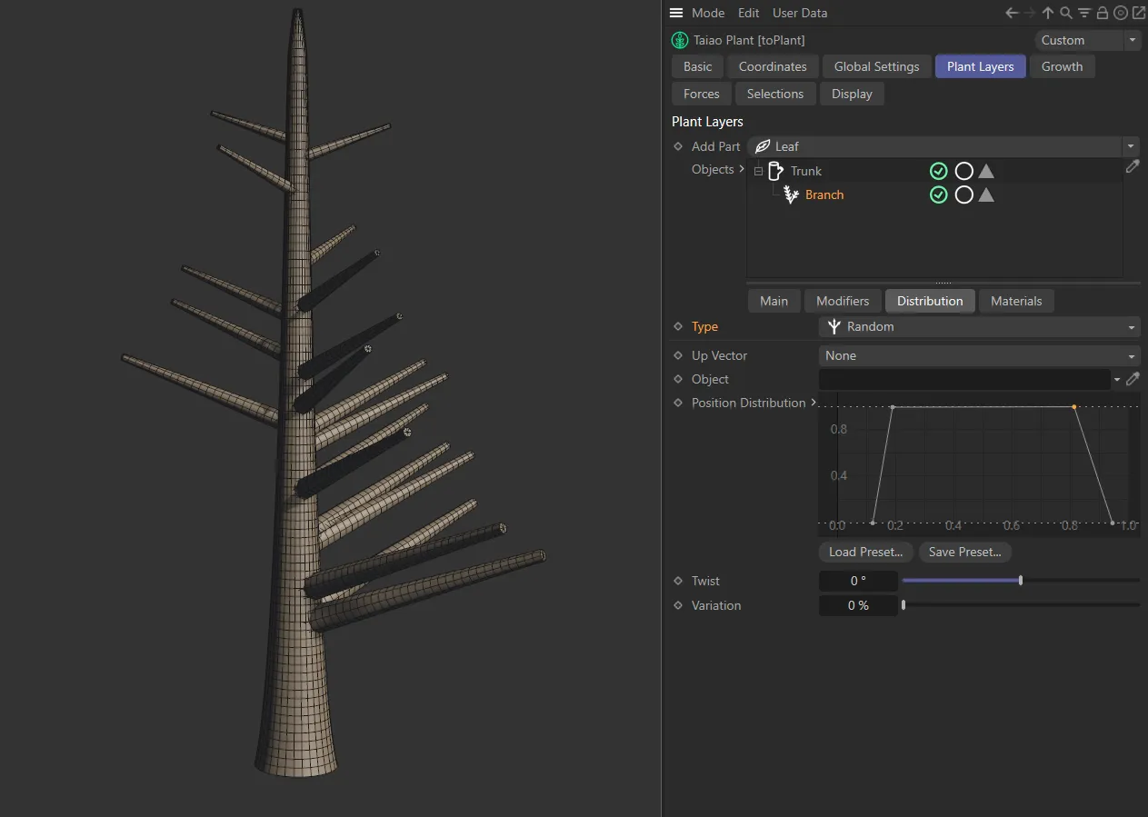
Type set to Random.
Alternate
Section titled “Alternate”Alternating distribution of branches.
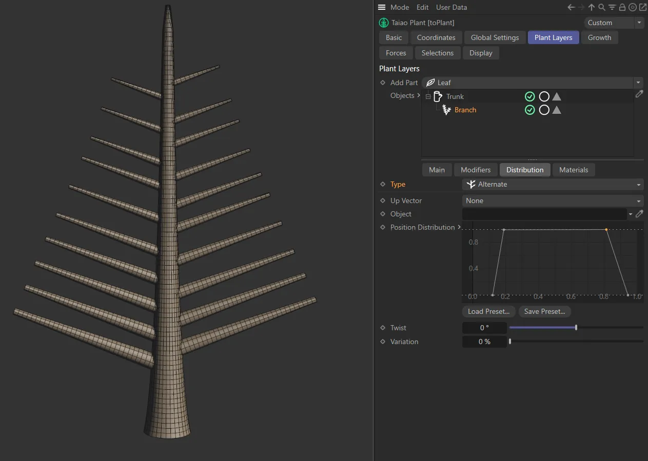
Branches in the Alternate setting.
Distichous
Section titled “Distichous”Giving pairs of branches all the way up the trunk.
This setting opens up the Branch Count parameter.
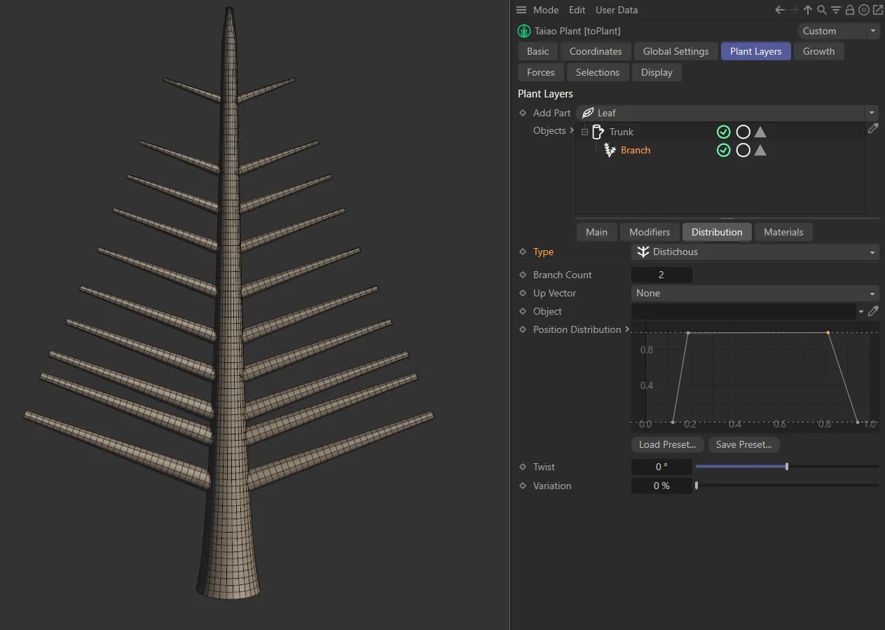
The Distichous setting.
Branch Count
Section titled “Branch Count”You can change the number of branches, from the default setting of 2, so that there will be more branches on each layer of the trunk.
This setting will rely on your Branch Count setting in the Main tab, which has set the maximum number of branches on your tree.
Unilateral
Section titled “Unilateral”This gives you branches up one side of the trunk only.
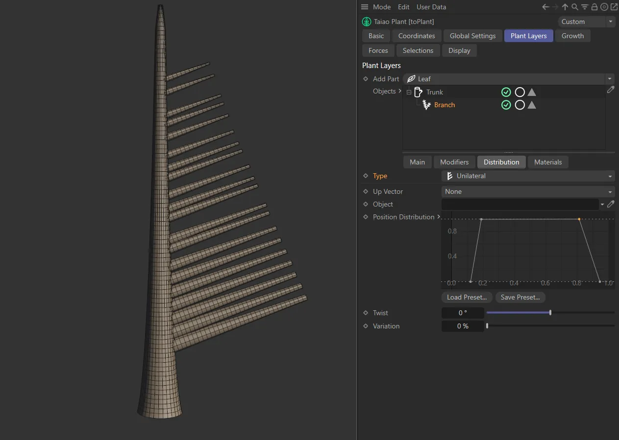
The Unilateral setting.
Spiral
Section titled “Spiral”The branches grow up the trunk in a spiraling pattern.
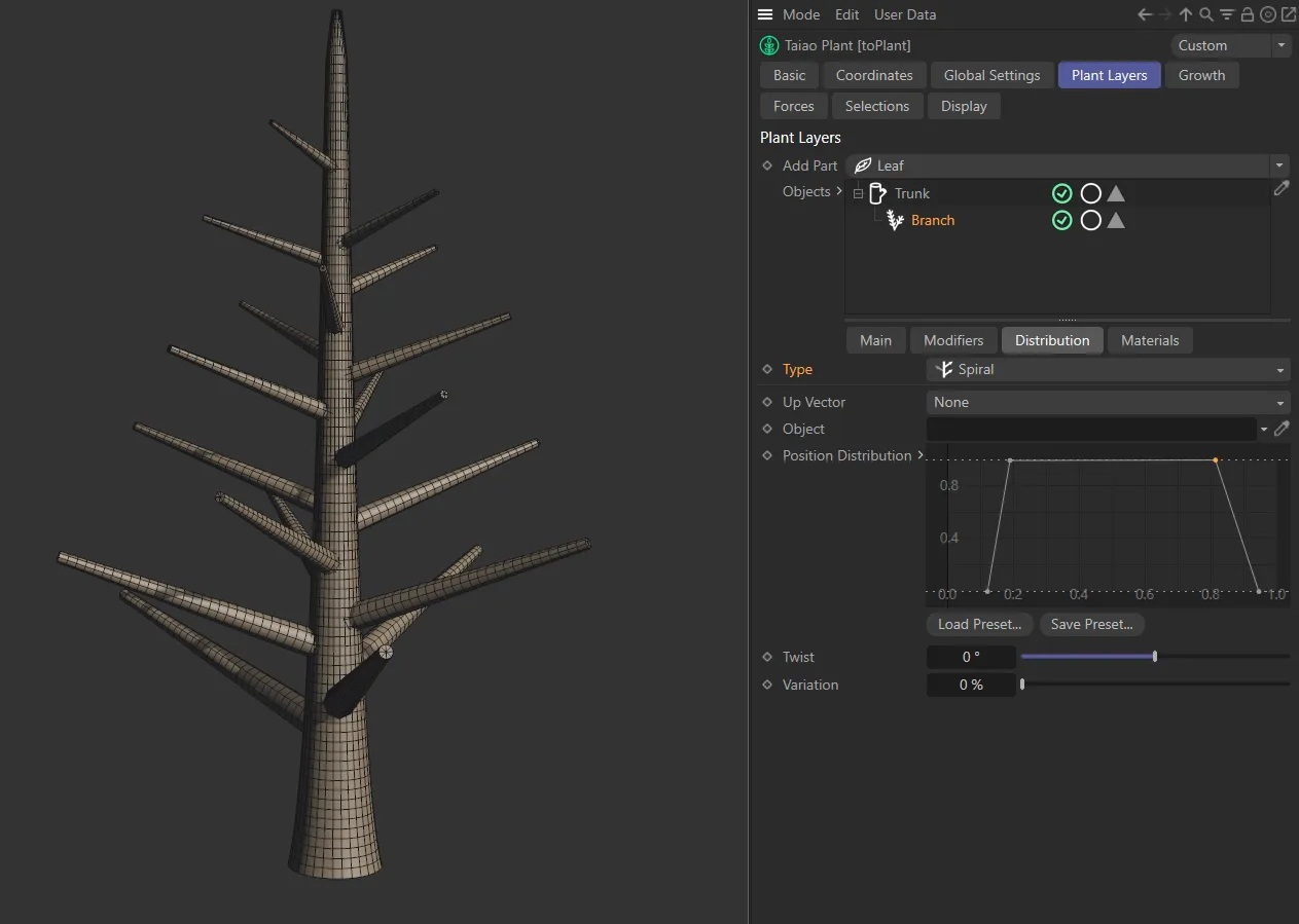
Branches set in the Type setting of Spiral.
Whorled
Section titled “Whorled”Diamond-shaped branches, which again can be increased, or decreased in the Branch Count setting.
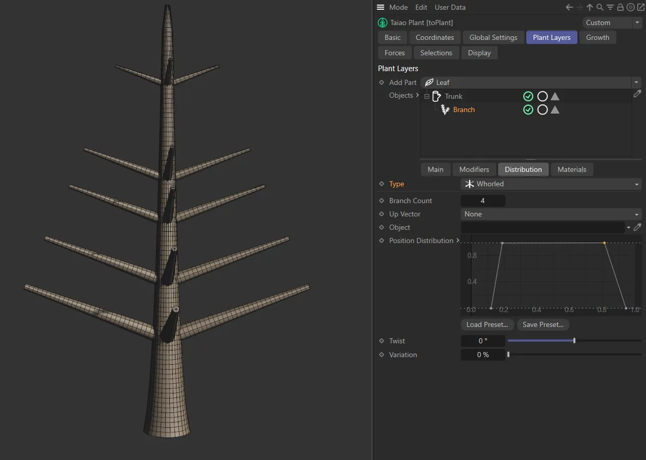
Whorled setting.
Decussate
Section titled “Decussate”This gives alternating pairs, by default, which can be changed in the Branch Count setting.
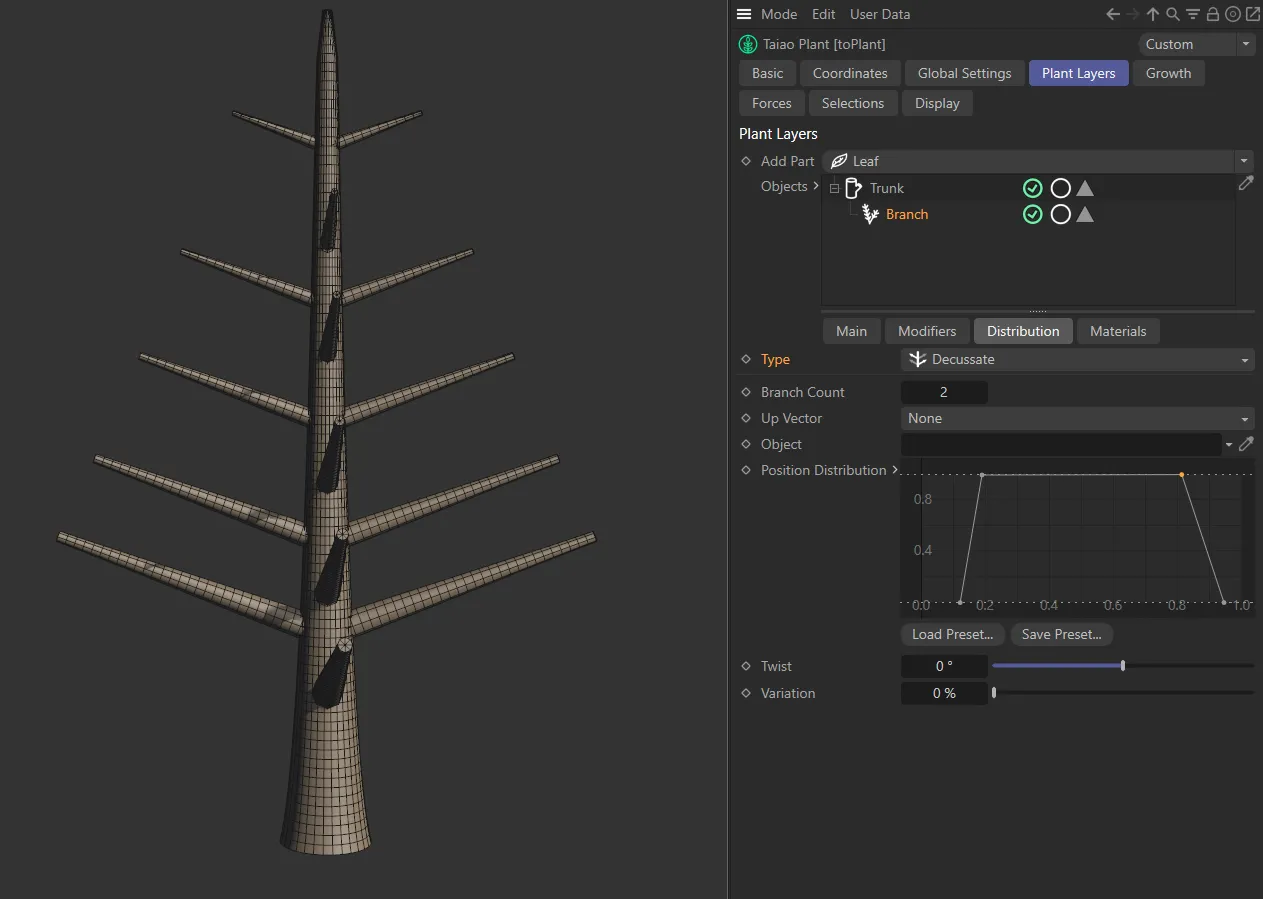
The Decussate setting.
Tricussate
Section titled “Tricussate”Alternating, once again, but this time with three branches on each layer of the trunk.
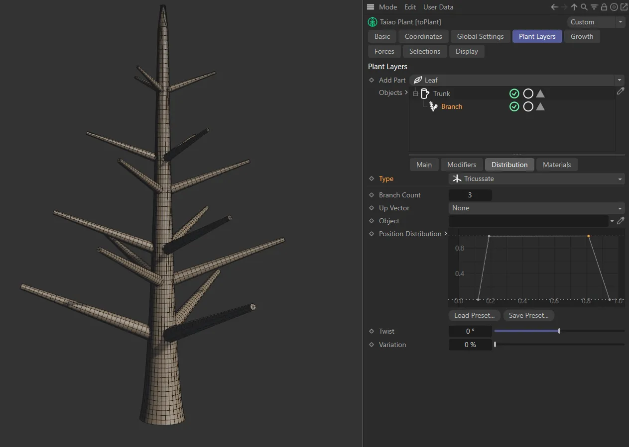
Tricussate setting.
Texture
Section titled “Texture”You can now use a Shader or a Texture to control the distribution of your branches.
Selecting this Type will give you the usual additional options to be able to import your Shader or Texture into the scene, including parameters for Channel and Tolerance settings.
In this image, the Type setting is Texture, with a Checkerboard shader. The U Frequency is set to (zero) 0 and the V Frequency is set to 3, giving a vertical striping effect, where white represents branches and black, no branches.
Up Vector
Section titled “Up Vector”By default, this is set to None and will be driven by any settings that you have in the Angle settings for furling on the Main tab.
The other settings are: Y+ (World), Y- (World), Y+ (Local), Y- (Local) and Object.
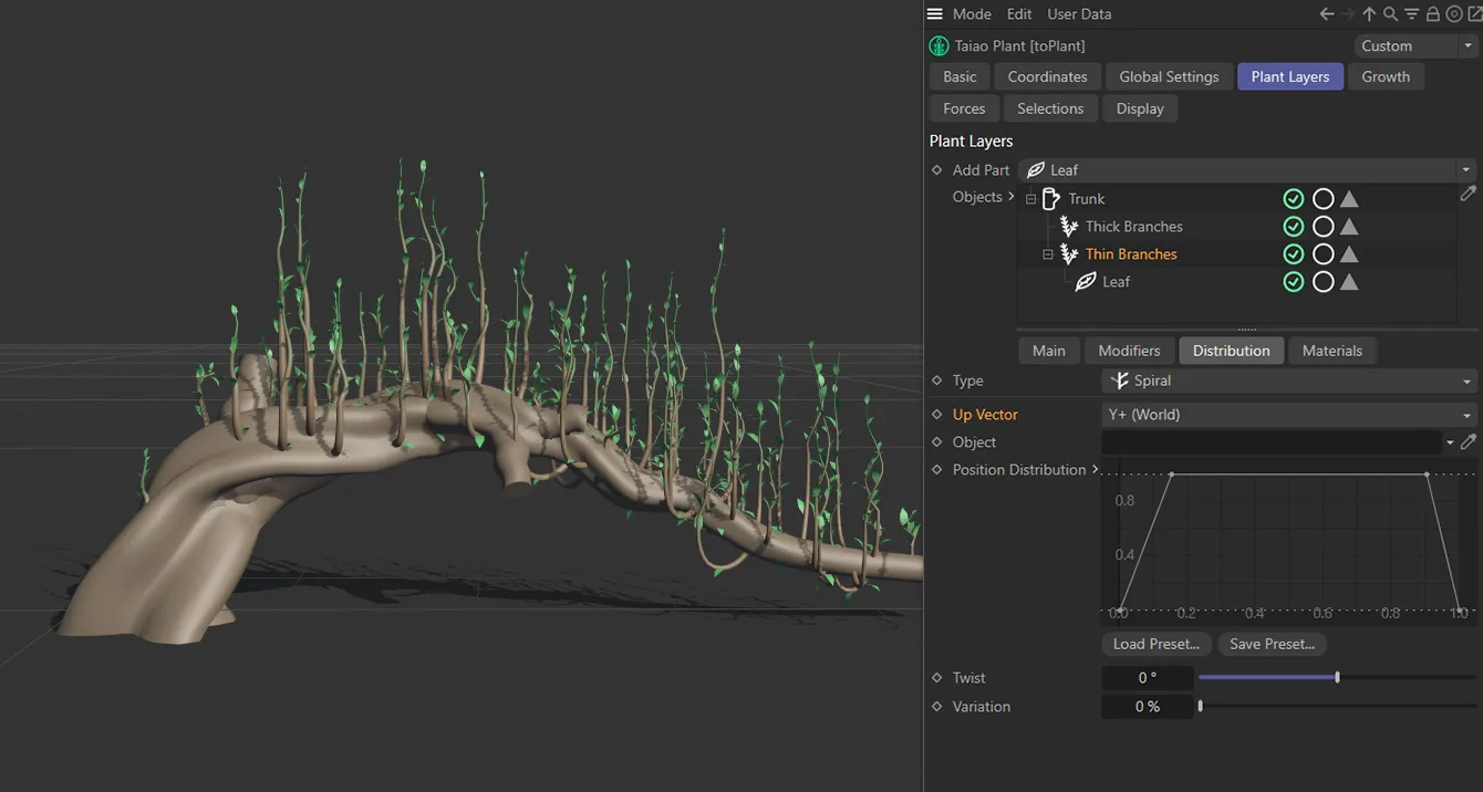
In this image, the Up Vector setting is Y+ (World), with the highlighted Branch layer reaching up in the Y+ axis.
In this mode the furling is simply driven by any settings that you have established in the Main tab.
Y+ (World)
Section titled “Y+ (World)”This uses the World axis to set the furling upwards. Even when the entire plant is rotated, the branches will still use this World Y+ axis as its guide for what constitutes upwards.
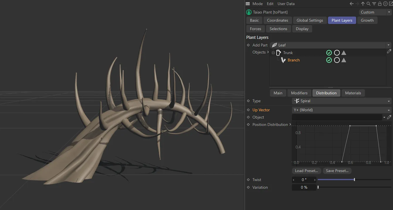
Y+ (World) vector.
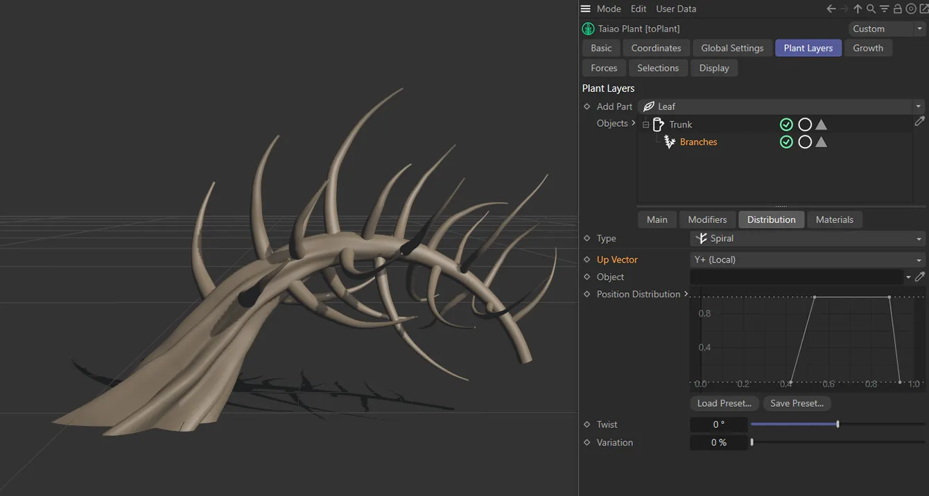
Branches set to Y+ (Local).
Y+ (Local)
Section titled “Y+ (Local)”In this setting, the branches will use the Y+ axis of the toPlant object itself, as its guide for what constitutes upwards.
Object
Section titled “Object”Alternatively, you can bring in an object, by selecting Object in the Up Vector settings, then dragging the object into the Object field and the branches will target that object in your scene.
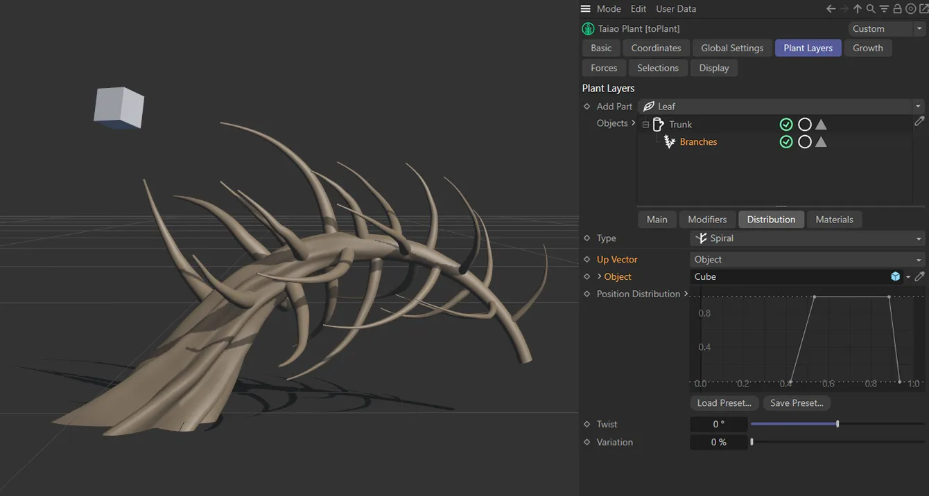
Up Vector in the Object setting, with branches targeting the Cube primitive.
Object
Section titled “Object”With Up Vector set to Object, drop your scene object into this field to set a target for the branches.
Once an object is present in this field, the usual Cinema 4D Object Properties become available by unfolding the drop-down arrow.
Position Distribution
Section titled “Position Distribution”The X-axis is, once again, the length of the parent layer (the Trunk layer) and the Y-axis is the strength of distribution.
To distribute your branches evenly along your trunk you would set a flat spline across the top of the box, as below.
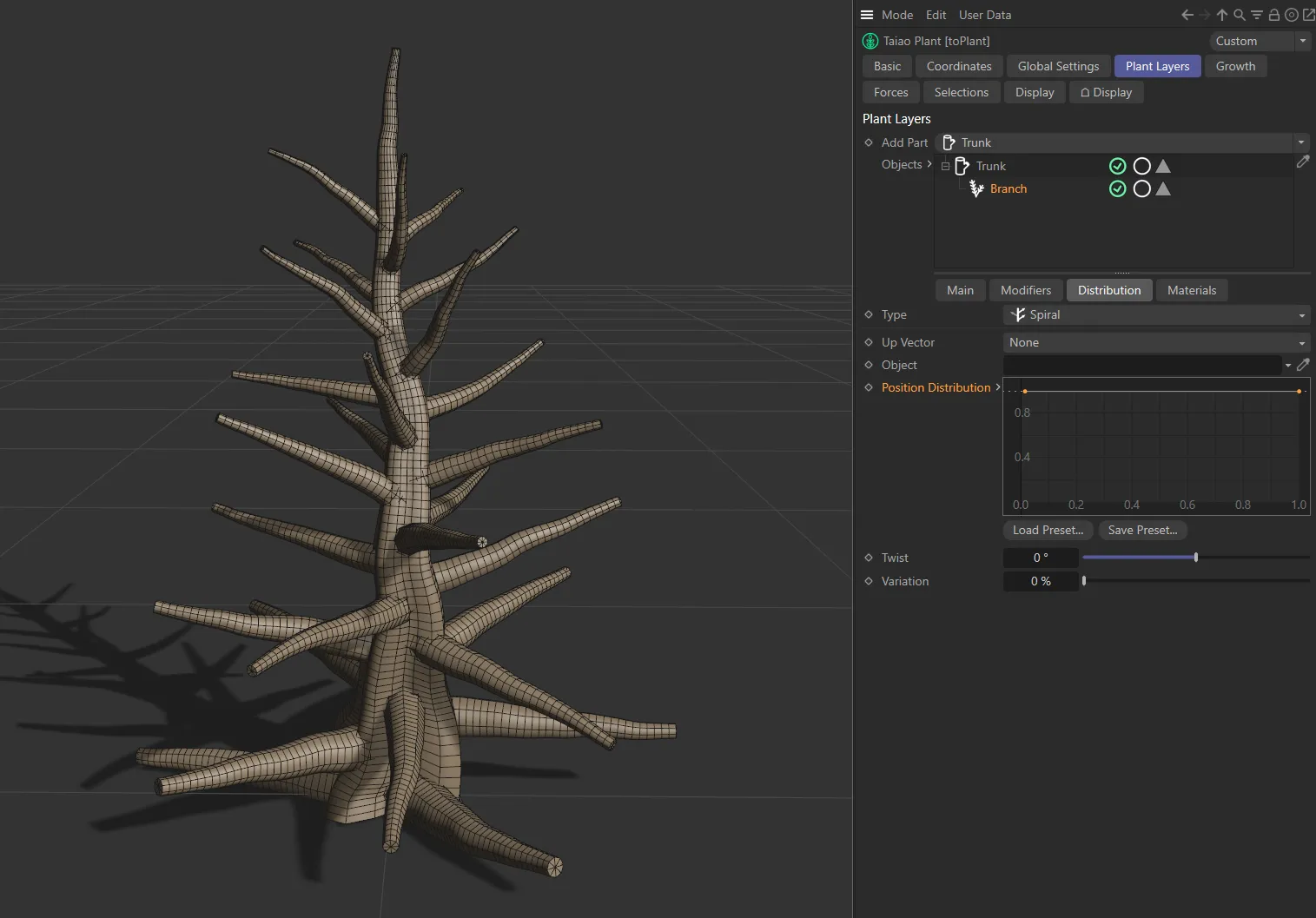
The Position Distribution spline curve is driving this image, with branches generated along the entire length of the trunk.
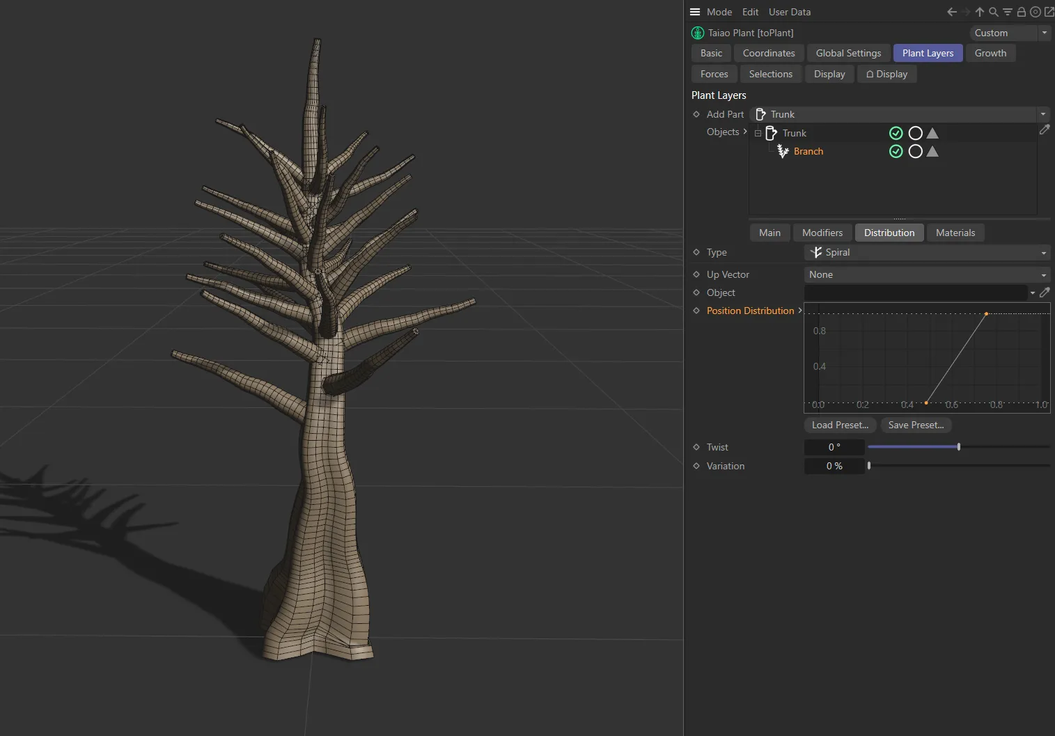
The linear increase beginning part-way along the X-axis means that branches are only generated from there.
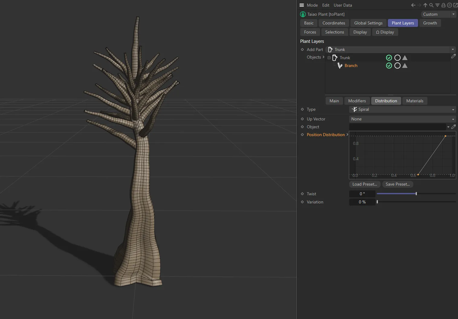
This spline curve is at 0 (zero) until 80% of the way along the X-axis, with a linear increase to the full amount of branches at the near top of the tree, creating a palm-tree style plant.
Distribution Variation
Section titled “Distribution Variation”Will apply a variation to the distribution of the branches, moving them up the Trunk layer as the percentage slider is higher.
This will twist the branches around the parent layer.
Animation to show the effect of the Twist slider.
Variation
Section titled “Variation”Varies the amount of twist around the parent layer.
Animation to demonstrate the effect of the Variation slider on the branch distribution.
Materials tab
Section titled “Materials tab”The Branch layer settings operate in exactly the same manner as described in the Trunk layer page.
Materials
Section titled “Materials”Simply drag your material into the Materials list and the branches will be textured using the material.
Here the material has been dragged and dropped into the Materials link field and is only affecting the Branch layer.
It is worth noting that the green tick icon to the right of the material can be clicked to turn it, and therefore the material texture, off.
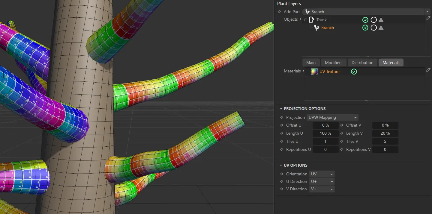
Projection, UV and Phong Options
Section titled “Projection, UV and Phong Options”These options operate in exactly the same way as described in the Trunk layer page.
Additional Branch Layers
Section titled “Additional Branch Layers”As this is a procedural layering system, you can, of course, add additional (sub) branch layers by ensuring the Branch layer is highlighted in the Add Part drop-down menu and select Branch from the menu.
This will add branches to your first Branch layer.
To add a further layers, highlight the branch layer that you wish to add a sub-layer to, click Add Part and select Branch once more.
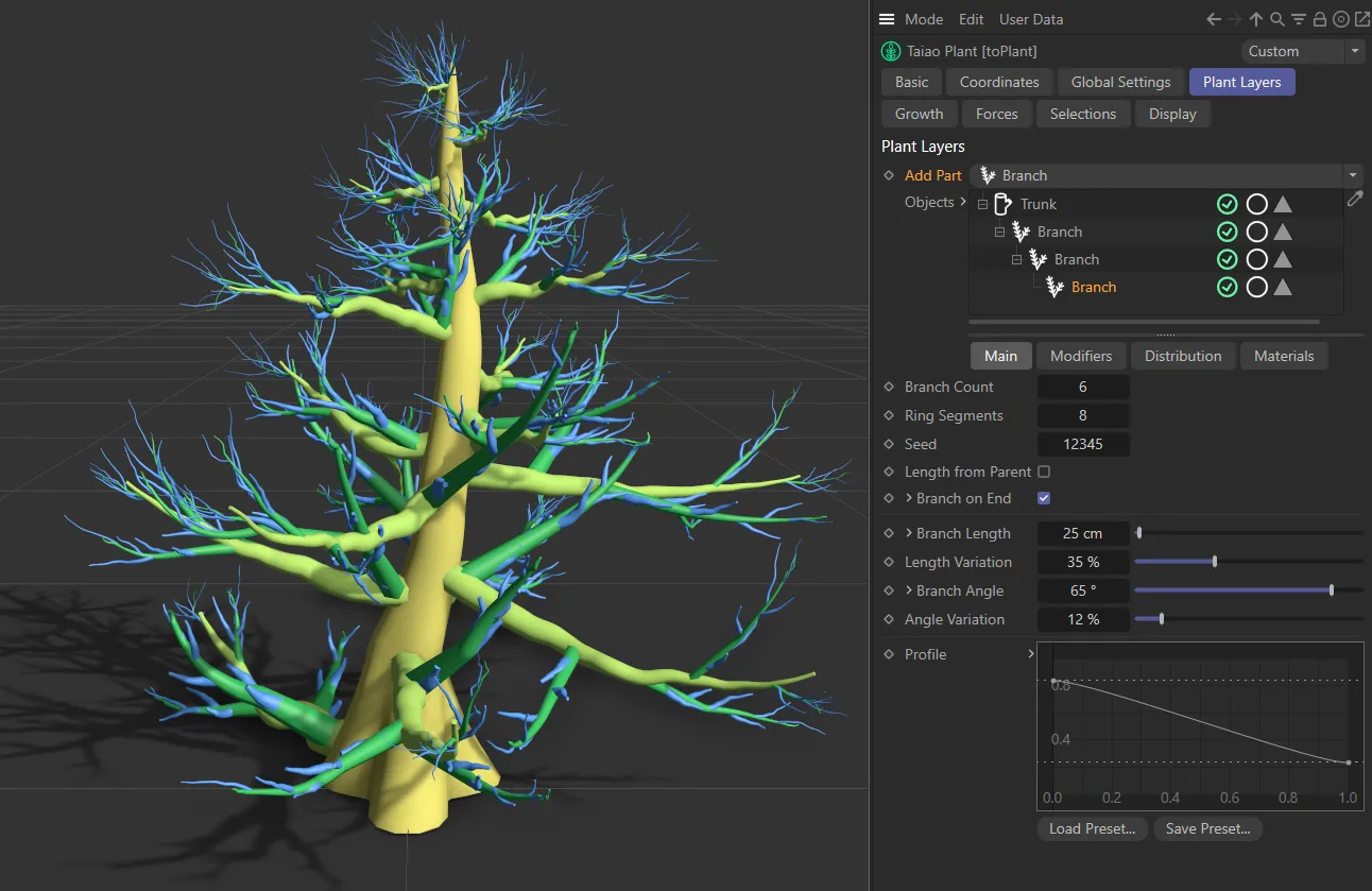
In this image, there are several sub-branch layers active. The first Branch layer has a yellow material attached here, while the second sub-layer branch has a green material and the third sub-layer branch has a blue material.
Copyright © 2026 INSYDIUM LTD. All rights reserved.