Koch
Overview Video
Section titled “Overview Video”Koch Options
Section titled “Koch Options”This mode uses the Koch Snowflake fractal technique to generate infinitely divisible triangle patterns.
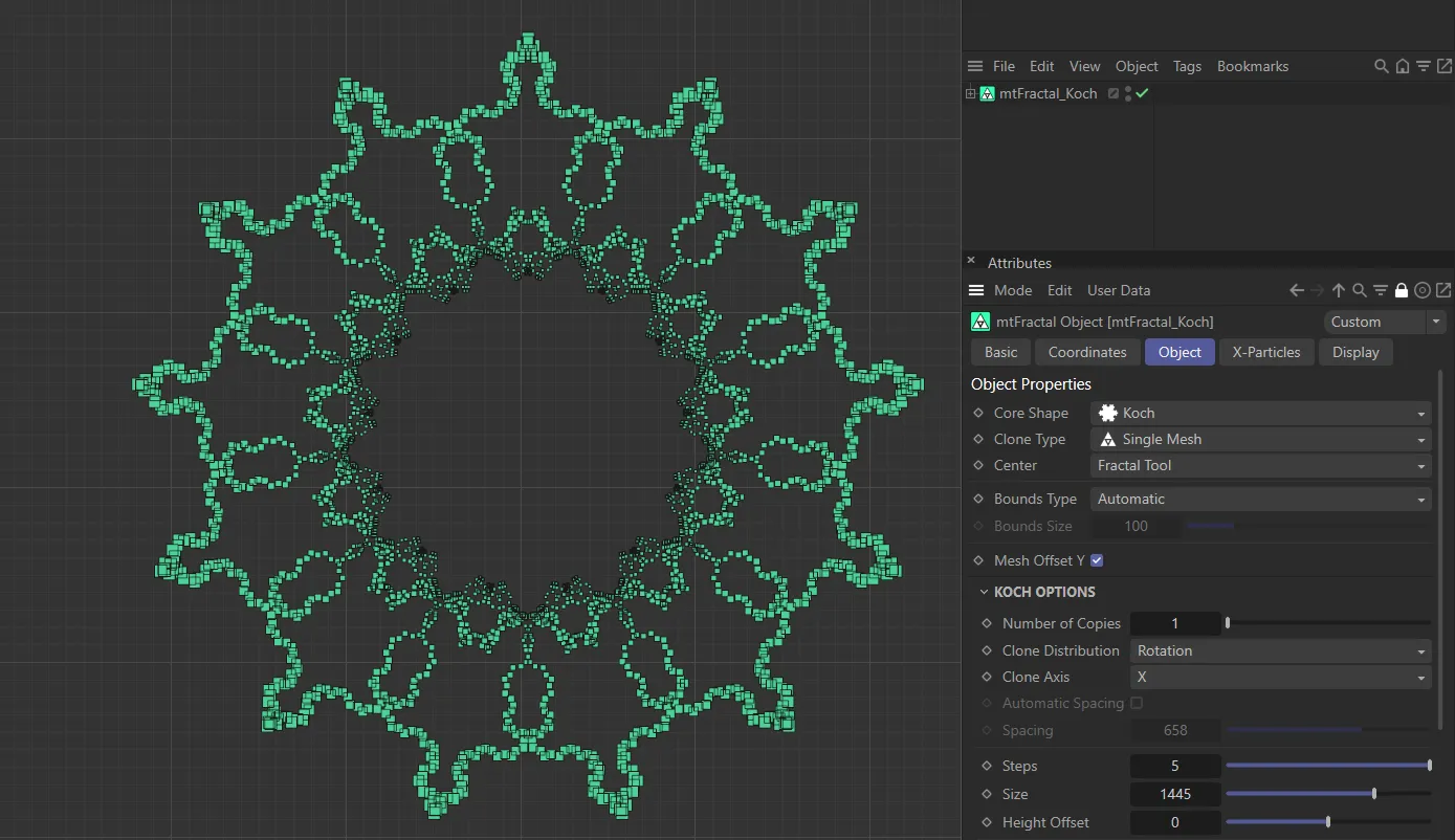
mtFractal Core Shape set as Koch.
Number of Copies
Section titled “Number of Copies”This option will duplicate the resulting fractal Koch shape in the axis set by the Clone Axis parameter.
Animation to demonstrate the increase in the Number of Copies value.
Clone Distribution
Section titled “Clone Distribution”Set as Rotation, by default.
The alternative setting is Tangent.
Rotation mode
Section titled “Rotation mode”From a point centered on the fractal shape, each cloned line is rotated equally around the axis chosen in Clone Axis.
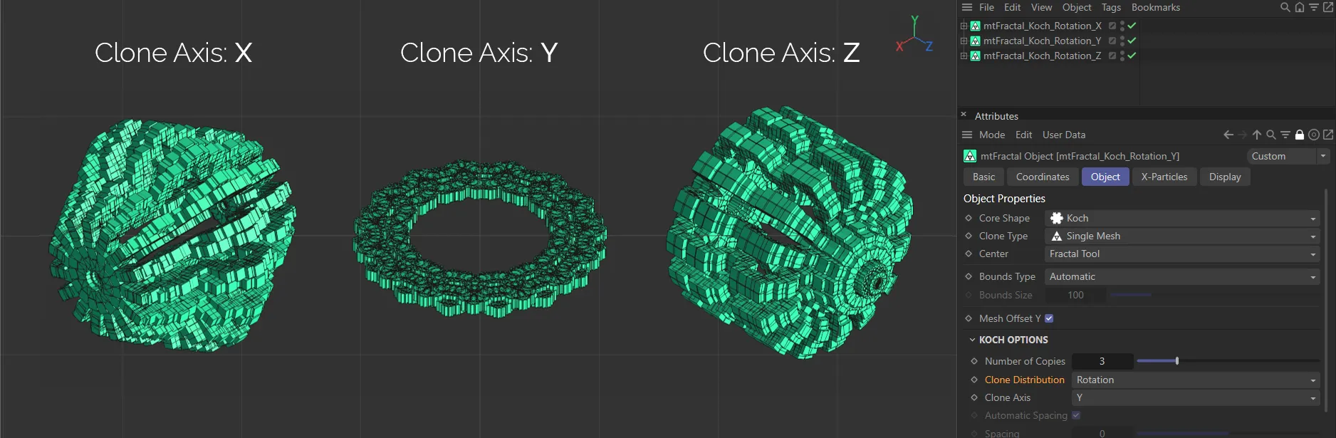
In this image, there are three examples of the Rotation mode of Clone Distribution, each with Number of Copies is set at 15. The Clone Axis is set as X on the left*, Y* in the center and Z on the right.
Tangent mode
Section titled “Tangent mode”Each clone is shifted along the chosen axis, by an automatic or manually chosen distance.
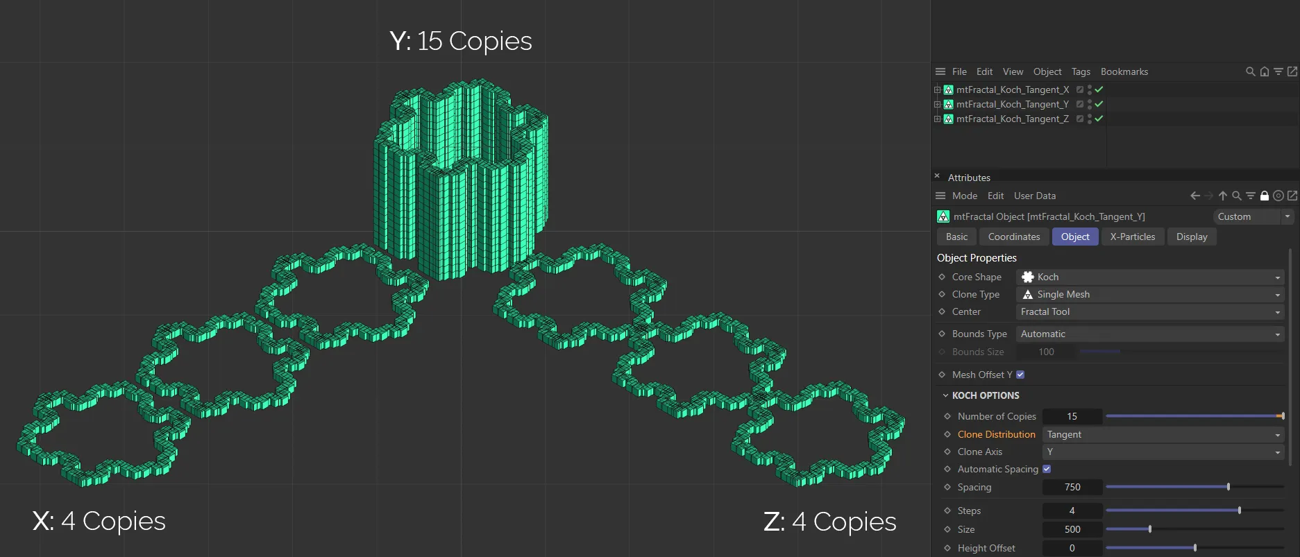
In this image, there are three examples of the Tangent mode of Clone Distribution. On the left, Number of Copies is set at 4, with the Clone Axis set as X. In the center, the Clone Axis is set as Y with a Number of Copies value of 15. On the right, the Number of Copies is 4, with the Clone Axis set as Z.
Clone Axis
Section titled “Clone Axis”The clone can be set on any axis, which you can select here.
It is set on the Y-axis by default.
Automatic Spacing
Section titled “Automatic Spacing”Enabled, by default, this calculates a bounding box of the source geometry, based on the Object Properties size settings for the object.
The copies are then automatically spaced apart by this bounding box distance.
Spacing
Section titled “Spacing”With Automatic Spacing disabled, this slider controls the spacing of the copies.
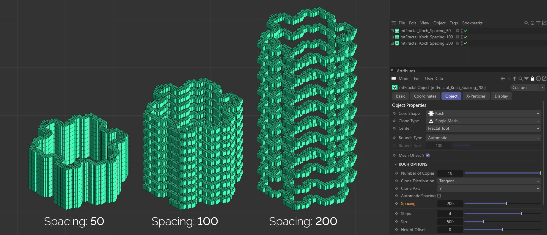
Here Automatic Spacing is disabled and the Spacing settings are 50, on the right, raised to 100, in the center, and 200, on the right.
For each step, Koch will subdivide a line into four smaller lines (the length of which is determined by the Size value), producing a triangle shape in the center.
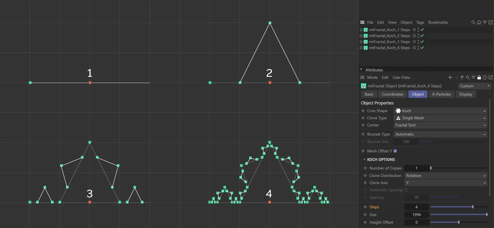
This image demonstrates the way that the Koch mode increases in detail, using the Steps setting. The red square is used as a visual aid, to show the center of the tool, from where the triangle shapes are generated. The Steps setting increases from 1 (in the top left), to 4 (in the bottom right).
The overall length of the very first line.
Height Offset
Section titled “Height Offset”A value which will shift the clones in the Y-axis, with clones further along the line being affected to a higher amount.
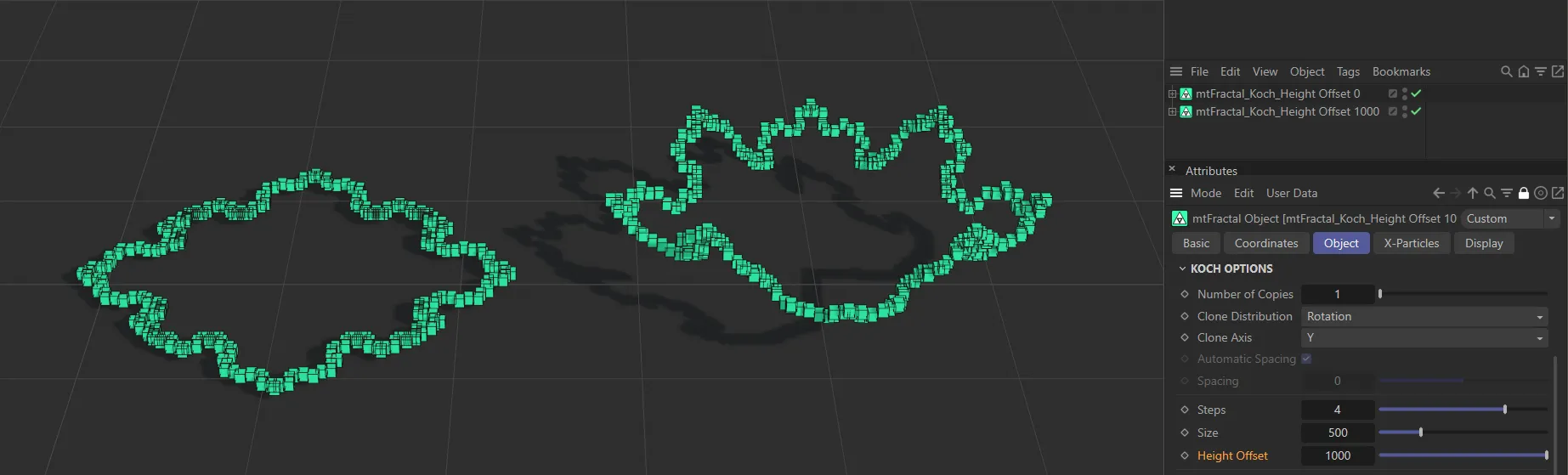
This image demonstrates the use of the Height Offset parameter, which is raised to 1000 on the right.
The number of starting lines in the shape.
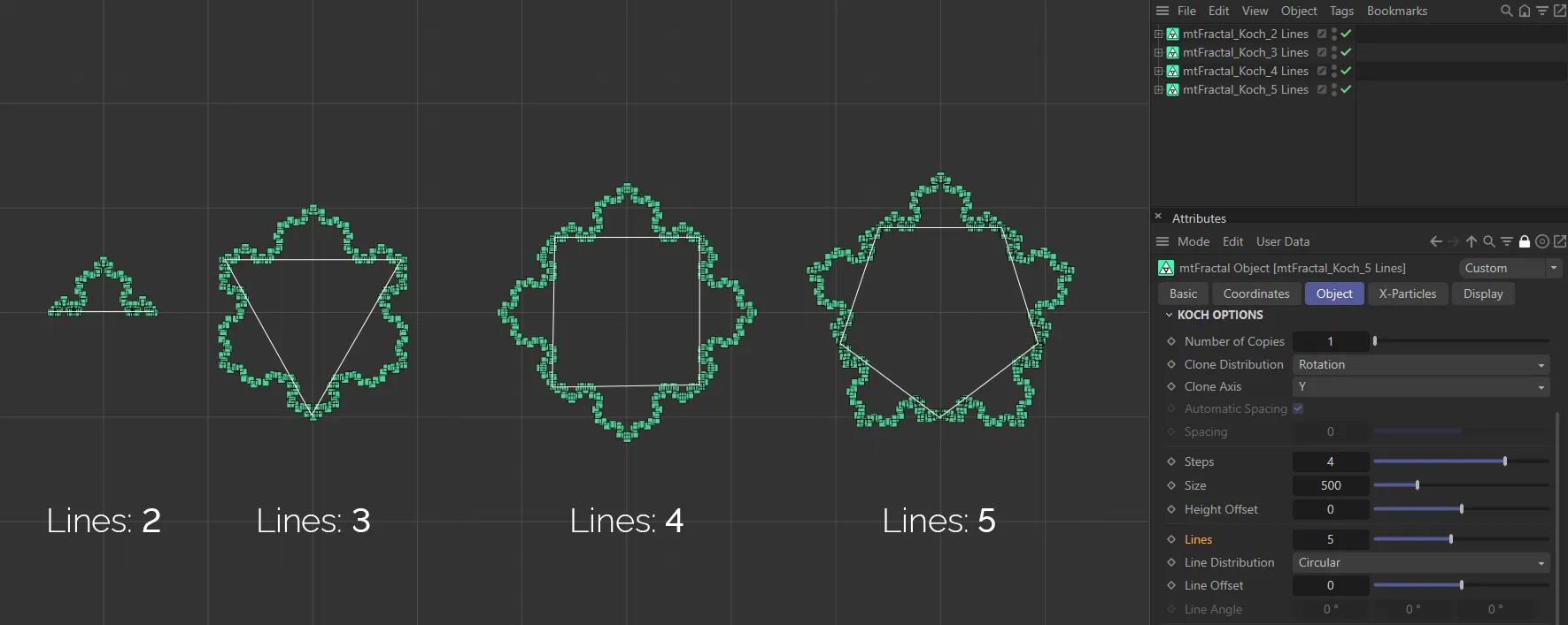
This image clearly demonstrates the Lines parameter, with values from 2 to 5, respectively. The 2D white-line shapes are there as a visual aid.
Line Distribution
Section titled “Line Distribution”Set at Circular, by default, options that dictate how each cloned line is transformed.
The other option is Angle.
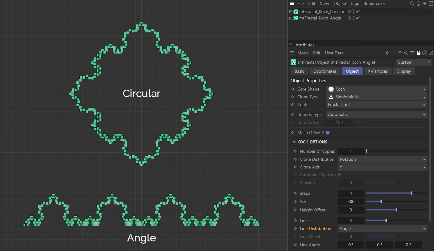
Examples of the Line Distribution settings of Circular and Angle.
Circular mode
Section titled “Circular mode”Each cloned line will be placed on the periphery of a circle.
Line Offset will adjust the radial distance.
Angle mode
Section titled “Angle mode”Each cloned line will be placed at a tangent, then consecutively rotated by the Line Angle setting.
Line Offset
Section titled “Line Offset”Only available in the Line Distribution setting of Circular, this slider setting offsets the individual lines from each other.
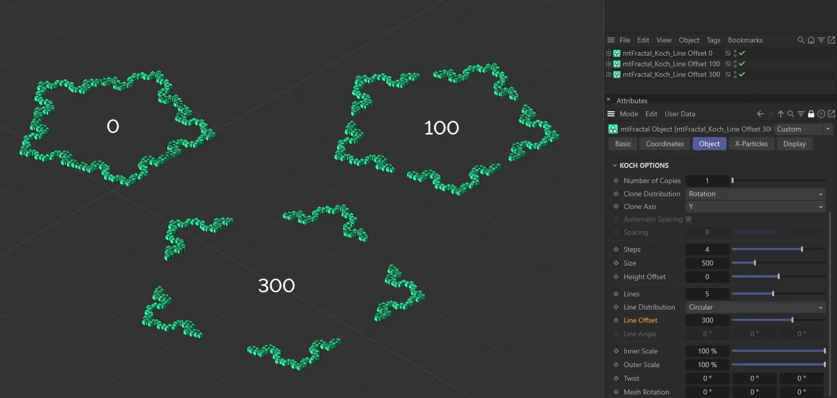
This image demonstrates the use of the Line Offset slider, with settings of 0 (zero), 100 and 300 showing the increase in the offset.
Line Angle
Section titled “Line Angle”Only available in the Line Distribution setting of Angle, these settings will bend or twist the lines in the different axes.
Animation to show the effect of the Line Angle sliders in each axis.
Inner Scale/Outer Scale
Section titled “Inner Scale/Outer Scale”Clones will be scaled by these different strength settings, depending on the position.
This angle will adjust the subsequent subdivided lines.
Animation to demonstrate the Twist setting in each of the three axes.
Mesh Rotation
Section titled “Mesh Rotation”This angle will adjust the clones only, not the position or direction of any line.
Levels & Nodes
Section titled “Levels & Nodes”The above steps all affect the fractal shape globally.
In order to apply targeted adjustments to an individual step of the shape, you can work with the Level Nodes controls.
Add Level
Section titled “Add Level”Clicking this button will add a level in the Levels link field.
Highlighting this level will give further Node Options parameters.
These additional features give the increased, detailed control over each individual step of the fractal shape, bypassing the global settings from the Object tab.
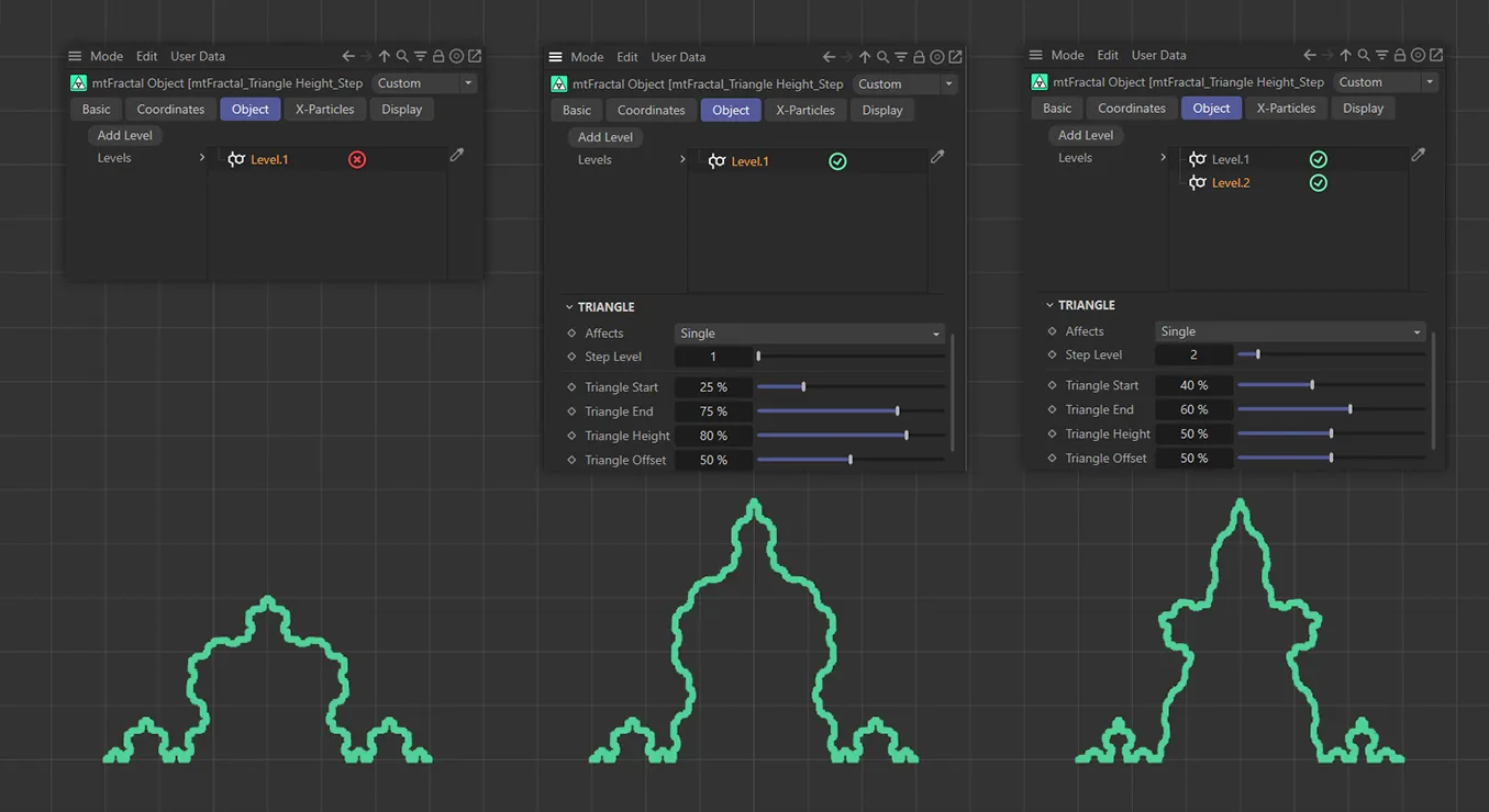
In the left-hand image, the additional Level.1 level is disabled, leaving all steps to be controlled by the global settings. The Step Level 1 is being driven by the Level.1 level in the fractal in the center, with an Triangle Start, End, Height and Offset settings seen above. In the right-hand image, Step Level 2 is being controlled by Level.2, with a different fractal shape being the result.
Affects
Section titled “Affects”When adding a level, the user can choose which step the other options in the node affect.
Set as Single, by default.
The other options are: Odd, Even, Range and Multiple Of.
Animation to demonstrate the effect of the Triangle Height slider on Step Level 1 (left-hand image) and Step Level 2 (right-hand image).
Single
Section titled “Single”By specifying the number in the Step Level slider, this node will only affect the Type setting choice of Angle or Branch at this step.
Odd/Even
Section titled “Odd/Even”Alternating steps are affected.
Similar to Single, the user specifies a Range Start and Range End of steps to affect, in the additional parameters available.
Multiple Of
Section titled “Multiple Of”By specifying the number in the Multiple Of slider, this node will only affect the Type setting choice of Angle or Branch at this step.
Step Level
Section titled “Step Level”This specifies the step of the fractal which you wish to change.
Triangle Start
Section titled “Triangle Start”Adjusts where the triangle starts on the step which you have specified.
Triangle End
Section titled “Triangle End”Adjusts where the triangle ends on the step which you have specified.
Triangle Height
Section titled “Triangle Height”Adjusts the height of the triangle on the step which you have specified.
Triangle Offset
Section titled “Triangle Offset”Offsets the triangle on the step which you have specified.
Copyright © 2026 INSYDIUM LTD. All rights reserved.