Global Settings
Overview Video
Section titled “Overview Video”mtFractal takes polygonal or spline child objects and distributes copies of these around geometric points of different fractal formulas.
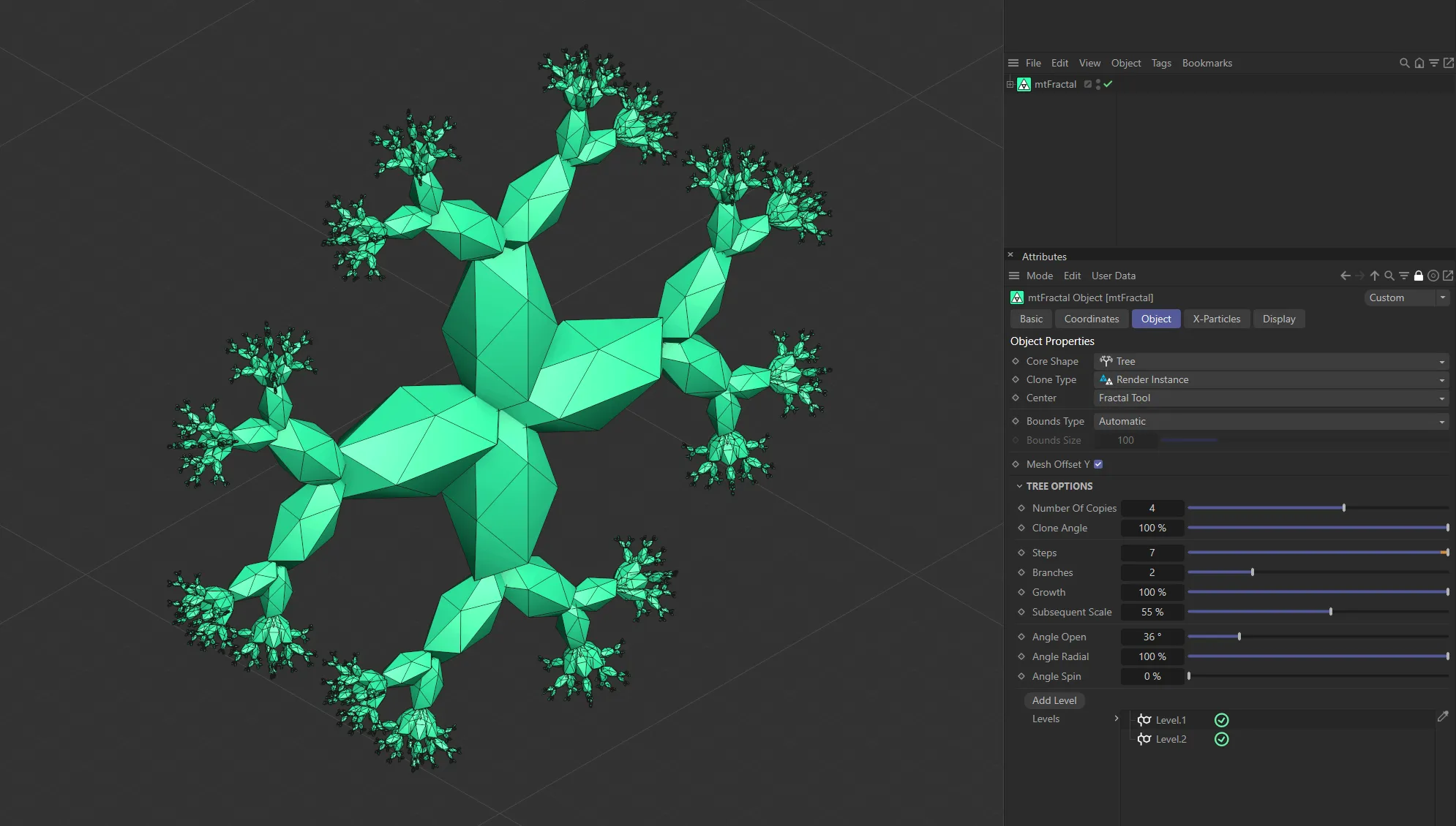
mtFractal with a Core Shape setting of Tree.
Object tab
Section titled “Object tab”Core Shape
Section titled “Core Shape”Set as Tree, by default.
The other options are: Dragon, Fern, Fibonacci, Koch and Sphere.
Each Core Shape option has its own specific option settings, which will change the parameters available.
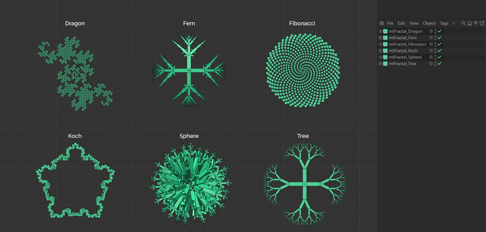
The six Core Shape modes of mtFractal.
For individual manuals, giving detailed instructions on each of these Core Shape modes, follow the linked pages below.
Dragon
The Dragon shape functions by duplicating all previous entries in the node (clone) list and rotating them around the end point.
Fern
The Fern shape shares similarities with the Tree shape but, due to the self-replicating manner, an increase in iterations can quickly produce a mass number of clones.
Fibonacci
This mode uses the Fibonacci number sequence to generate a curve, along which clones will be placed along at equal spacing.
Koch
This mode uses the Koch Snowflake fractal technique to generate infinitely divisible triangle patterns.
Sphere
This fractal shape focuses on different ways of distributing points around a center.
Tree
This shape repeats the clone out onto multiple branches, with options to change the angle and quantity.
Each clone is positioned at the top middle of the previous branch segment.
Clone Type
Section titled “Clone Type”Set as Render Instance, by default, this dictates the format that clones will be produced.
The alternative options are: Polygon, Single Mesh and Multi-Instance.
Polygon
Section titled “Polygon”Each clone is an individual polygon clone object.
Single Mesh
Section titled “Single Mesh”All clones are combined as geometry into a single polygon object.
Render Instance
Section titled “Render Instance”Produces a single parent object, with each clone being an instance of it.
Multi-Instance
Section titled “Multi-Instance”Produces a single parent object, with a single multi-instance object containing all clone data.
Center
Section titled “Center”Set as Fractal Tool, by default.
The other option is Mesh.
Fractal Tool
Section titled “Fractal Tool”The center of the resulting clones will be at the origin of the mtFractal object itself.
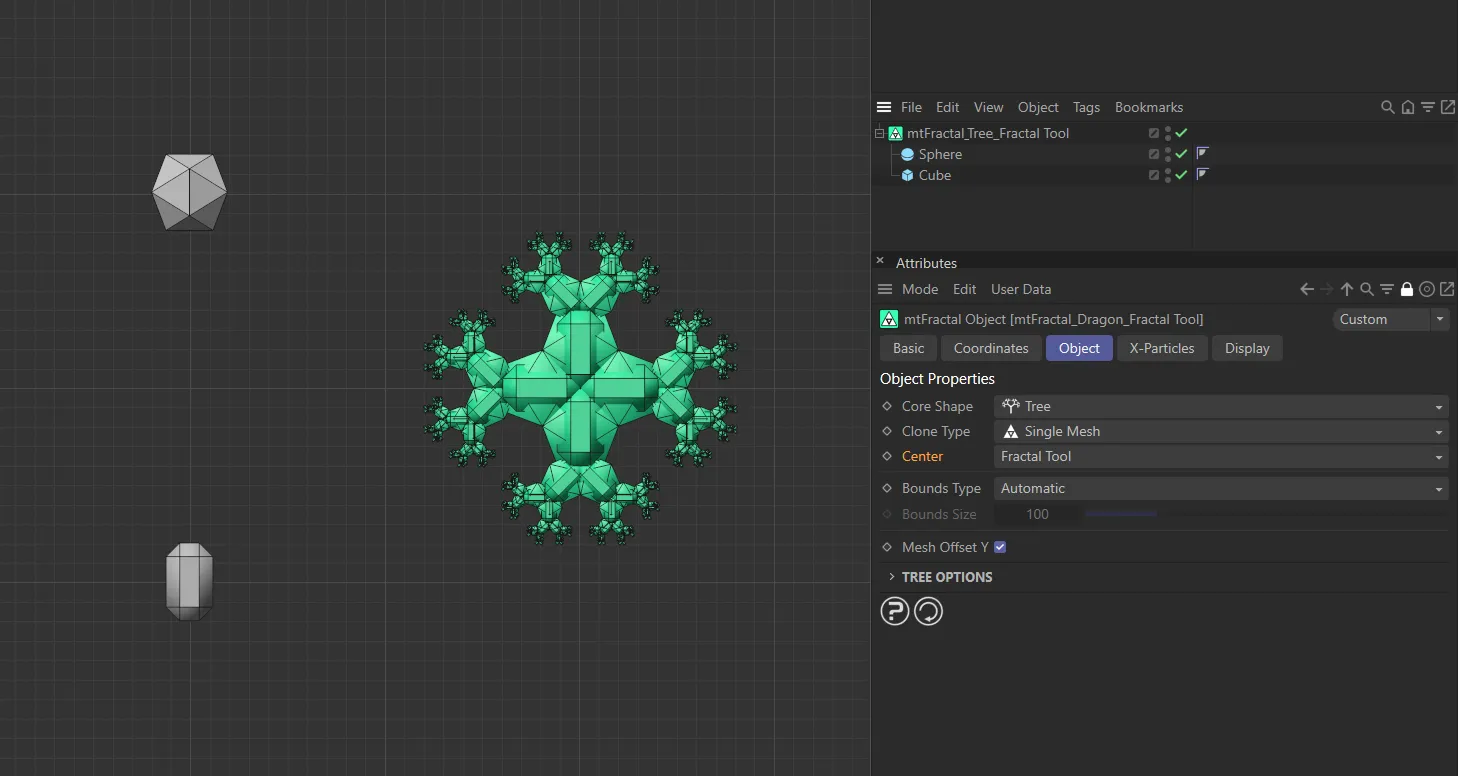
In this scene, with Center set as Fractal Tool, the two primitive objects are being combined to create a single fractal object.
Each fractal shape is created from the child polygon object.
Making multiple polygon objects children of mtFractal will result in multiple individual fractal shapes.
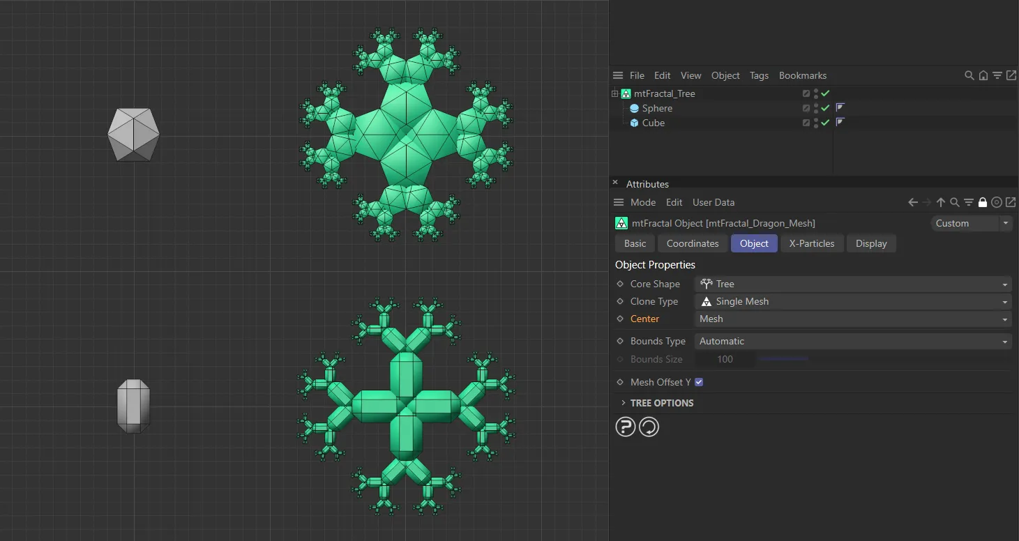
With Center mode set as Mesh, mtFractal is generating two separate fractals, both respecting the geometry and position of the two input objects.
Bounds Type
Section titled “Bounds Type”There are two types: Automatic and Fixed.
Automatic
Section titled “Automatic”The box’s own radius will be used as the Y-height of the bounding box.
The highest point on the Y-axis of the polygon object will be used as the point from where the clones originate.
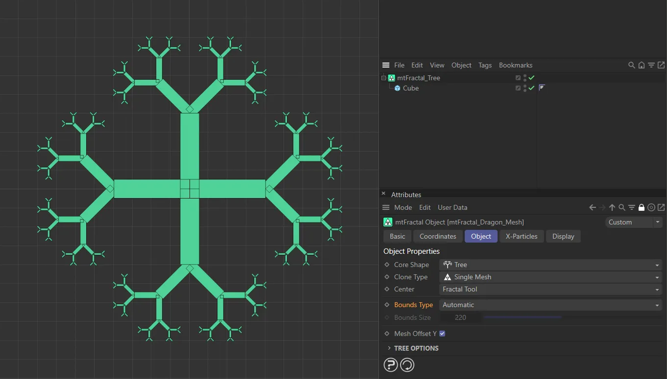
In this image, with the Bounds Type set at Automatic, the Cube has a Y-height of 200cm, which is being used to generate the bounding box.
You can set your own Y-height, using the Bounds Size setting.
The Bounds Size value will be the point from where the clones originate.
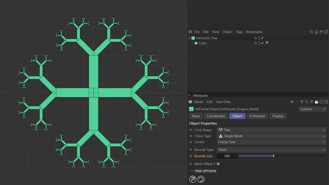
In this image, the Bounds Size value is raised to 200, with the Bounds Type still in Fixed and this gives the same result as when the Bounds Type is set to Automatic because the Cube has a Y-height of 200cm.
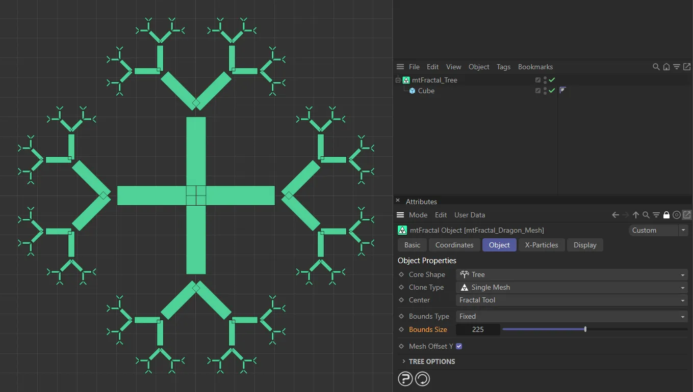
Now the Bounds Size value has been raised further, to 225, offsetting the fractal by 25cm.
Bounds Size
Section titled “Bounds Size”Use this parameter to set the Y-height of the bounding box.
Mesh Offset Y
Section titled “Mesh Offset Y”Enabled by default, this offsets the mesh in the Y-axis, based on clones being created from the lowest point of the Y-axis.
Disabling this setting will use this same point of the Y-axis, but this time clones will be created from the center of the object.
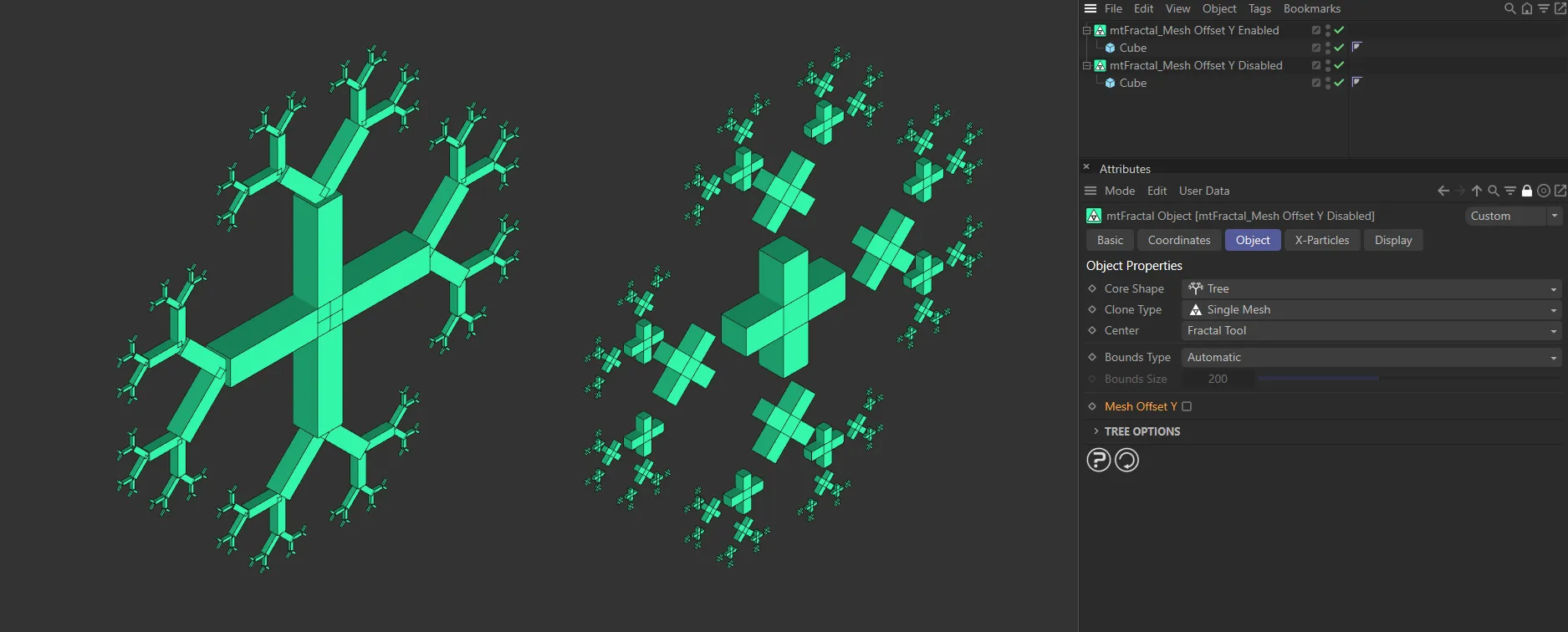
Mesh Offset Y, enabled on the left, offsets the child Cube on the Y-axis. Disabled on the right, this generates copies from the center of the mesh.
X-Particles tab
Section titled “X-Particles tab”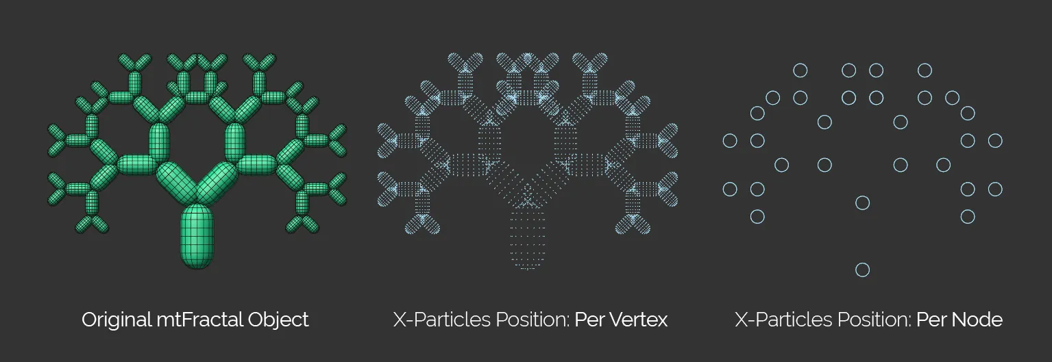
This image first shows the mtFractal object, then the resulting two Position settings: the Per Vertex and the Per Node.
Emitter
Section titled “Emitter”Drag and drop a scene emitter into this field, to utilize its settings.
Add Emitter
Section titled “Add Emitter”Click this button to add a new scene emitter and automatically set it up as a controlled emitter.
Position
Section titled “Position”Set as Per Node, by default.
The other option is Per Vertex.
Per Node
Section titled “Per Node”Generates a particle for each node/clone of the object.
Per Vertex
Section titled “Per Vertex”Generates a particle for each vertex in the cloned objects.
Particles Inherit Scale
Section titled “Particles Inherit Scale”Enabled by default, the particles follow the Subsequent Scale value in the individual options settings, to determine their size (dependent on emitter Display settings).
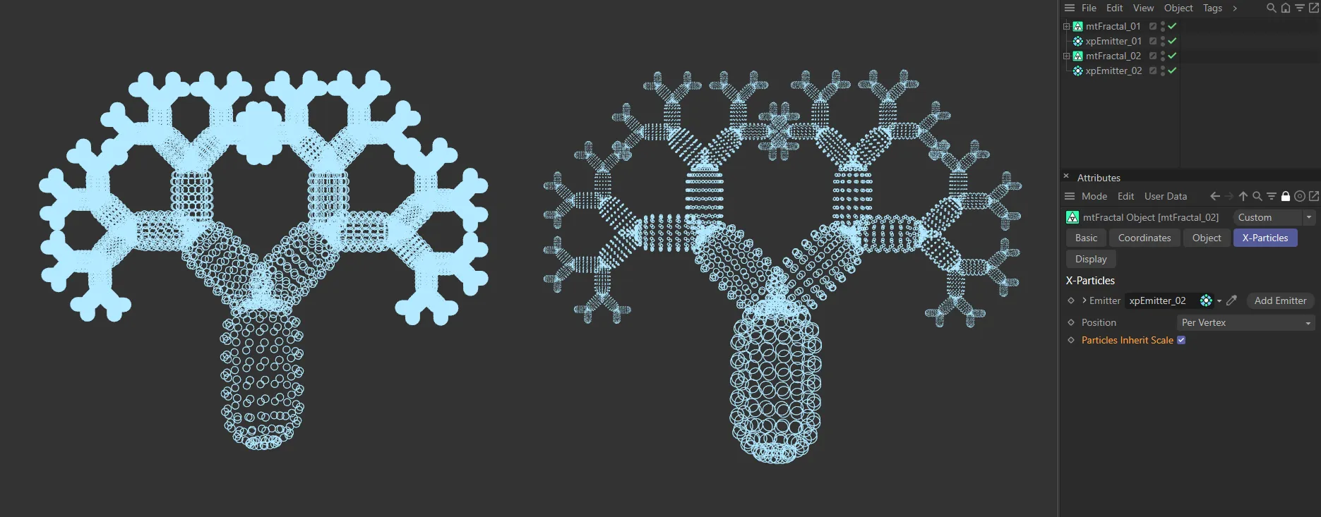
Here, Particles Inherit Scale is disabled in the first image, then enabled in the second.
Display tab
Section titled “Display tab”Set at Mesh, by default.
The alternatives are: Box Shaded, Box, Dot, Spline and Hide All.
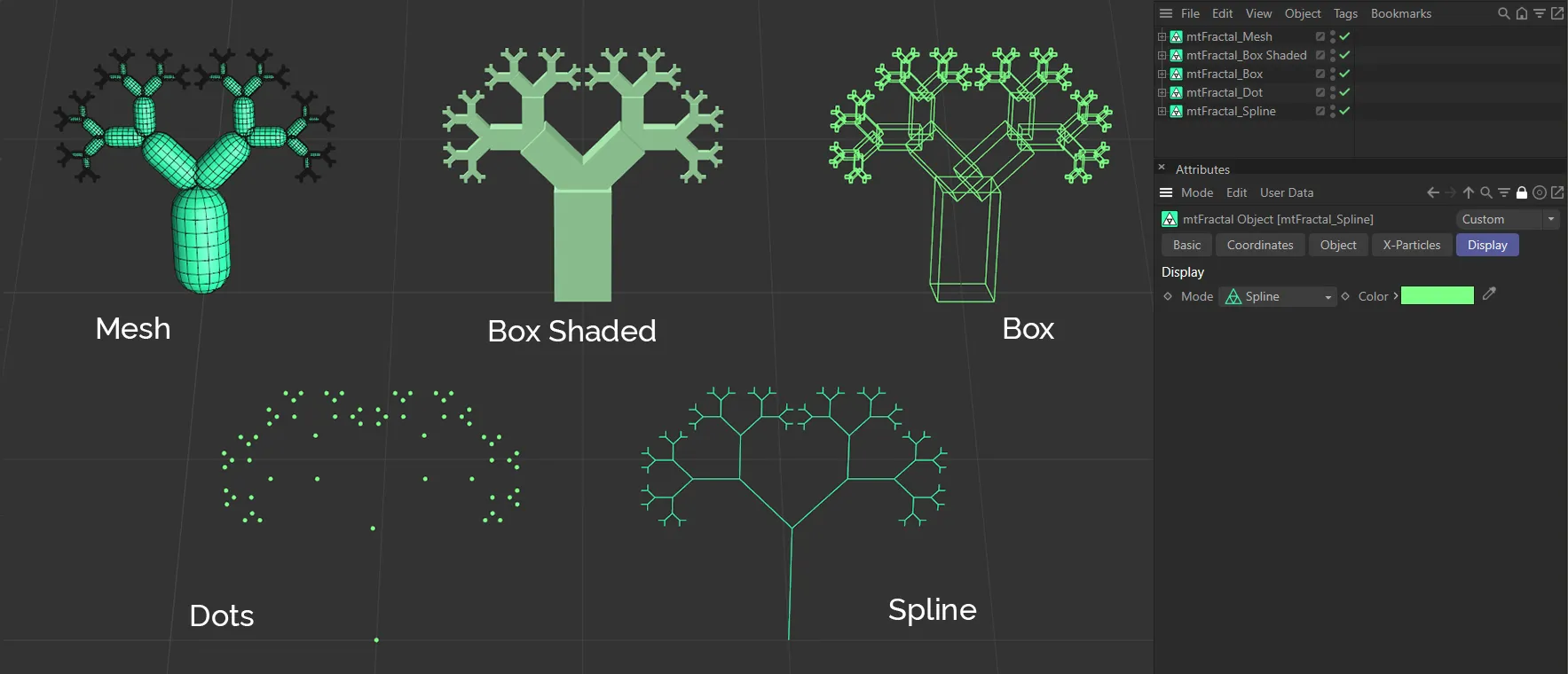
This image shows the five different Mode settings: Mesh, Box Shaded, Box, Dots and Spline.
Mesh mode
Section titled “Mesh mode”This mode allows you to see copies of your original object in your scene.
Box Shaded mode
Section titled “Box Shaded mode”A much better viewport-efficient way of viewing your clones, with them all being ‘boxed in’, in the manner of Minecraft.
Box mode
Section titled “Box mode”This mode displays box outlines of the clone shapes.
Dot mode
Section titled “Dot mode”This mode replaces every clone with a single dot.
Spline mode
Section titled “Spline mode”Creates a simple spline model of the object.
Hide All mode
Section titled “Hide All mode”Removes the display entirely from the viewport.
With the Mode set as Box or Dot, this color picker can change the color from the default green setting.
Copyright © 2026 INSYDIUM LTD. All rights reserved.