Fibonacci
Overview Video
Section titled “Overview Video”Fibonacci Options
Section titled “Fibonacci Options”This mode uses the Fibonacci number sequence to generate a curve, along which clones will be placed along at equal spacing.
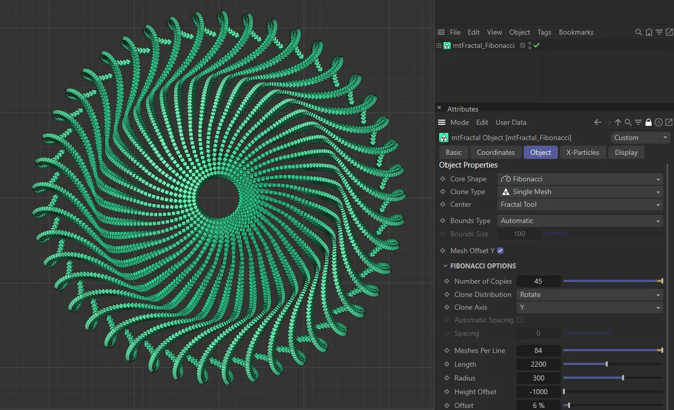
mtFractal Core Shape set as Fibonacci.
Number of Copies
Section titled “Number of Copies”This option will duplicate the resulting fractal Fibonacci shape in a rotation on the axis, determined by the Clone Axis setting.
Animation to demonstrate the increase in the Number of Copies value.
Clone Distribution
Section titled “Clone Distribution”Set as Rotate, by default.
The alternative setting is Tangent.
Rotate mode
Section titled “Rotate mode”From a point centered on the fractal shape, each cloned line is rotated equally around the axis chosen in Clone Axis.
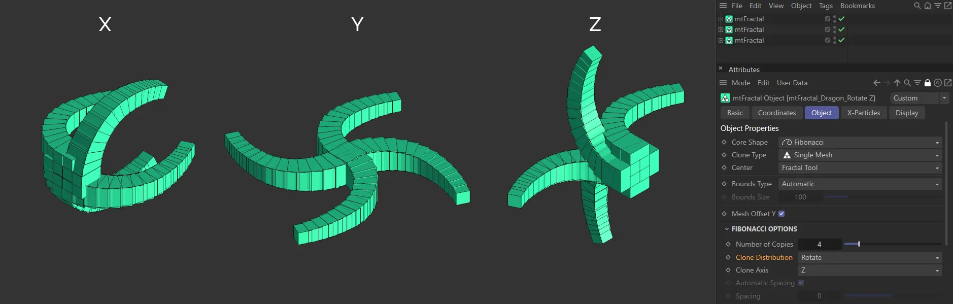
In the above image, with Clone Distribution set at Rotate, the settings for Clone Axis in X, Y and Z are shown.
Tangent mode
Section titled “Tangent mode”Each clone is shifted along the axis, by an automatic or manually chosen distance.
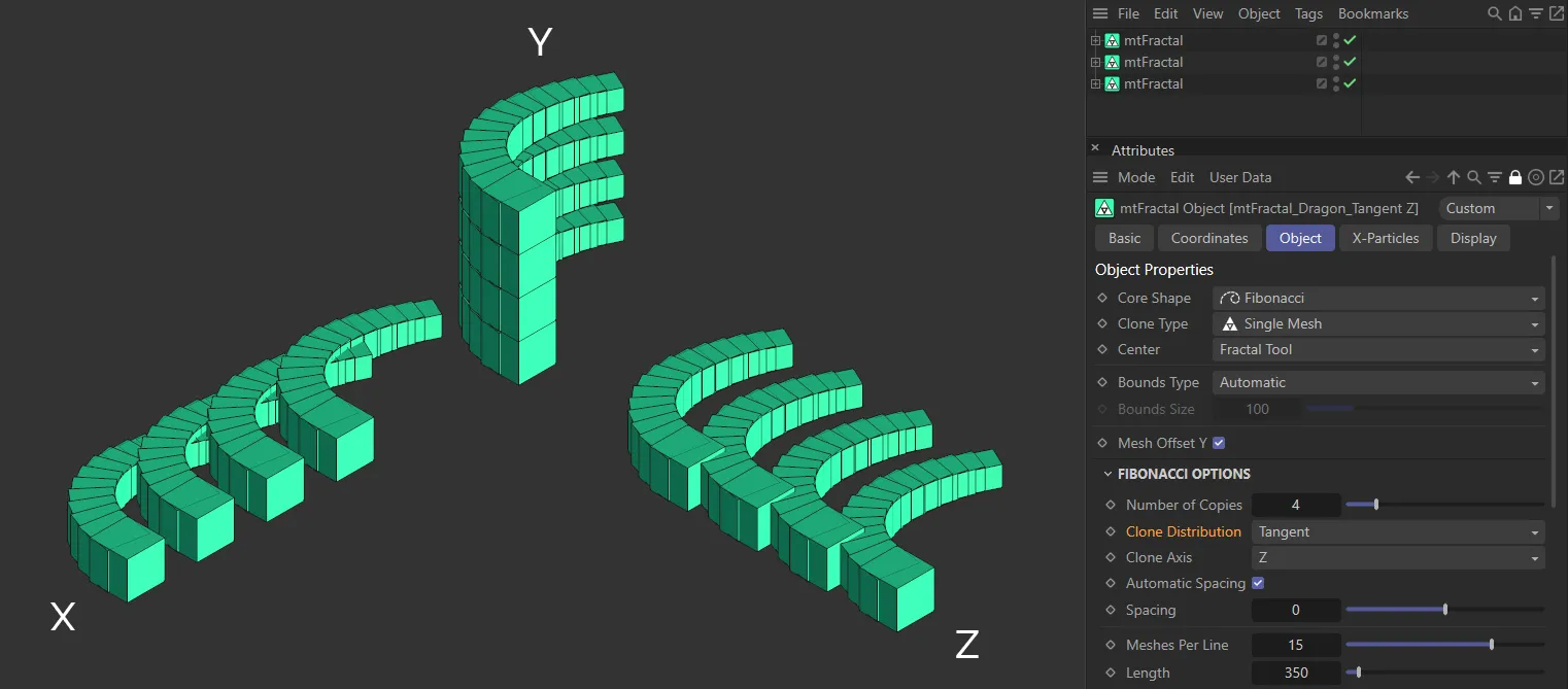
Here, with Clone Distribution in Tangent mode, again the settings for Clone Axis in X, Y and Z are displayed.
Clone Axis
Section titled “Clone Axis”The clone can be set on any axis, which you can select here.
It is set on the Y-axis by default.
Automatic Spacing
Section titled “Automatic Spacing”Enabled, by default, this calculates a bounding box of the source geometry, based on the Object Properties size settings for the object.
The copies are then automatically spaced apart by this bounding box distance.
Spacing
Section titled “Spacing”With Automatic Spacing disabled, this slider controls the spacing of the copies.
Meshes Per Line
Section titled “Meshes Per Line”The number of nodes (clones) generated along a single line of the chosen Length value.
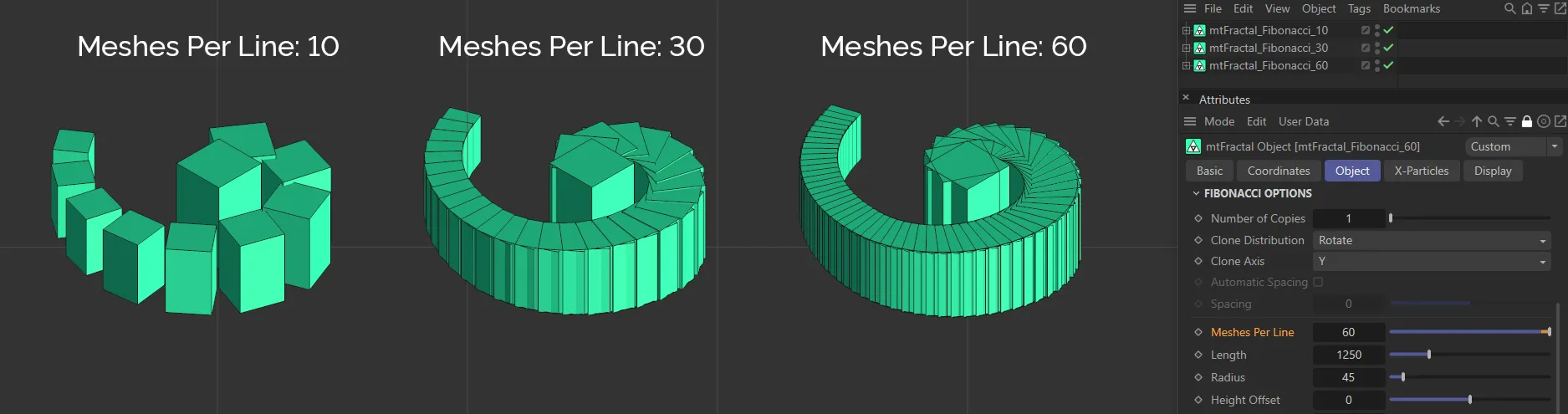
This image clearly demonstrates the Meshes Per Line parameter, with values of 10, 30 and 60 from left to right.
Length
Section titled “Length”Value set for the line length.
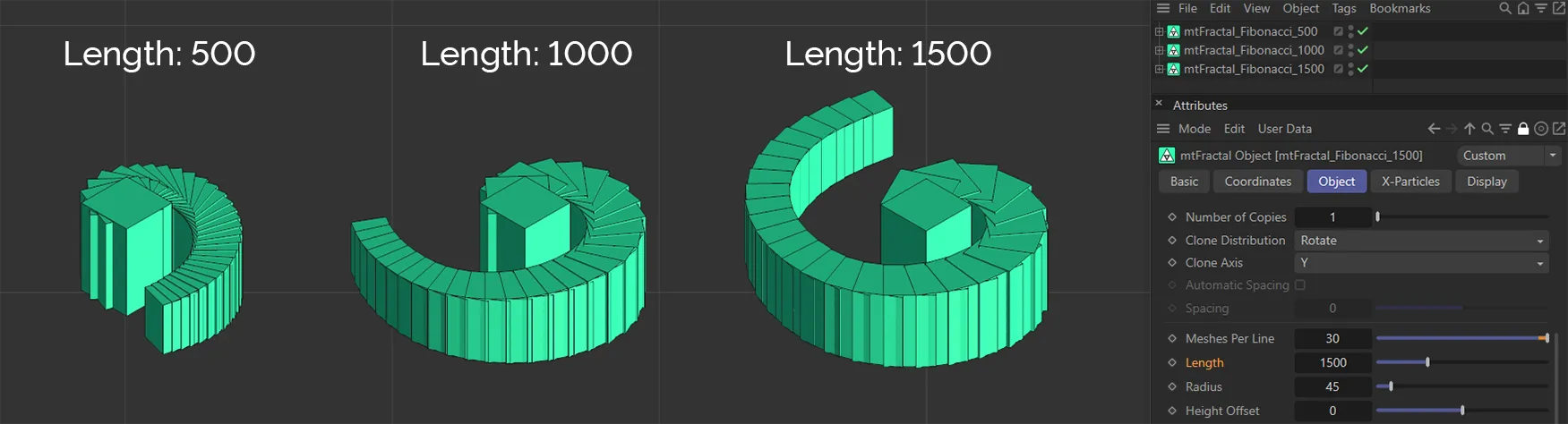
Above, the Length settings are 500, on the left, 1000 in the center and 1500, on the right.
Radius
Section titled “Radius”Adjusts the strength of the curve of the spiral.
Height Offset
Section titled “Height Offset”A value which will shift the clones in the Y-axis, with clones further along the line being affected to a higher amount.
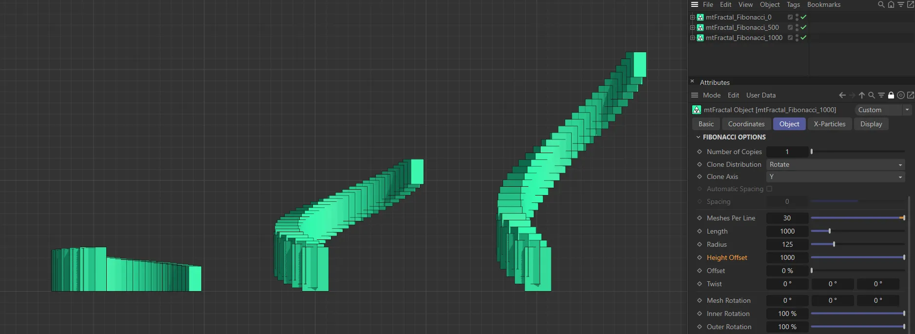
In this image, the Height Offset is 0 (zero) on the left, raised to 500 in the center and up to 1000 on the right.
Offset
Section titled “Offset”Moves the clones along the line, removing those that move past the end.
An angle that is applied to all the clones, contorting the line.
Mesh Rotation
Section titled “Mesh Rotation”Rotates the clone mesh along the different axes.
Inner Rotation/Outer Rotation
Section titled “Inner Rotation/Outer Rotation”These values adjust the strength of the Mesh Rotation, based on the step.
Inner Rotation will have a stronger effect on clones closer to the primary sphere, while Outer Rotation will have a stronger effect on the last clones in the tendril.
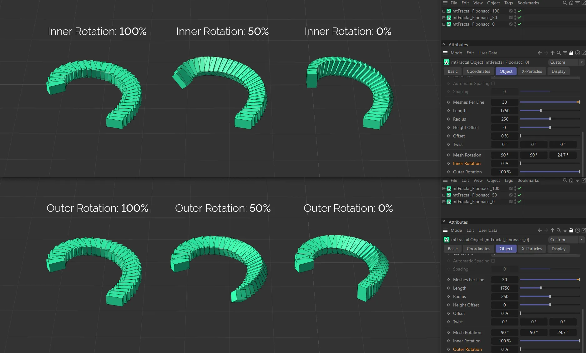
This image demonstrates the differences in the Inner Rotation and Outer Rotation parameters. In the three examples above, the Inner Rotation is set at 100% on the left, lowered to 50% in the center and at 0 (zero) % on the right. In the lower images, the Outer Rotation is set at 100% on the left, lowered to 50% in the center and, then again, at 0 (zero) % on the right.
Inner Scale/Outer Scale
Section titled “Inner Scale/Outer Scale”Scaling options that affect clones at the start and end of the line by a different strength.
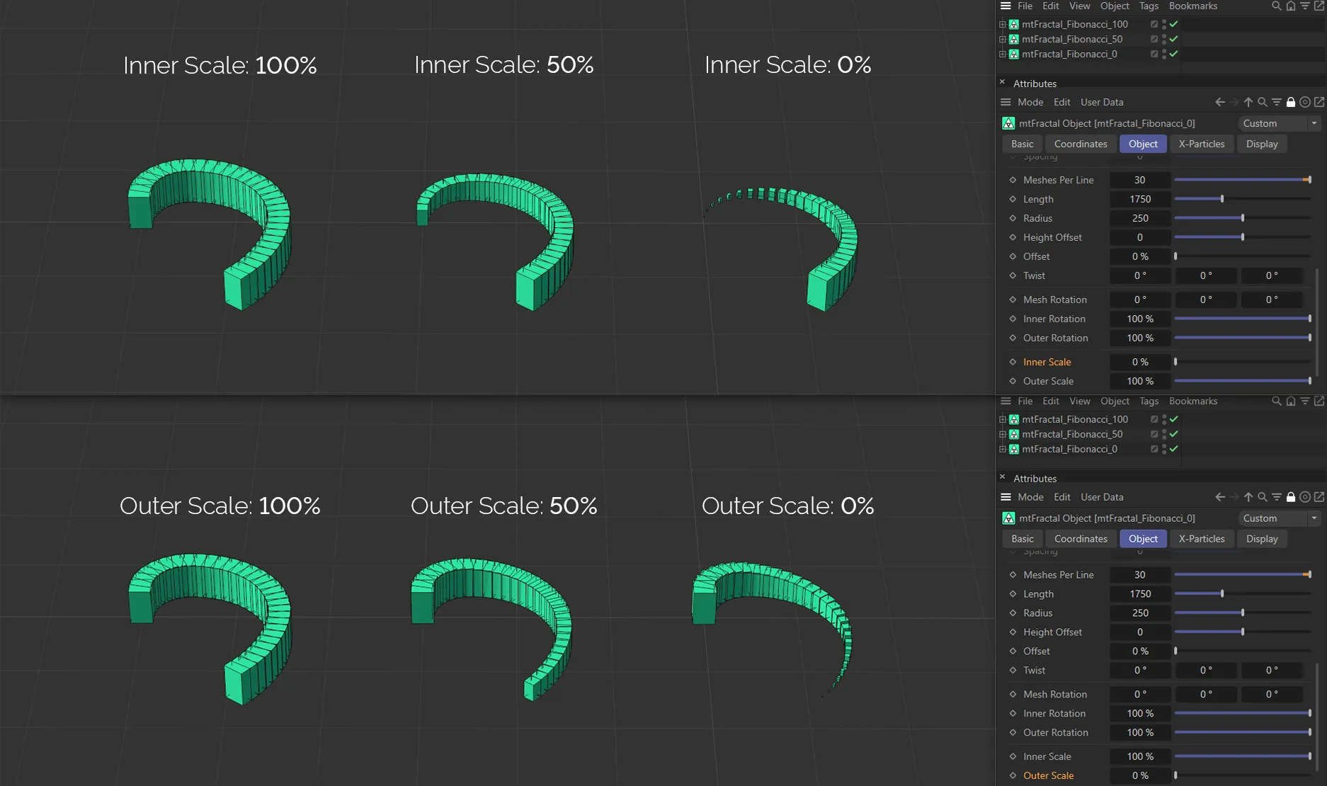
This image demonstrates the differences in the Inner Scale and Outer Scale parameters. In the three examples above, the Inner Scale is set at 100% on the left, lowered to 50% in the center and at 0 (zero) % on the right. In the lower images, the Outer Scale is set at 100% on the left, lowered to 50% in the center and then again at 0 (zero) % on the right.
Copyright © 2026 INSYDIUM LTD. All rights reserved.