jdFlowCam
jdFlowCam is a procedural tool for smoothly moving a camera between points and easily adjusting the timings of these points, whilst keeping a smooth path between them.
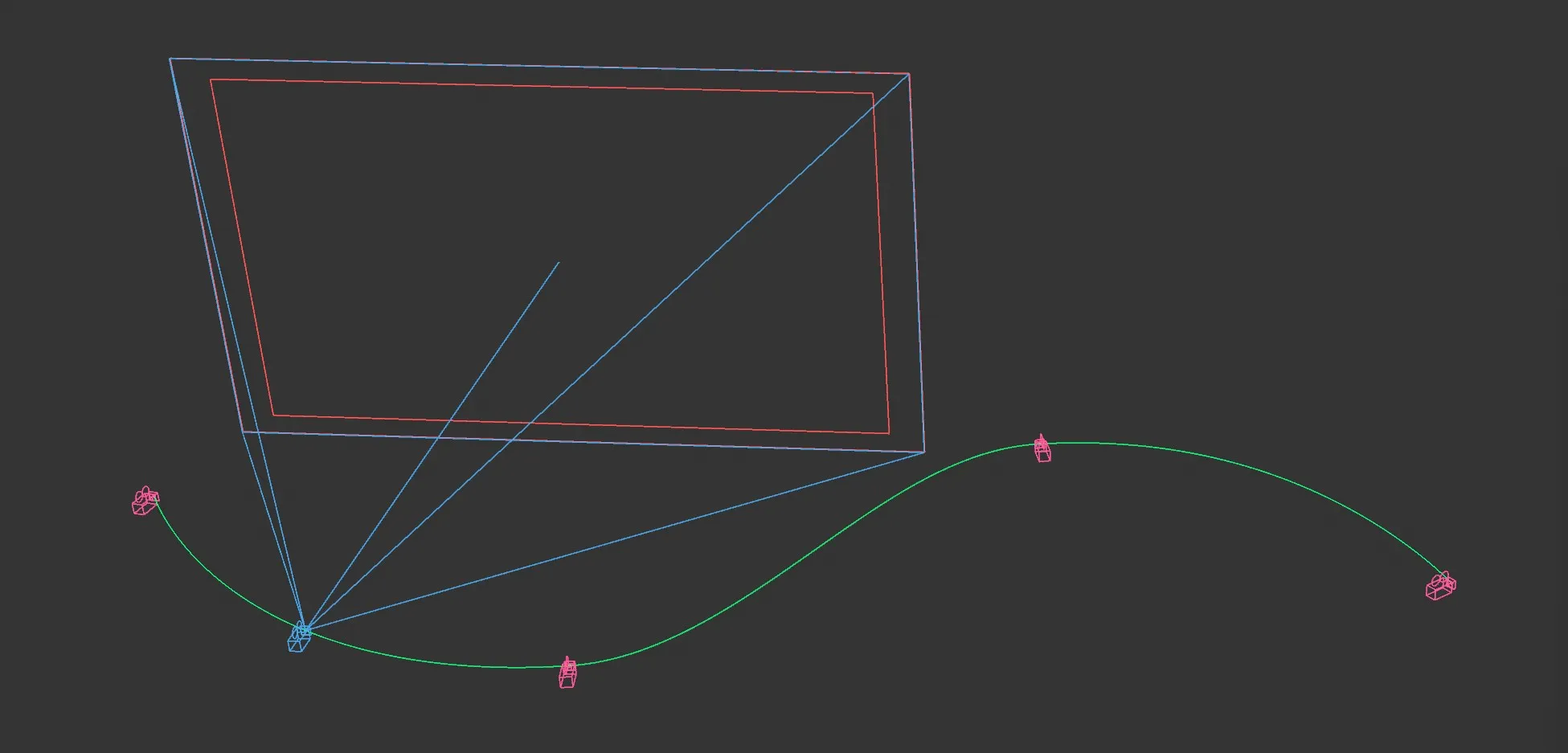
jdFlowCam, Viewport.
CamPoints are used by jdFlowCam to define the positions that the camera should pass through.
The user defines multiple CamPoints for jdFlowCam to smoothly move the camera between.
The CamPoints are distributed evenly along the timeline by a weight system (CamPoints with more weight will take up more time).
Object tab
Section titled “Object tab”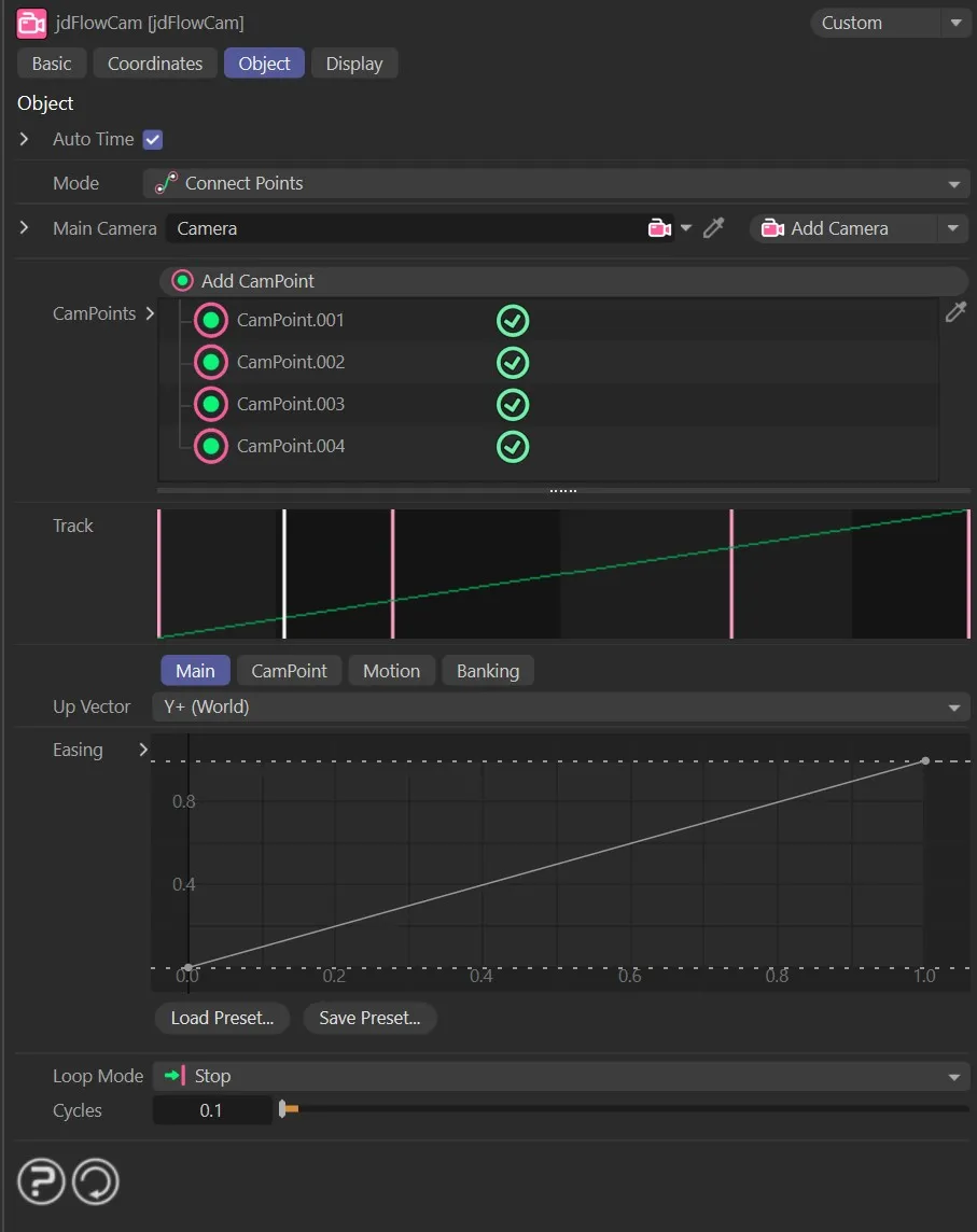
jdFlowCam, Object tab menu settings.
Auto Time
Section titled “Auto Time”Allows you to choose whether to automatically discern the start and end time from the project timeline.
When disabled, you can enter the times manually in the Start Time and End Time parameters, accessed via the drop-down arrow.
Start Time, End Time
Section titled “Start Time, End Time”Specifies a start and end time for the motion.
Set to Connect Points, by default, which uses the CamPoints to define the camera’s motion.
The alternative setting is Path, which uses a preset spline for the camera’s motion.
When Path is selected, a Path tab becomes available, with options to define how the camera uses the path (described below).
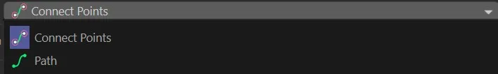
jdFlowCam, Mode menu settings.
Main Camera
Section titled “Main Camera”Drop a camera into this field to be the camera that jdFlowCam will move.
Add Camera
Section titled “Add Camera”Creates a new Camera object and adds it to the link box above.
Add CamPoint
Section titled “Add CamPoint”Creates a new CamPoint at the camera’s current position and adds it to the list.
CamPoints
Section titled “CamPoints”Here, the CamPoints in the list can be seen and selected to change their values.
The green check mark next to each CamPoint can be disabled to remove it from the Track interface.
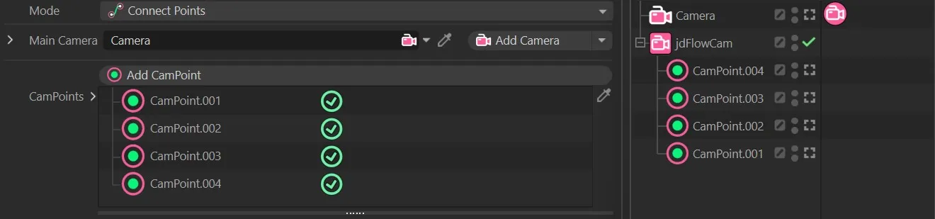
jdFlowCam, CamPoints list and Object Manager objects.
The Track interface lets the user slide CamPoints back and forth along the timeline by adjusting the weights of the surrounding CamPoints.
Pink lines – unselected CamPoints White line – current frame marker Green line – selected CamPoint Blue shaded area – Hold Time around a CamPoint.
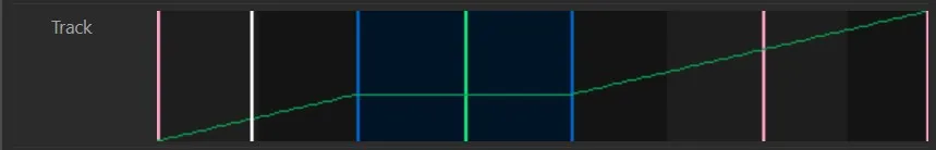
jdFlowCam, Track Display.
Main tab
Section titled “Main tab”The main settings that affect the overall behavior of the camera.
Up Vector
Section titled “Up Vector”Sets the up vector used in spline normal calculations (this can usually be left alone).
The default setting is Y+ (World), with the usual additional options of: Y- (World), Y+ (Local), Y- (Local) and Custom.
Easing
Section titled “Easing”Manipulate this spline curve to set how the camera’s speed will change throughout the whole path.
Loop Mode
Section titled “Loop Mode”Loop Mode options for what happens at the end of the path: Stop, Loop, Ping-Pong and Continue.
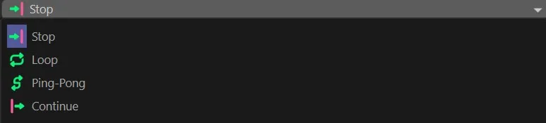
jdGeoFlow Loop Modes.
Cycles
Section titled “Cycles”Sets how many times the selected mode will run.
CamPoint tab
Section titled “CamPoint tab”The settings in this tab can be changed to alter the currently selected CamPoint.
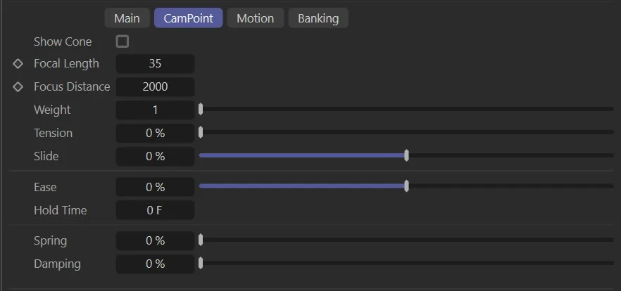
CamPoint tab settings.
Show Cone
Section titled “Show Cone”Enable to show the focus cone attached to this CamPoint.
Focal Length
Section titled “Focal Length”Sets the camera’s focal length when it reaches this CamPoint.
Focus Distance
Section titled “Focus Distance”Sets the camera’s focus distance when it reaches this CamPoint.
Weight
Section titled “Weight”Sets how much weight the selected CamPoint should have.
More weight will give that particular CamPoint more time on the track and other CamPoints will be re-timed to accommodate.
Tension
Section titled “Tension”Sets how sharply the camera’s path will bend around this point.
100% means the camera will take a very sharp corner at the given point.
A second way to adjust the Camera’s position on the track, within the CamPoint, without changing any weights.
Sets how the camera’s speed will change as it nears the CamPoint.
At 0 (zero), the camera will not change speed as it passes through.
At 100%, the camera will slow down as it reaches the CamPoint, then speed up again afterwards.
Hold Time
Section titled “Hold Time”Sets how long the camera should pause at the given CamPoint.
Spring
Section titled “Spring”Sets how much ‘springiness’ (a spring motion) the camera should have as it reaches this CamPoint.
Damping
Section titled “Damping”Increase this to reduce the number of oscillations after springing.
Motion tab
Section titled “Motion tab”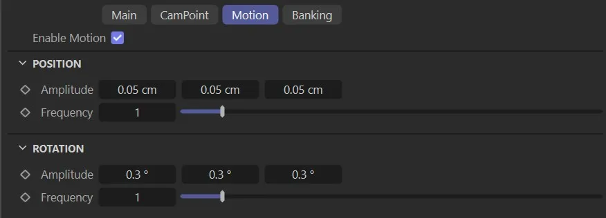
Motion tab settings.
Enable Motion
Section titled “Enable Motion”Enables a sine-based motion throughout the camera’s path.
Position
Section titled “Position”Amplitude
Section titled “Amplitude”The maximum distance at which the camera should oscillate around its ideal position.
Frequency
Section titled “Frequency”The frequency of the sine wave (Hz).
Rotation
Section titled “Rotation”Amplitude
Section titled “Amplitude”The maximum angles at which the camera should oscillate around its ideal rotation.
Frequency
Section titled “Frequency”The frequency of the sine wave (Hz).
Banking tab
Section titled “Banking tab”Auto Banking
Section titled “Auto Banking”Enable auto banking.
This will roll the camera left or right based on its horizontal rotation speed.
Min, Max
Section titled “Min, Max”The angle limits for the banking roll.
Sensitivity
Section titled “Sensitivity”Sets how much the camera’s horizontal rotation speed will affect the roll angle.
Easing
Section titled “Easing”Defines how much the angle changes as speed increases.
Path tab
Section titled “Path tab”Changing the Mode setting from Connect Points to Path, will open up a Path tab, which has the following parameter options.
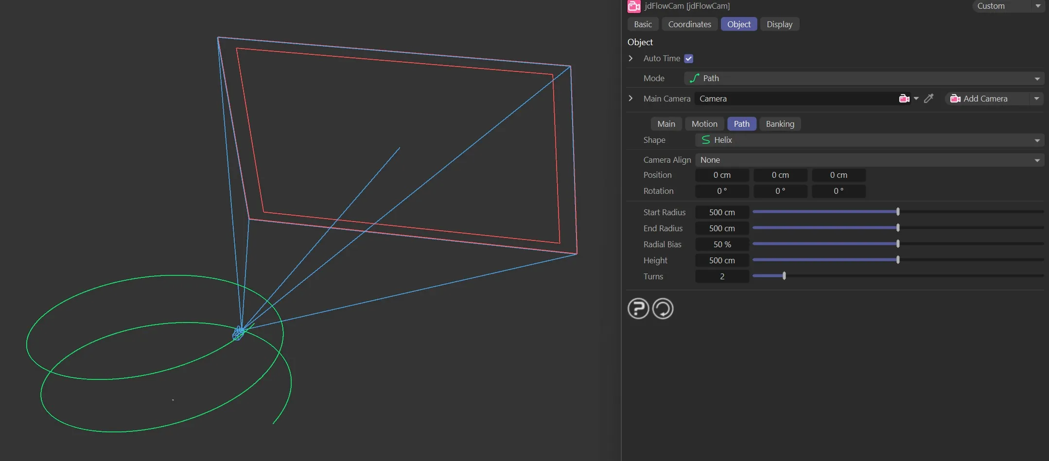
jdFlowCam, Path Mode menu settings.
Set as Circle, select a preset shape for the camera’s path.
The alternative options are: Arc, Line, Helix and Custom.
Each offers slightly different parameters, to fine tune the path.
With the Custom setting, any spline can be dropped into the Object field, which will open up under the Shape parameter.
The camera path will now be the custom spline selected.
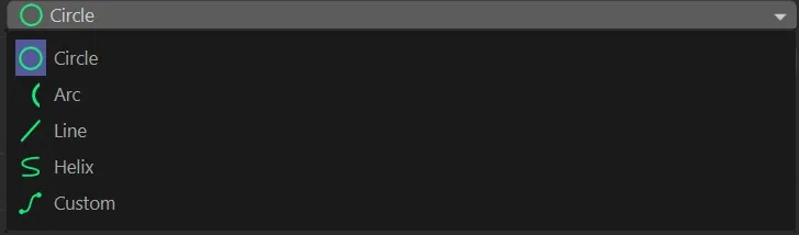
jdFlowCam, Path types.
Camera Align
Section titled “Camera Align”Set the camera axis that should follow the path spline.
The options are X, Y and Z but, as a default, none are selected and a user-defined orientation can be set with the Position and Rotation parameters.
Position
Section titled “Position”Sets the position of the path spline.
Rotation
Section titled “Rotation”Sets the rotation of the path spline.
Radius, Length, Start Radius, End Radius, Radial Bias, Height, Turns
Section titled “Radius, Length, Start Radius, End Radius, Radial Bias, Height, Turns”These are the options for defining the path spline.
These vary depending on the spline Shape type, matching the options provided when a Spline primitive of the same type is created.
Display tab
Section titled “Display tab”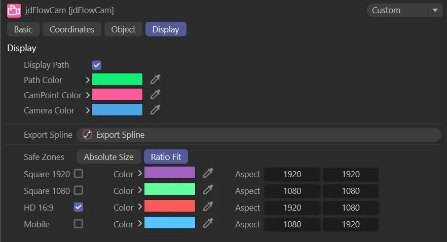
jdFlowCam, Display tab menu settings.
Display Path
Section titled “Display Path”When enabled, this displays the path of the camera.
Path Color
Section titled “Path Color”Sets the color of the pathway.
CamPoint Color
Section titled “CamPoint Color”Sets the color of the CamPoints.
Camera Color
Section titled “Camera Color”The camera color can be altered with this setting.
Export Spline
Section titled “Export Spline”Clicking this button allows you to export the spline used for the pathway, for future use.
Safe Zones
Section titled “Safe Zones”The Ratio Fit button is enabled, by default, but you can change this by clicking on the Absolute Size button.
You can select your safe zone setting by enabling one of the check boxes.
In addition, you can alter the colors for each option and change the Aspect, should this be necessary.
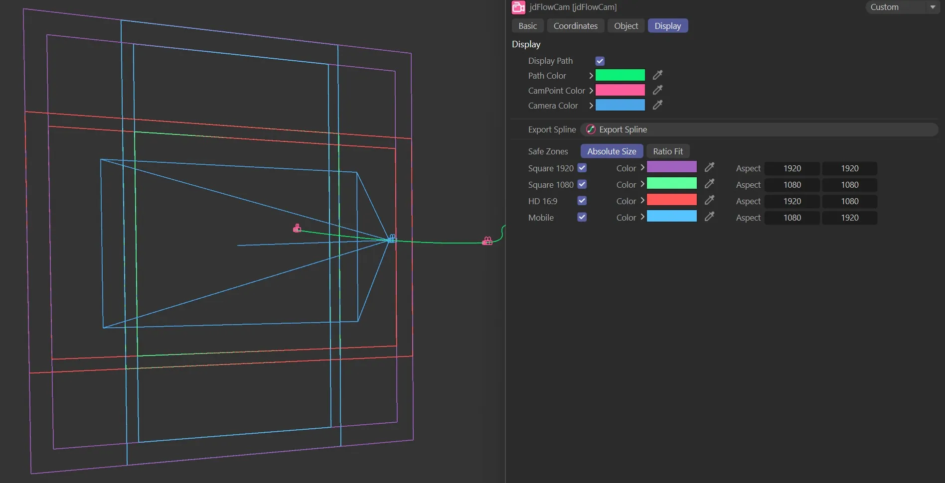
jdFlowCam, Safe Zones menu settings.
jdFlowCam Tag
Section titled “jdFlowCam Tag”This gives additional controls over the targeting system for your camera set-up.
Animation showing the target tag using 3 targets.
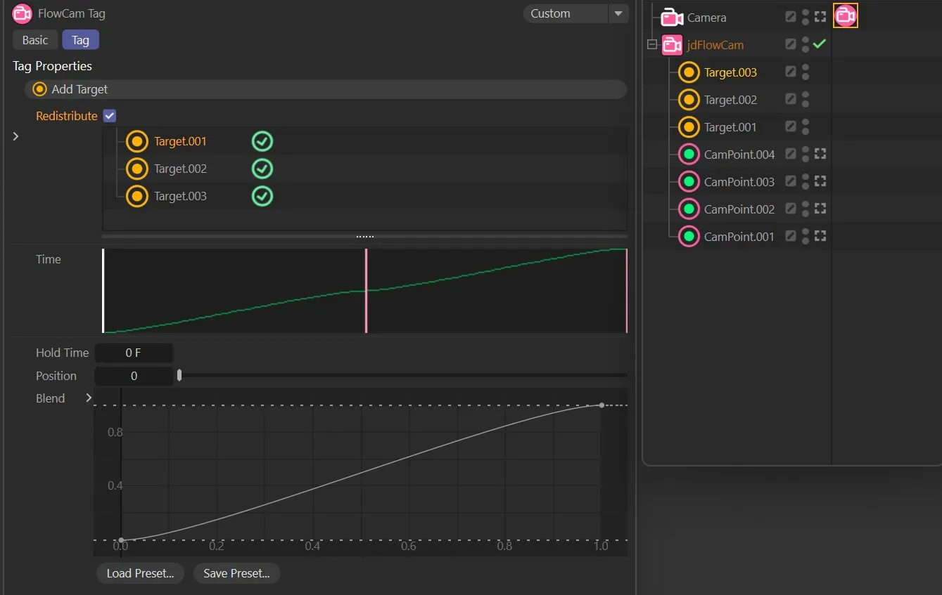
jdFlowCam Tag Properties.
Add Target
Section titled “Add Target”Here, a target can be added by simply clicking Add Target.
Alternatively, you can drop any object into this field to use as a target.
The visual display of the jdFlowCam target settings.
Hold Time
Section titled “Hold Time”The time that the cam will hold on the target.
Position
Section titled “Position”Alters the position of the target.
The easing Blend as the camera transitions between targets.
Copyright © 2026 INSYDIUM LTD. All rights reserved.