jdDriver
jdDriver is a tool that allows any attribute within Cinema 4D to be driven by essentially anything.
There are nine driver types in total: six signal drivers (Noise, Wave, Value, Time, Color, Switch) and three utility drivers (Sequencer, Folder, Merge).
Object Properties
Section titled “Object Properties”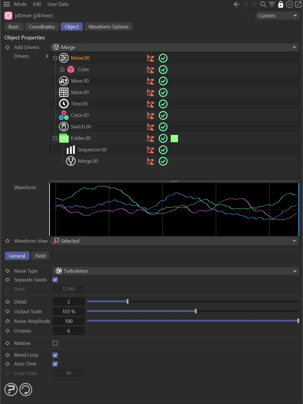
jdDriver settings Object tab menu.
How it works
Section titled “How it works”In order for jdDriver to start manipulating data, it needs a driver to base its modifications on.
This could be one of the preset drivers or any parameter within Cinema 4D that has been dragged and dropped into the tree.
In this case, if a parameter is added without being attached to a driver, this is known as a parameter driver.
A driver can drive one or many objects; these are always shown immediately nested into the driver and are driven objects.
The attributes of these objects that are to be driven by that driver are nested into the object, these are driven parameters.
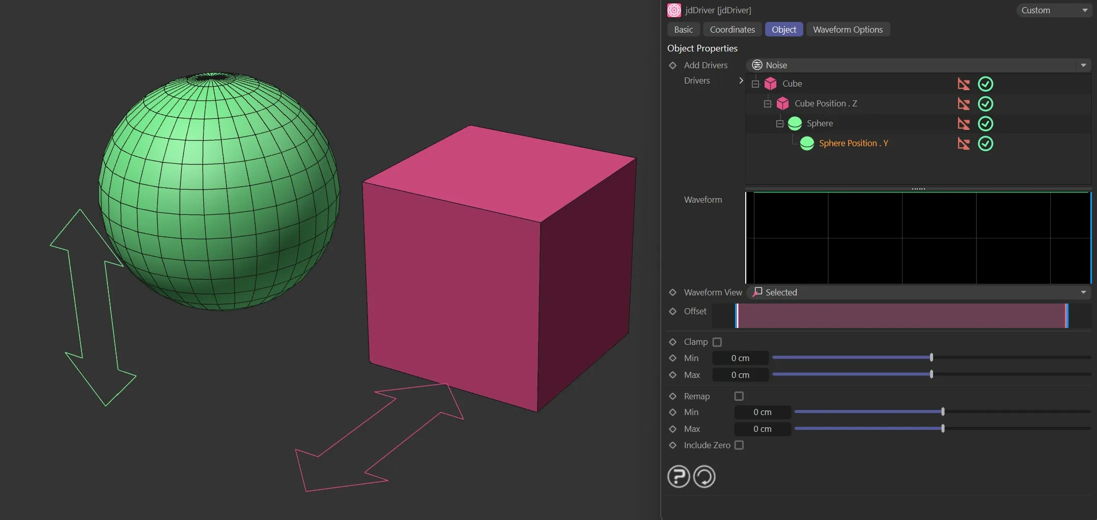
Sphere and Cube objects acting as drivers.
Each layer has a flag (green check mark red cross) to specify whether the layer is enabled or not.
Disabled layers have no effect on the scene.
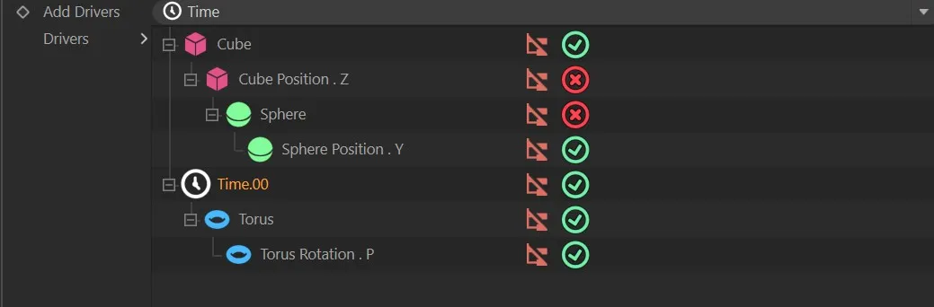
Illustration of flags operating on the individual layers within the Drivers field.
Add Drivers
Section titled “Add Drivers”This is a selection box for the user to insert one of the eight presets into the Drivers tree beneath.
The presets are: Noise, Wave, Value, Time, Color, Switch, Sequencer, Folder and Merge.
These drivers all modify parameters within Cinema 4D.
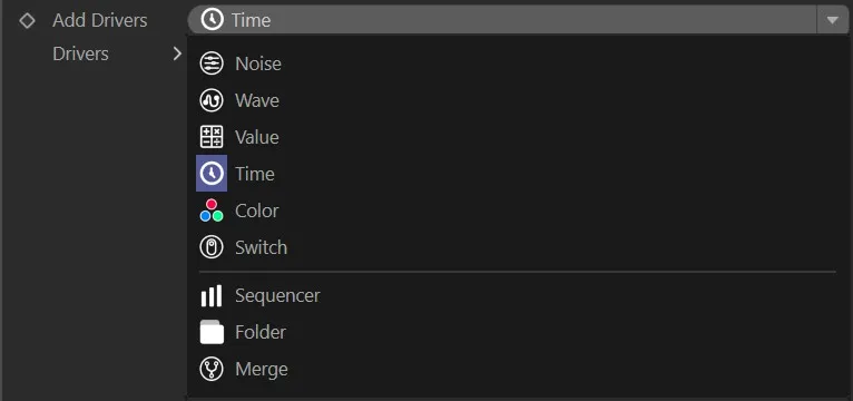
List of available driver types, in the Add Drivers drop-down menu.
Each driver has its own User Interface (UI) and parameter options.
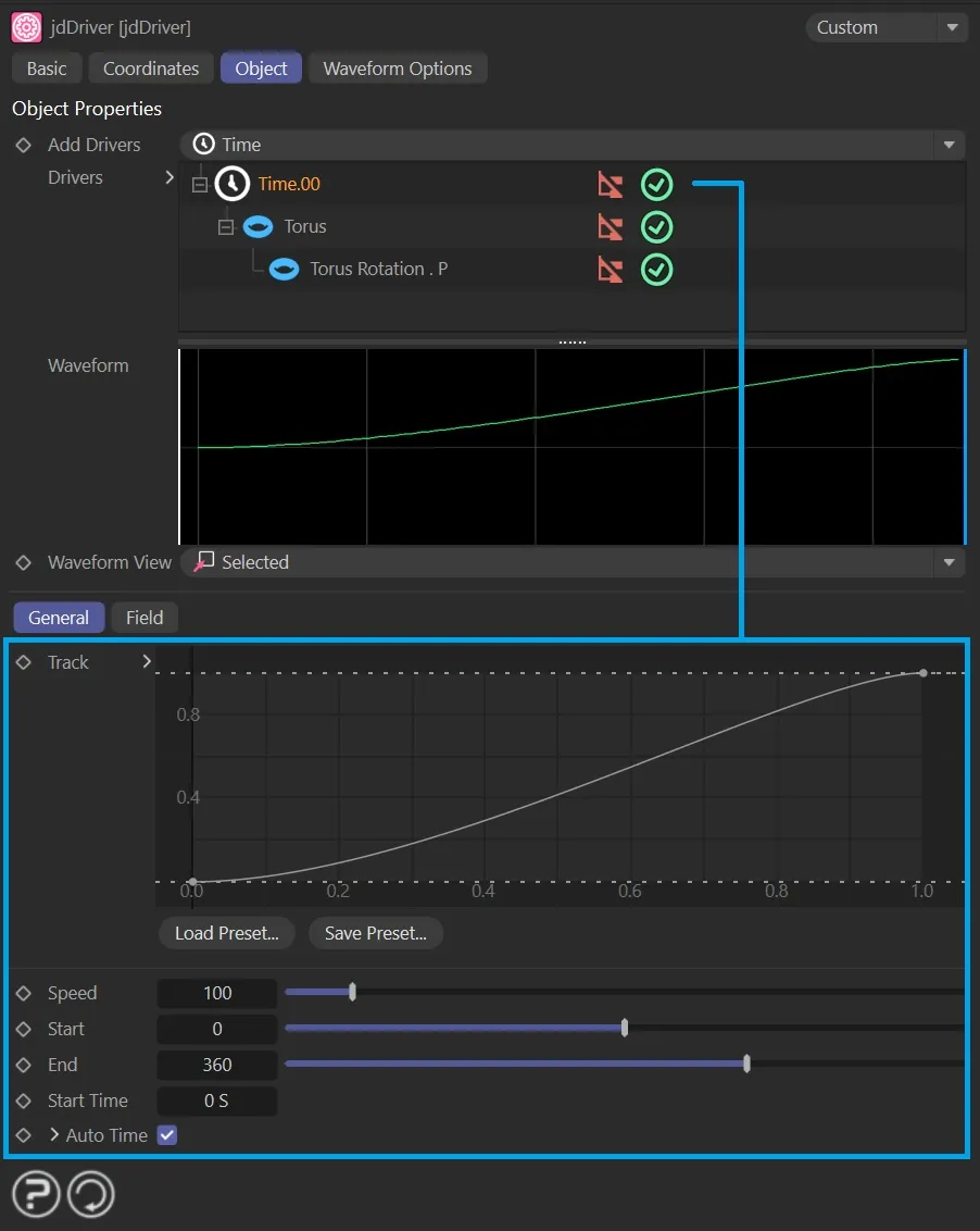
User Interface (UI) for the Time driver, showing its parameter options (more in the individual page, linked below).
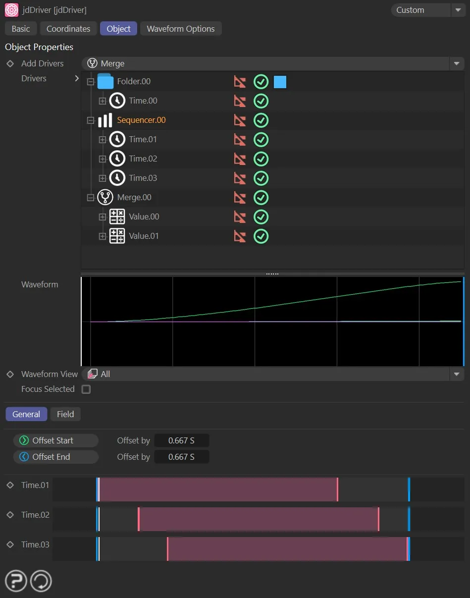
Parameter controls for the Sequencer driver (further information in the link, below).
Driver Types
Section titled “Driver Types”Add Parameter
Section titled “Add Parameter”When an object is selected, jdDriver allows the user to insert driven parameters through the Add Parameter selection box, these are extracted directly from the object that was inserted into the Drivers tree.
The available parameter options will depend on the object in the Drivers tree and will relate to position, rotation, scale, color, segments and size (amongst other options).
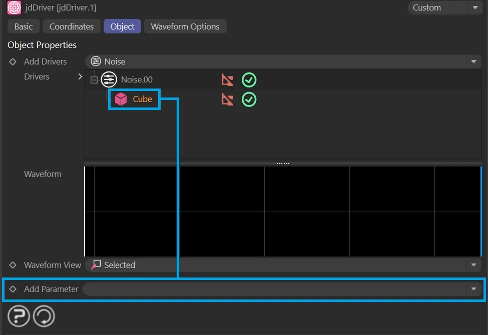
Add Parameter indicated with the Cube object in the Drivers tree.
Attributes can be dragged onto any driven object or driver to set it as a driven parameter.
For example, the Size.X ****attribute can be dragged under the Cube object, or directly onto the driver.
In the case that the parameter is added without the object being added, the object node is created to show this relationship.
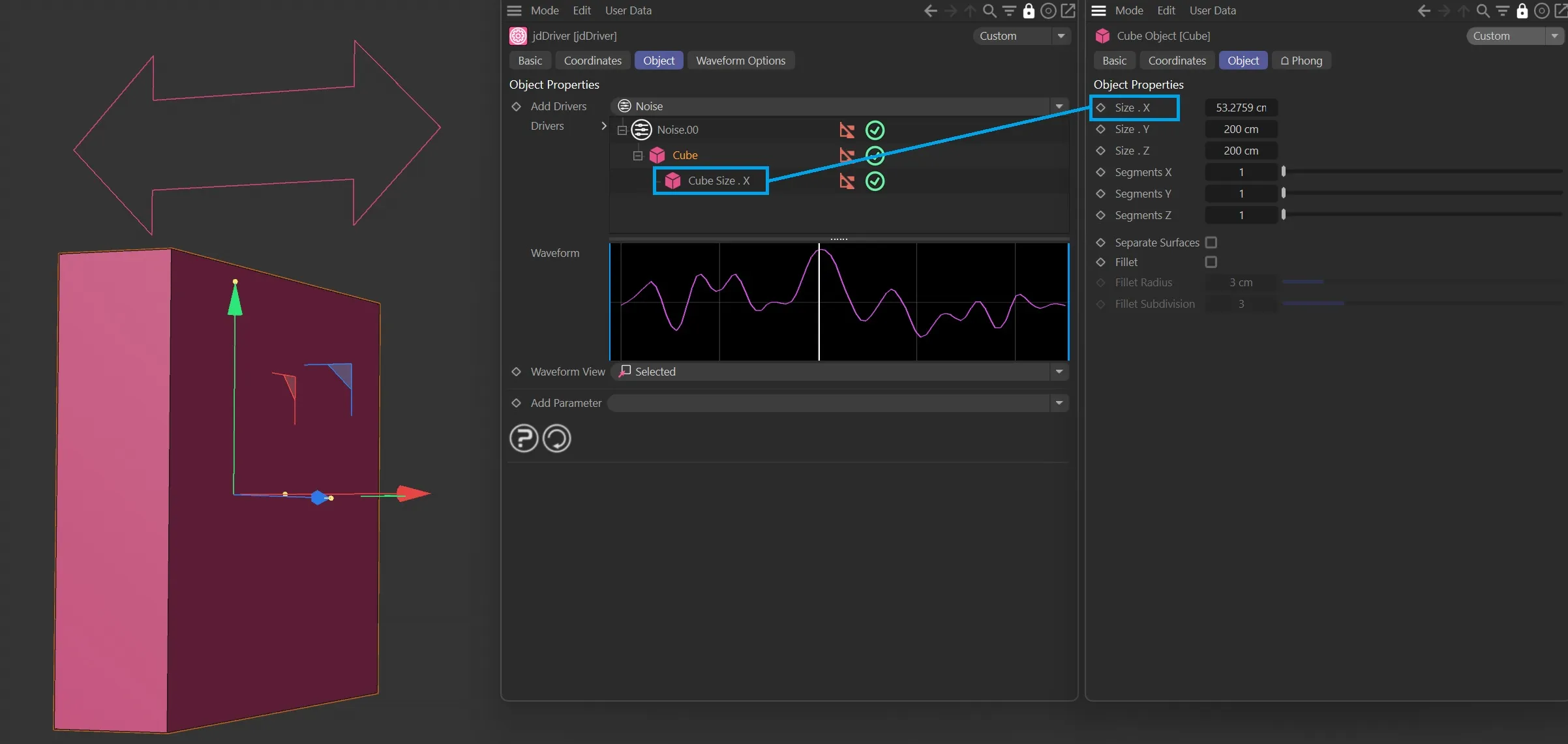
The Size.X parameter, as a child of the Cube in the Drivers tree.
Drivers
Section titled “Drivers”This tree is a visual representation of the driver – object parameter relationships.
When a driven object is selected in the Drivers tree, a number of options become available to the user.
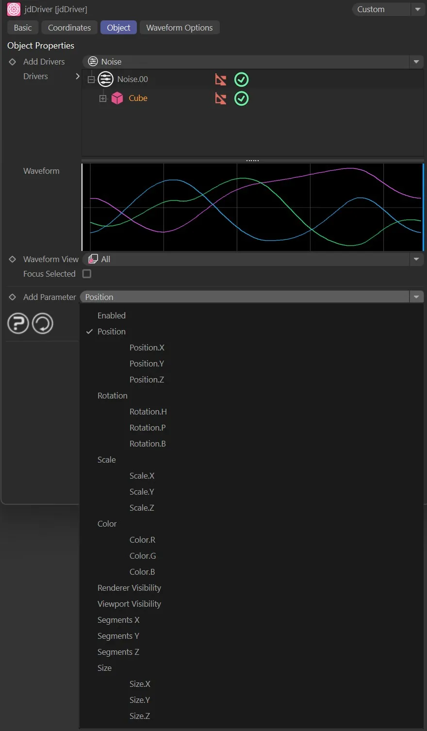
Parameter options available for the Cube object, in the Add Perimeter drop-down menu.
Waveform
Section titled “Waveform”This graph tracks and displays the values of the parameters that are being modified by jdDriver.
The Waveform graph.
Waveform View
Section titled “Waveform View”Set as Selected, by default, this dropdown option allows the user to change the data that is displayed on the Waveform graph.
The three settings for the Waveform feature are: Off, Selected and All.
Disables the Waveform feature.
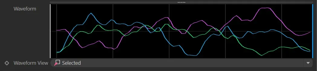
Selected
Section titled “Selected”Displays only the driven parameters that are currently selected and highlighted by the user.
Displays all the values that are driven by jdDriver.
When All is chosen, an additional Focus Selected parameter opens up.
Focus Selected
Section titled “Focus Selected”Checking this box allows the user to highlight individual parameters from the Drivers tree to display only them in the Waveform display.
Offset
Section titled “Offset”This is a graphical representation of the timeline, for the user to drag and move the area that will control when the modification will be active for the currently selected driven parameter.
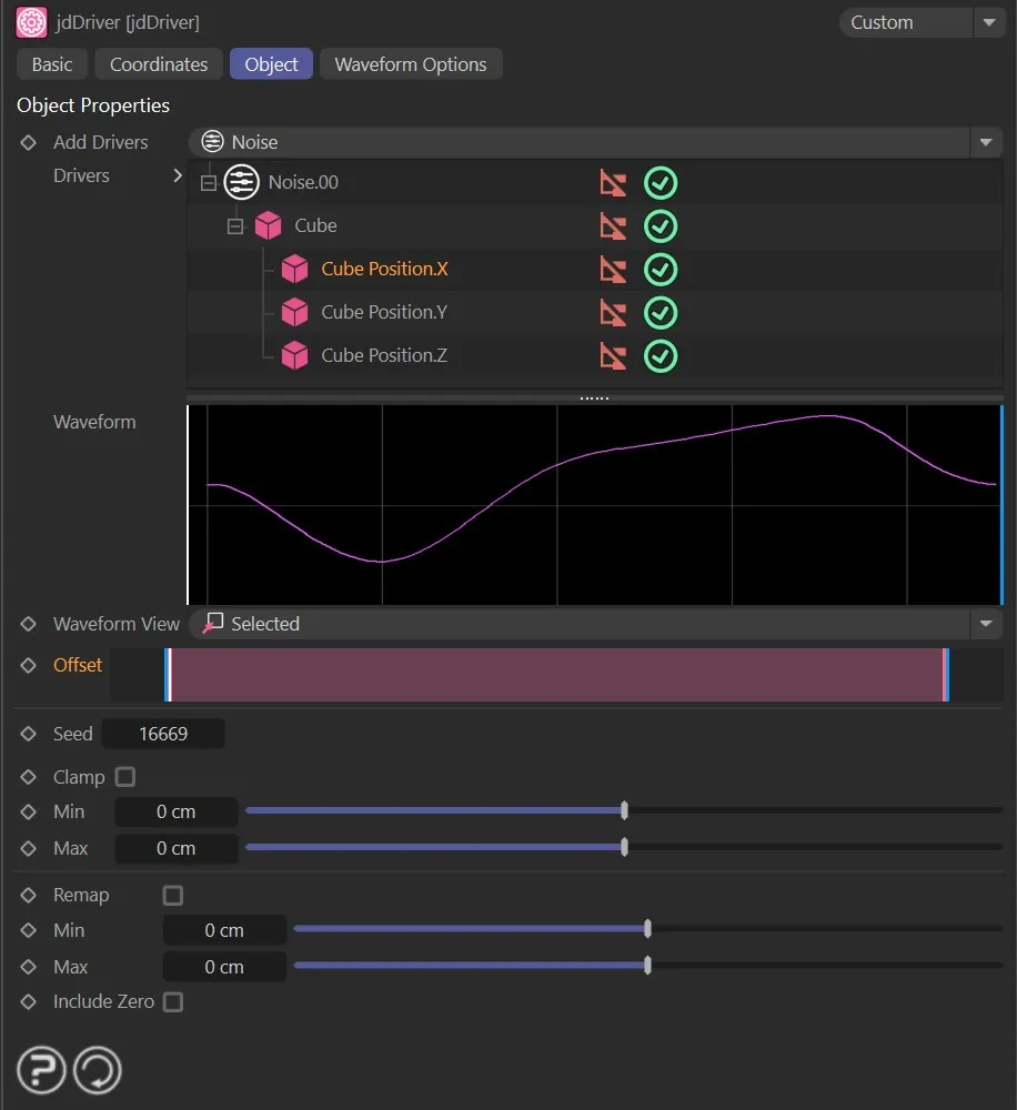
Image demonstrating the Offset timeline.
Gives a unique seed setting to the waveform.
Check this box to restrict the driven parameter between a minimum and maximum value.
Min, Max
Section titled “Min, Max”The minimum and maximum values of the driven parameter.
This records the range of movement (input range) for the given value, and scales it to fit within the given min/max bounds.
Min, Max
Section titled “Min, Max”The minimum and/or maximum values to use in the remap.
Include Zero
Section titled “Include Zero”Includes the value zero in the input range.
This affects how the output range is scaled.
Clone Parameters
Section titled “Clone Parameters”For objects assigned to a cloner or an array, these parameters have additional options.
To add a clone parameter through a MoGraph cloner or an array (Generator), the parameter is dragged directly from the object which will have its attribute changed.
In order for multiple objects in the same cloner or array to be compatible with jdDriver, all objects need to be nested under a null object.
Clone Mode
Section titled “Clone Mode”Set as Same, by default.
The alternatives are: Step and Random.
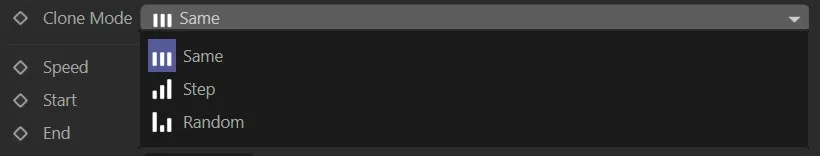
Clone Mode settings.
This mode ensures that all clones are following the same values; this doesn’t contain extra options.
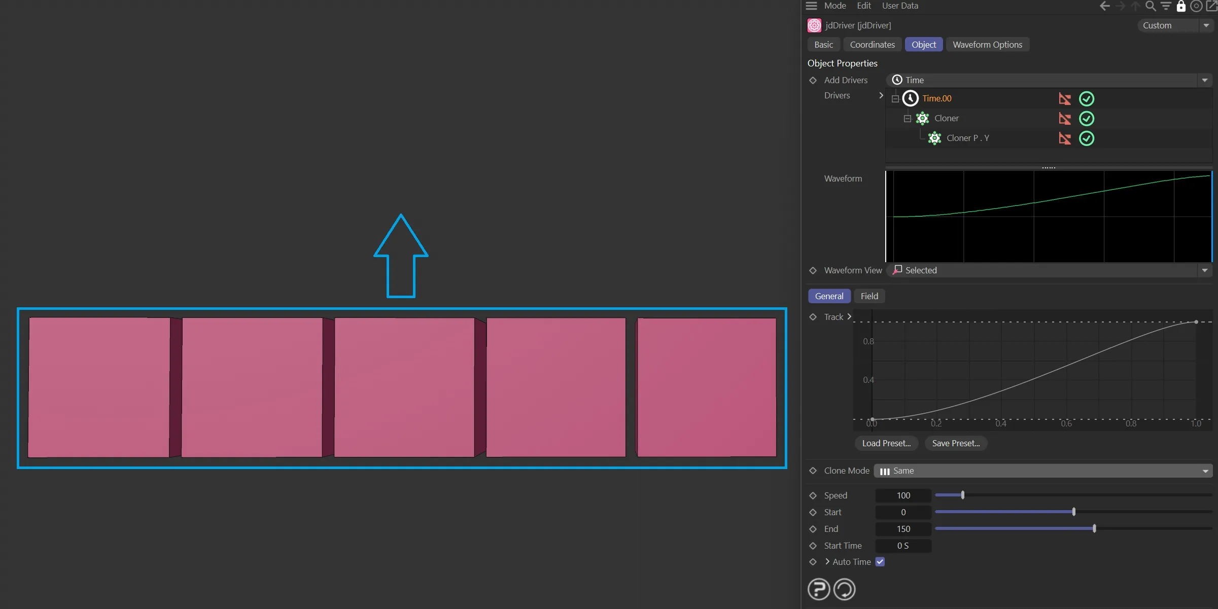
Clone Mode set to Same.
Each clone will start and end its animation in sequence.
There is an additional, Step parameter available.
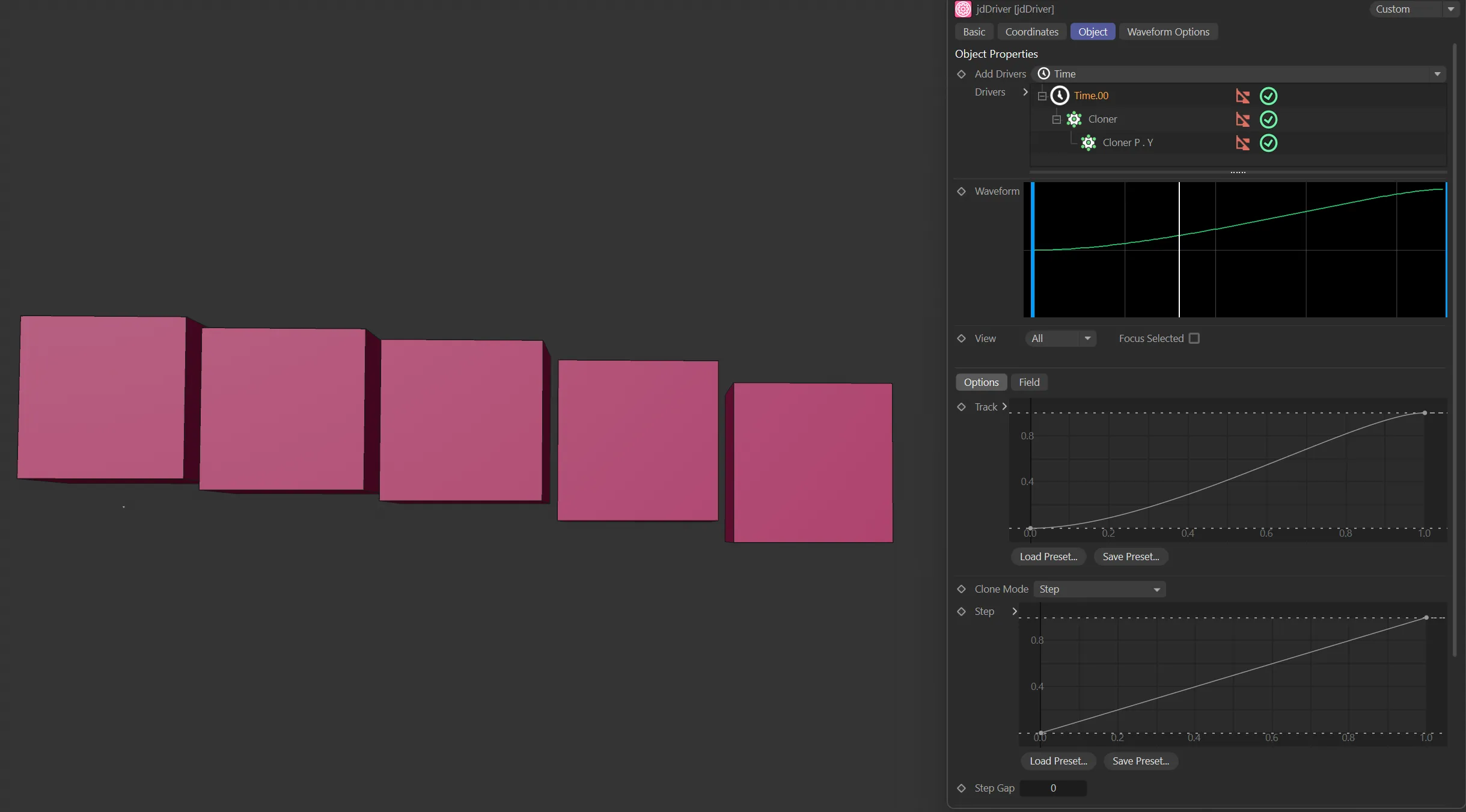
Clone Mode set to Step.
The step curve changes the degree of change between clones.
This editable spline changes the point at which stepped clones activate in the animation.
Step Gap
Section titled “Step Gap”Adds time space between the sequence.
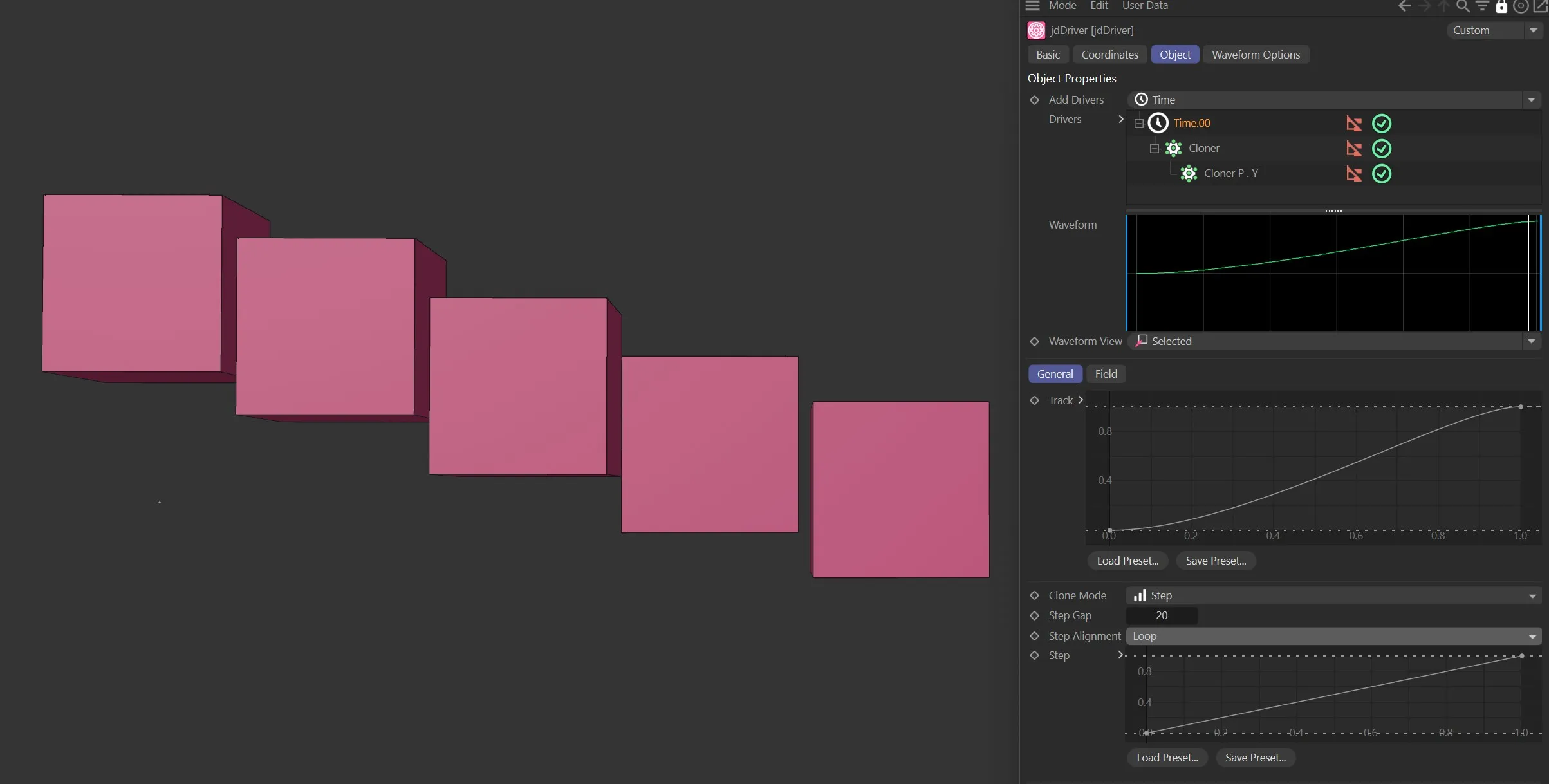
Here, the Step Gap is set to 10, with the Clone Mode as Step.
Random
Section titled “Random”The clones will be in a random pattern, further ‘controlled’ by the following two parameters.
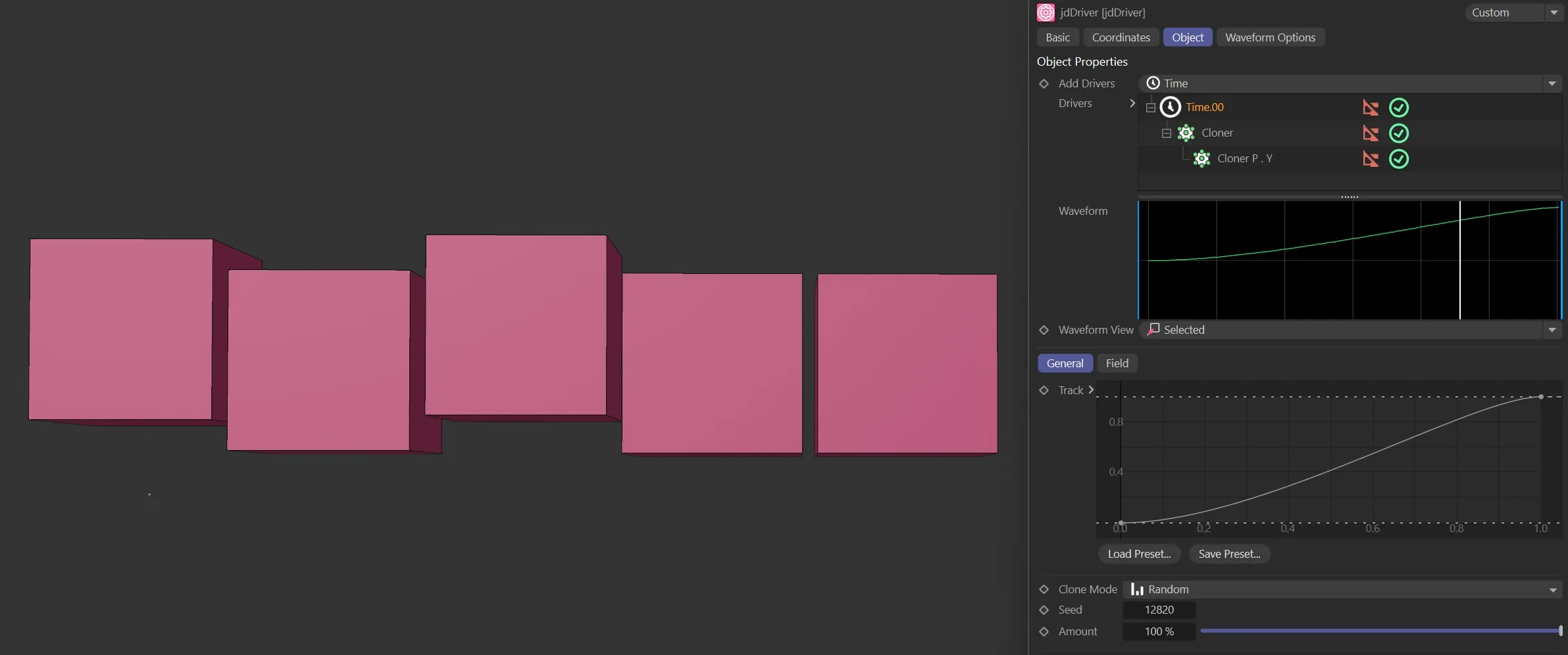
In this second image, with the Clone Mode as Random, the Cubes are in a random pattern.
The seed number to use to generate the random pattern.
Amount
Section titled “Amount”The percentage amount of randomness to apply.
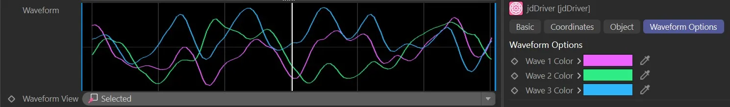
Waveform Options tab
Section titled “Waveform Options tab”This tab allows the user to customize the colors of the waves displayed within the waveform graph.
Wave n Color
Section titled “Wave n Color”Each wave color corresponds to a wave displayed in the waveform graph.
This color can be user-defined.
The Waveform graph.
Copyright © 2026 INSYDIUM LTD. All rights reserved.