

nxTrail
nxTrail draws trails along the path your NeXus particles travel, either as a fast viewport overlay or as renderable Blender curves.
Add it from Add ▸ INSYDIUM NeXus ▸ nxTrail. It arrives as an empty. It does not create trails on its own: you add one or more emitters to its Emitters list, and it records a trail for every particle those emitters produce. All of its settings live in Properties ▸ Physics.
nxTrail is a generator object, so it has a single Object Properties tab. It has no Groups Affected, Mapping or Falloff tabs.
A fountain of particles arcing under gravity, each leaving a trail behind it. The Display is set to Splines, so the trails are real curves in the scene.
Object Properties
Section titled “Object Properties”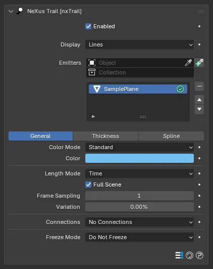
The nxTrail panel in Properties ▸ Physics. Each trail source in the Emitters list has its own General, Thickness and Spline sections.
Enabled
Section titled “Enabled”Turns nxTrail on or off. Disable it to stop trail generation without deleting the object.
Display
Section titled “Display”Sets how the trails are shown and is the main choice on this object. Set as Lines, by default. The alternative is Splines.
- Lines: a viewport-only line overlay drawn straight from the particle data on the GPU. It is fast and needs no extra objects, but it is a preview only. It does not render.
- Splines: nxTrail builds real Blender Curves objects as children of the nxTrail empty, one per trail source. These curves render, so use this mode when you want the trails in your final image, or to feed them into other objects such as a Curve to Mesh setup.
The Thickness and Spline sections below only shape the generated curves, so they take effect in Splines mode.
Emitters
Section titled “Emitters”The list of particle sources nxTrail draws trails for. Add an nxEmitter with the Object field or the add button, and nxTrail records a trail for each of that emitter’s particles. Add several emitters to trail more than one source at once.
Each source in the list has its own Enabled toggle and Name. Select a source to edit its settings, which are split across three tabs on the source: General, Thickness and Spline, shown below.
General
Section titled “General”The core trail settings for the selected source: color, how long the trail is, how points are connected and what happens when a trail is full.
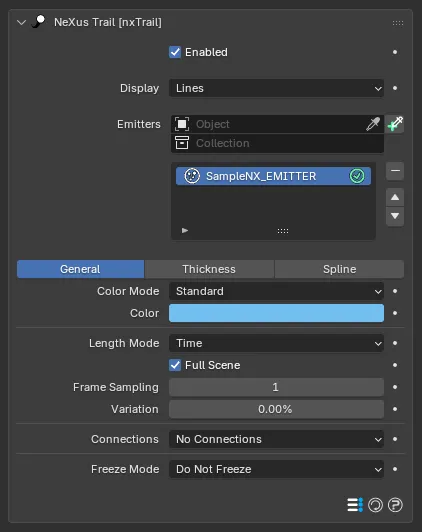
The General sub-tab on the selected trail source, at its defaults. The extra Connections and Freeze settings appear below as you change those options.
Color Mode
Section titled “Color Mode”Sets how the trail is colored. Set as Standard, by default. The alternative is Gradient.
- Standard: the trail uses a single Color.
- Gradient: a gradient is sampled along the length of the trail, so the color changes from the head to the tail.
The single trail color, used in Standard mode. Defaults to blue.
In Gradient mode a gradient control replaces this, defaulting to a blue-to-red ramp.
Length Mode
Section titled “Length Mode”Sets how the trail length is measured. Set as Time, by default. The alternative is Distance.
- Time: the trail covers a span of time (in frames or seconds).
- Distance: the trail covers a fixed length in scene units.
Full Scene
Section titled “Full Scene”Only shown in Time mode. When on, the trail grows for the whole scene duration. Enabled by default. Turn it off to set an explicit Length instead.
Length
Section titled “Length”The trail length. In Time mode this is shown only when Full Scene is off, and is measured in time (defaults to 30 frames). In Distance mode it is measured in scene units (defaults to 1m).
The Time value has a clickable f/s toggle to switch between frames and seconds, a NeXus-wide convention on time settings.
12 frames
64 frames
A short Length, on the left, gives brief streaks that follow just behind each particle. A long Length, on the right, trails almost the whole arc.
Frame Sampling
Section titled “Frame Sampling”Records a trail point every N frames. Defaults to 1, which stores a point on every frame. Raise it to store fewer points, which lightens the trail without shortening it. It changes the spacing of the points, not the length of the trail.
Variation
Section titled “Variation”Adds a random amount to each trail’s length, so the trails are not all the same size. Set as a percentage. Defaults to 0%.
Connections
Section titled “Connections”Sets how particles are linked into trail segments. Set as No Connections, by default, which gives each particle its own history trail. The other options build connected splines between particles in different ways.
- No Connections: each particle records its own trail as it moves. This is the basic particle trail.
- Straight Sequence: consecutive particles are linked in emission order to form a single trail.
- Segmented Sequence: like Straight Sequence but broken into short segments with gaps between them.
- Multiple Sequence: builds several splines from the particle source at once.
- All Points: links every pair of particles in the source into a dense net.
- Nearest Index: links consecutive particles in ascending particle-ID order.
- Nearest Distance: links particles that fall within a distance window.
- Cluster: groups particles by proximity and links within each cluster.
- Constraints: links particles along their nxConstraints bonds.
The extra settings below appear depending on the chosen option.
Segment Length
Section titled “Segment Length”Shown for Segmented Sequence. The length of each segment. Defaults to 1, the shortest possible segment, which links two adjacent particles.
Gap Length
Section titled “Gap Length”Shown for Segmented Sequence. The length of the gap between segments. Defaults to 1.
Shown for Multiple Sequence. Sets how particles are shared out between the splines. Set as Alternating, by default. The alternative is Sequential.
- Alternating: particles are taken for each spline in turn.
- Sequential: each spline uses a contiguous run of particles.
Sequences
Section titled “Sequences”Shown for Multiple Sequence in Alternating mode. The number of interleaved splines. Defaults to 1.
Length
Section titled “Length”Shown for Multiple Sequence in Sequential mode. The number of particles used per spline. Defaults to 1.
Max Connections
Section titled “Max Connections”Shown for Nearest Index. The maximum number of outgoing links per particle. Defaults to 1.
Skip Particles
Section titled “Skip Particles”Shown for Nearest Index. Skips a particle’s outgoing links at a regular interval, thinning out the connections. Defaults to 0.
Min Distance
Section titled “Min Distance”Shown for Nearest Distance. Particles closer together than this are not connected. Defaults to 0m.
Max Distance
Section titled “Max Distance”Shown for Nearest Distance. Particles farther apart than this are not connected. Defaults to 0.1m.
Max Number
Section titled “Max Number”Shown for Nearest Distance. The maximum number of connections per particle. Defaults to 0, which leaves it uncapped.
Cluster Distance
Section titled “Cluster Distance”Shown for Cluster. Particles within this distance of one another share a cluster. Defaults to 0.1m. Raising it gives larger clusters, but fewer of them.
Min Particles in Cluster
Section titled “Min Particles in Cluster”Shown for Cluster. The smallest number of particles that can form a cluster. Defaults to 2, the minimum.
Constraint Type
Section titled “Constraint Type”Shown for Constraints. Sets which constraint bonds are drawn. Set as All Types, by default. The other options are Birth, Distance, Custom and Viscosity.
Destination Groups
Section titled “Destination Groups”Shown for Nearest Index, Nearest Distance and Cluster. Sets which particle groups can be connection targets. Set as Use All Groups, by default. The other options are Only Same Group, Only Different Groups, Specific Group and All Except Specific Group.
Shown when Destination Groups is set to Specific Group or All Except Specific Group. Assign the nxGroup to connect to, or to exclude.
Freeze Mode
Section titled “Freeze Mode”Sets what happens when a trail reaches its length limit. Set as Do Not Freeze, by default. The other options are Freeze Particle and Freeze Trail.
- Do Not Freeze: the particle keeps moving and drags its trail along behind it.
- Freeze Particle: the particle stops when its trail is full.
- Freeze Trail: the trail stops recording but the particle keeps moving, so the two separate.
Freeze Movement
Section titled “Freeze Movement”Shown when Freeze Mode is not Do Not Freeze. Stops the particle’s movement when it freezes. Off by default.
Freeze Scale
Section titled “Freeze Scale”Shown when Freeze Mode is not Do Not Freeze. Stops the particle’s scale from changing when it freezes. Off by default.
Thickness
Section titled “Thickness”Generates thickness and color data along each trail. It shapes the radius of the generated curves in Splines mode.
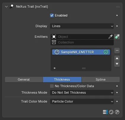
The Thickness sub-tab on the selected trail source. The Thickness controls below change with the chosen Thickness Mode.
No Thickness/Color Data
Section titled “No Thickness/Color Data”Leaves thickness and color data off the trail. Off by default. Turn it on to keep the trail as bare points, which disables the settings below.
Thickness Mode
Section titled “Thickness Mode”Sets how the trail thickness is produced. Set as Do Not Set Thickness, by default.
- Do Not Set Thickness: no thickness data is created.
- Set From Value: a uniform thickness along the trail, from the Thickness value.
- Use Spline: the thickness follows a spline sampled along the trail, so it can taper from head to tail.
- Use Radius (Current): the trail uses the particle’s current radius, the same value along its whole length.
- Use Radius (Variable): the particle radius is recorded at each point, so the trail thickness varies with the radius the particle had at that moment.
Thickness
Section titled “Thickness”Shown in Set From Value mode. The uniform trail thickness. Defaults to 0.01m.
Thickness Variation
Section titled “Thickness Variation”Shown in Set From Value mode. Adds a random amount to the thickness, so trails are not all the same width. Defaults to 0.
Thickness Spline
Section titled “Thickness Spline”Shown in Use Spline mode. The curve control that sets thickness along the trail. The left of the curve is the head of the trail and the right is the tail. Tapers to zero by default.
Spline Max
Section titled “Spline Max”Shown in Use Spline mode. The maximum thickness the spline maps to. Defaults to 0.01m.
Spline Time
Section titled “Spline Time”Shown in Use Spline mode. The time over which the thickness spline is sampled. Defaults to 30 frames, with the f/s toggle.
Trail Color Mode
Section titled “Trail Color Mode”Sets where the per-point color comes from. Set as Particle Color, by default. The alternative is Per-Vertex Color.
- Particle Color: the whole trail takes the particle’s current color, so changing the particle color recolors the entire trail.
- Per-Vertex Color: a color is stored for each point as it is recorded, so the trail can hold a run of different colors along its length.
Spline
Section titled “Spline”Controls the shape of the curves nxTrail builds in Splines mode.
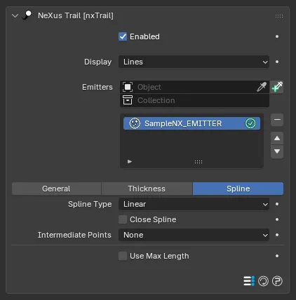
The Spline sub-tab on the selected trail source. Number, Angle and Max Length appear as you set Intermediate Points or turn on Use Max Length.
Spline Type
Section titled “Spline Type”The kind of curve generated. Set as Linear, by default. The other options are Bezier and B-Spline.
- Linear: an exact polyline through the trail points.
- Bezier: a smoothed Bezier curve.
- B-Spline: a smooth B-Spline.
Close Spline
Section titled “Close Spline”Joins the ends of each generated spline into a loop. Off by default.
Intermediate Points
Section titled “Intermediate Points”Inserts extra points between the trail points to smooth or refine the curve. Set as None, by default.
- None: the resolved trail points are used directly.
- Uniform: an even number of extra points is added along each segment, set by Number.
- Adaptive: extra points are added only near corners sharper than the Angle threshold.
Number
Section titled “Number”Shown in Uniform mode. The number of intermediate points added per segment. Defaults to 0.
Shown in Adaptive mode. The angle threshold above which a corner gets extra points. Defaults to 15°.
Use Max Length
Section titled “Use Max Length”Limits the length of each generated spline. Off by default.
Max Length
Section titled “Max Length”Shown when Use Max Length is on. The maximum spline length in scene units. Defaults to 1m.
Copyright © 2026 INSYDIUM LTD. All Rights Reserved.